INSPIRE (Interplanetary NanoSpacecraft Pathfinder In a Relevant Environment)
Non-EO
NASA-JPL
Quick facts
Overview
| Mission type | Non-EO |
| Agency | NASA-JPL |
INSPIRE (Interplanetary NanoSpacecraft Pathfinder In a Relevant Environment)
Overview Spacecraft Launch Sensor Complement Ground Segment References
INSPIRE is a NASA/JPL interplanetary demonstration mission of two nanosatellites despatched beyond Earth orbit to evaluate functionality, communications, navigation, and payload-hosting technologies. According to NASA, this mission's fundamental goal "is to open deep-space heliophysics and planetary science to the CubeSat community." 1) 2)
The INSPIRE project is a NASA/JPL partnership mission with the University of Michigan, Ann Arbor, MI; Cal Poly, San Luis Obispo, CA; UCLA (University of California Los Angeles), and the University of Texas, Austin, TX, in partnership with GAVRT (Goldstone-Apple Valley Radio Telescope).
Note: GAVRT is a partnership between NASA/JPL and the Lewis Center for Educational Research. The program is an authentic science investigation program for students in grades K through 12. Students learn how to be a part of a science team while they are making a real contribution to scientific knowledge. 3)
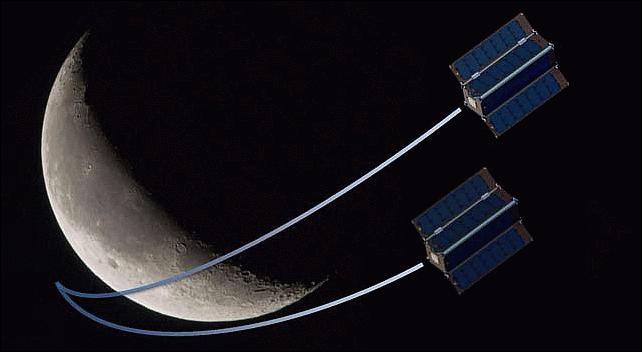
The mission objectives are: 4) 5) 6) 7)
• Demonstrate and characterize key nanosatellite telecommunications, navigation, command & data handling, and relay communications for a mother-daughter configuration
• Demonstrate science utility with compact science payload (1/2U Helium Magnetometer and combination Star-Tracker/Imager)
• Demonstrate the ability to monitor and power cycle COTS/university processing systems.
The INSPIRE project will accomplish a tiered set of technology-demonstration and education objectives: it will demonstrate that NASA CubeSats can:
1) operate, communicate, and be navigated far from Earth
2) host and support CubeSat components whose hardware has not yet had the opportunity to fly in deep space
3) deliver useful science that in turn opens future mission opportunities for investigators.
These objectives intimately embody many NASA strategic objectives, and enable a new generation of low-cost solar system explorer. INSPIRE's demonstration of CubeSat functionality and utility in the deep-space environment is crucial as a stepping-stone for interplanetary CubeSats. By leveraging JPL's 50 plus years of deep space experience, INSPIRE will establish a flight heritage for future interplanetary CubeSat missions, as well as creating a cadre of partner universities experienced with the challenges of interplanetary missions.
The two identical spacecraft will be launched simultaneously as secondary payloads and deployed to Earth-escape. The nominal mission will last for three months and achieve an expected Earth-probe distance of 1.5 x 10⁸ km (dependent upon escape velocity as neither spacecraft will have propulsion capability). Two spacecraft provide redundancy to reduce the risk in meeting the project goals (with the exception of crosslink communications, which will be demonstrated early in the mission timeline).
Once proven, interplanetary CubeSats can provide multiple adjunct roles in support of deep-space human missions, e.g., external inspection of flight systems, "third viewpoint" observation of operations, advance reconnoitering of exploration sites, and continuous monitoring observations after humans depart a site. CubeSats are widely recognized as a disruptive technology. Yet programmatic missions on which their deep space development could piggyback are increasingly rare; and competitively selected PI-led missions are unlikely to incorporate CubeSat-platform based operations concepts until such platforms are demonstrated, yielding quantified heritage performance.
Mission concept: JPL-built spacecraft; collaborative partnerships with Michigan, Texas, UCLA and CalPoly/Tyvak for COTS systems. Ground stations at DSN and secondary stations compatibility.

INSPIRE overview: INSPIRE, which is a deep-space-flight-ready in the summer of 2014, will become the world's first dedicated interplanetary CubeSat mission, opening deep-space heliophysics and planetary science to the CubeSat revolution. The INSPIRE mission will accomplish a tiered set of technology-demonstration and education objectives: it will demonstrate that NASA CubeSats can (1) operate, communicate, and be navigated outside of Earth's orbit; (2) host and support CubeSat components whose hardware has not yet had the opportunity to fly in deep space; and (3) deliver useful science that in turn opens future mission opportunities for investigators. These objectives intimately embody many NASA strategic objectives, and enable a new generation of low-cost solar system explorers.
Spacecraft
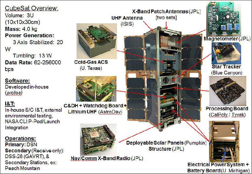
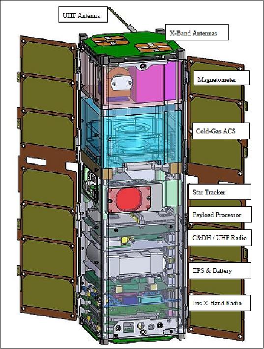
The INSPIRE flight system comprises two identical, three-axis-stabilized 3U spacecraft that combine existing subsystems for C&DH watchdog, attitude determination, and power functions with next-step modifications of subsystems for cold-gas attitude control and deep-space navigation & communication. Demonstrating the integrated system performance of these core spacecraft components will establish a proven foundation for diverse future NASA missions to host special-purpose payloads in deep space.
The nanosatellite structure uses a Pumpkin kit. The spacecraft has a size of 10 cm x 10 cm x 30 cm, a mass of ~4.0 kg, power generation of 20 W, and data rates between 62 bit/s and 256 kbit/s depending on range.
JPL is designing and integrating the spacecraft while the university partners are providing many of the subsystems: UTA(University of Texas, Austin) provided the attitude control system, U. Michigan / AstroDev has provided the electrical power system and C&DH, as well as serving as a ground station, CalPoly has provided a processing board, and GAVRT is providing receive-only operations at DSS-13.
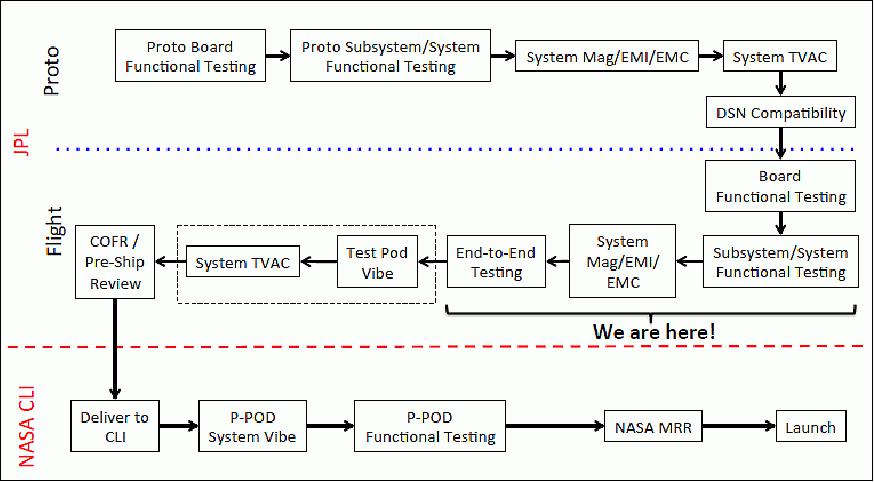
Each of the university subsystems is being built with JPL oversight and consulting, thus providing the CubeSat community several experienced deep space developers for future interplanetary missions. These subsystems will be integrated at JPL in collaboration with the students who developed them through internship programs. Each spacecraft will be subject to extended bench-top operations to verify functionality. The spacecraft will then be tested as a unit prior to launch delivery, undergoing thermal/vac, vibration and shock testing.
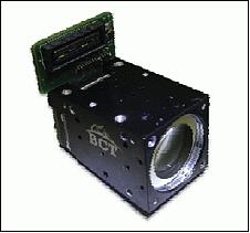
ADCS (Attitude Determination and Control Subsystem): A commercial star tracker / imager, NSC-1 (Nano Star Camera-1) of BCT (Blue Canyon Technologies), Boulder, CO, will provide a majority of the attitude control information (2 NSC-1 devices are flown), including quaternions and rates, but chip-scale gyros and photodiodes will provide verification. Low-fidelity attitude estimation algorithms will verify sun-direction (the most critical angle to acquire) to assure correct panel orientation and keep-out angles for the exposed devices.
Parameter | Value | Parameter | Value |
Attitude solution update rate | 5 Hz | Cross-axis accuracy | 7 arcsec (1σ) |
Accuracy about roll axis | 24 arcsec (1σ) | Time-to first fix | 2 seconds |
FOV (Field of View) | 11.6º x 9º | Mass | ≤0.5 kg including baffle |
Volume | ≤5 cm x 5 cm x 10 cm including baffle | Nominal power consumption | ≤0.5 W |
Operating voltage | 5 ±0.1 VDC | Data Interface (optional control electronics) | RS-422, I2C or SPI |
Attitude control will be provided by a four-thruster cold-gas system provided by UTA (University of Texas, Austin). Building from MEPSI (MEMS-based PicoSat Inspector) heritage from STS-116 (Dec. 10-22, 2006), the tank is 3D-printed, and contains thrusters that can be fired together or independently depending on direction and impulse required. The C&DH subsystem will run a limited attitude control algorithm for both detumbling and nominal flight operations, that will take into account relevant sensors and spin rates – for instance, during initial detumble, only the photodiodes and gyros will be used to mitigate expected motion blur of the star tracker during the initial fast rotations. The 3D-printed tank provides design flexibility and growth of system components until late in the design process.
C&DH (Command & Data Handling) subsystem: The core of the INSPIRE spacecraft consists of two parts: the watchdog board and the Iris deep space transceiver/transponder. The watchdog board is based on the proven MSP430 microprocessor (Pumpkin Inc.) flown on many successful CubeSat missions, including RAX-2 (Radio Aurora Explorer) of the University of Michigan (launch Oct. 28, 2011) and Delfi-C3 (Triple-unit CubeSat Configuration of TU Delft, launch April 28, 2008), and has also demonstrated limited radiation tolerance in experimental testing . The board will be responsible for basic command and data-handling; interfacing with the radio, attitude control system, star tracker, electrical power system, and payloads via UART, I2C and SPI lines; and monitoring spacecraft health. It also provides a cascading watchdog architecture responsible for monitoring and resetting all subsystems, if necessary, in the event of SEUs or other fault conditions. The C&DH subsystem contains two-SD cards (one serves as a cold-spare), a real-time-clock, onboard UHF radio, MEMs gyro, watchdog circuitry, and even a hardwired identification circuit to uniquely identify the spacecraft. Heritage from the C&DH subsystems is derived directly from RAX and RAX-2 spacecraft, where this functionality was separated into three boards. AstroDev Inc. has developed a new generation system, with the same circuitry, that fits within a single board.
EPS (Electrical Power Subsystem): The EPS is built from RAX/RAX-2 heritage, which has now cumulatively demonstrated over two years of successful operations in Earth-orbit. Fixed solar panels cover three sides of the INSPIRE spacecraft, and together with two deployable panels, provide greater than 20 W of onboard power when oriented toward the sun.
RF communications: Primary communication with the spacecraft will be over the DSN compatible Iris X-band transceiver/transponder. The radio relies on dual receiver / transmitter antennas located on either end of the spacecraft, providing nearly omnidirectional communication coverage. With a 5 W transmitter, the link budget shows that the radio can communicate at greater than 1 kbit/s at a distance of 1.5 million km, but the performance is flexible for data rates between 62.5 bit/s up to 256 kbit/s (depending on range). The radio provides coherent uplink and downlink, allowing for accurate ranging and Doppler measurements to be made on the ground. Away from a gravitational body, the expected navigational accuracy is less than 500 km relatively close to Earth, and between 1000 and 2000 km further along the mission timeline.
The CCSDS compliant radios have a limited amount of onboard memory to buffer received and transmitted data, and also allow for a so-called "firecode" providing the ability to externally reset the spacecraft if needed. The radios themselves are quite robust, and build upon lessons learned from the from the M-Cubed/COVE processing experiment for digital board design. The Iris radio itself builds from the Electra radios at Mars and the LMRST (Low-Mass Radio Science Transponder) system slated to fly on the LMRST-Sat CubeSat project.
In addition to the X-band radio, an AstroDev Lithium UHF radio is built onto the C&DH board to provide a crosslink capability between the spacecraft. This allows for direct-relay and store-and-forward-relay communications between the ground and either spacecraft. The UHF radios also allow for a firecode command to provide additional reset capability.
Iris transponder: The JPL developed Iris deep space transceiver/transponder has a size of 0.4U and a mass of 0.4 kg, consumes 12.8 W, and interoperates with NASA's DSN (Deep Space Network) on X-band frequencies (7.2 GHz uplink, 8.4 GHz downlink) for command, telemetry, and navigation. Iris features a significant subset of standard deep space transponder features, largely inherited from UST (Universal Space Transponder) and the Electra Proximity Operations UHF transceiver in the form of complex digital signal processing code hosted in FPGA. 9)
Iris also shares the basic hardware architecture with these larger transponders but in a more compact form. The main limitation of Iris compared to its larger siblings is not data formats and measurement precision, which are similar, but the smaller amount of power consumed from the spacecraft bus and radiated on the downlink. The lower power sets an upper limit on the data rate that can be used for a given range.
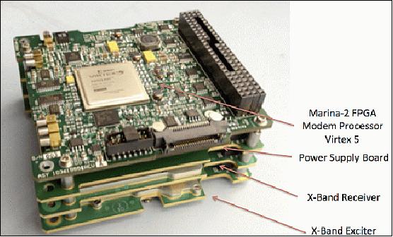
Architecture: The current Iris, Version 1, is a stacked set of four CubeSat-size boards interconnected with a Pumpkin standard PC-104 connector and antennas. The spacecraft interface is SPI (Serial Peripheral Interface), also interconnected via the PC-104. Per INSPIRE project policy, Iris V1 is assembled entirely from COTS parts, but the parts and architecture used have radiation hardened equivalents so that a more environmentally robust (and more expensive) model can be produced for a future customer. The INSPIRE approach to radiation events is to conduct a short mission and to tolerate radiation induced upsets through power-cycle resets as needed.
On top of the Iris stack is the Marina-2 FPGA (Field Programmable Gate Array) board featuring a commercial grade Virtex 5, bus power conversion for digital electronics, and associated circuitry. Digital signal processing and data handling are performed here.
The PSB (Power Supply Board) converts spacecraft bus voltage (nominal 7.4-8.3 VDC for a CubeSat such as INSPIRE) to the voltages required by the receiver and exciter boards. These are separate from the digital power rails on the Marina-2 board for noise control reasons. When powering Iris up, the Marina-2 board is powered first and the others are activated under its control. All power converters are designed to limit inrush to a CubeSat bus acceptable level of 3 A peak.
The receiver board performs a single conversion of X-band radio frequency (RF) at 7.2 GHz to a 112.5 MHz intermediate frequency (IF). The LO (Local Oscillator) for this down-conversion is provided by a PLL (Phase Locked Loop ) whose frequency is set under FPGA control. The IF is sub-harmonic sampled in quadrature and digitized at 12.5 Msample/s. These samples are then passed to the FPGA for baseband processing. The receiver has a demonstrated carrier acquisition sensitivity of better than -130 dBm and an RF passband suitable for use in any channel of the near Earth or deep space X-band uplink allocations, that is, 7.14 – 7.24 GHz. The front-end noise figure is approximately 5 dB and the IF bandwidth is 15 MHz. Covers are used on the receiver board to provide RF isolation from other nearby electronics and to provide a thermal heat removal path.
The exciter (or "transmitter") board generates a carrier frequency using a PLL under FPGA control that is about 2 MHz away from the intended transmission channel. This carrier is then quadrature modulated with baseband samples produced in the signal processing firmware of the FPGA to produce carrier, subcarrier, modulation as required for the mode selected, and shifting to the assigned carrier channel. A balanced vector modulator is used to suppress the original carrier frequency and images, 2 MHz and 4 MHz away from the intended signals respectively, to acceptable levels.
The exciter board also hosts the 50 MHz TCXO (Temperature Compensated Crystal Oscillator) that provides the reference frequency for all onboard operations: transmit and receive PLLs, DAC (Digital to Analog) and ADC (Analog to Digital) conversion, and FPGA clocking. All digital processing operations are therefore coherent to this oscillator.
The INSPIRE Iris uses a LGA (Low Gain Antenna) printed on CubeSat sized circuit boards. Each antenna board features two independent patch antennas, one for transmit at 8.4 GHz and the other for receive at 7.2 GHz. They each have a 3 dB bandwidth of about 300 MHz and are RHCP (Right Hand Circularly Polarized). Each has a peak gain of approximately 5 dB and a beamwidth of 80º.
Iris on INSPIRE does not use a diplexer for simultaneous transmit and receive. The printed antennas have over 35 dB of isolation from each other and bandpass filtering in their respective circuits produces sufficient total isolation for simultaneous transmission and reception at the stated power output and sensitivity levels.
An antenna board is mounted on each end of the INSPIRE spacecraft so that two roughly hemispherical views of the sky are supported, enabling communications from any spacecraft orientation. The favored direction is broadside to the board, that is, off one end or the other of the spacecraft, for maximum gain and circularity. A PA (power Amplifier) is provided on the exciter board for each transmit antenna and a LNA(Low Noise Amplifier) is provided on the receive board for each receive antenna. Antennas are selected by providing DC power to the corresponding amplifier under FPGA control. This approach eliminates the need for troublesome RF switches or relays (either for antenna selection or transmit/receive) and provides some operational redundancy.
Doppler navigation data: The uplink carrier frequency is precisely referenced to a maser clock at the DSN station. The downlink carrier from the spacecraft is then precisely phase referenced to the same maser to produce the Doppler data type. This is a measure of how fast the DSN station and spacecraft are moving with respect to each other and can be measured with a precision equivalent to a fraction of a mm/s. In processing this data, navigators compare the measured carrier phase to the "predicted" or "model" carrier phase and use this information to correct the assumed state vector of the spacecraft. Doppler data is most useful when there is a measurable change in the value such as is experienced when a spacecraft is in orbit about or passing near Earth, moon, or a planet. The Doppler signature from INSPIRE as it drifts slowly away from Earth is expected to be comparatively benign.
Ranging navigation data: During a tracking session, it is possible to make an absolute range measurement of distance from the DSN station to the spacecraft. The station modulates a series of sinusoidal ranging tones onto the uplink carrier. This modulation is detected at baseband in Iris and remodulated onto the downlink non-regeneratively. The highest frequency ranging tone used is about 1 MHz and has a wavelength of about 300 m. Other tones at longer wavelengths are used in sequence, the returned phase of each being measured precisely on Earth. The resulting collection of phase measurements is then used to find the absolute distance to the spacecraft with an ambiguity of several tens of kilometers. As the predicted position of the spacecraft is typically within several tens of kilometers of correct, this data is adequate to refine range knowledge to around a meter.
Delta-DOR Navigation: The ΔDOR (Delta Differential One-Way Ranging) data type is used to find highly accurate plane-of-sky locations for spacecraft. The spacecraft transmitter modulates a high frequency signal onto the carrier (usually around 19 MHz) that is measured, broadband, at the DSN site. The station slews back and forth between the spacecraft and nearby quasars, making similar broadband measurements of both, to differentially determine the plane of sky location of the spacecraft. ΔDOR will be supported on future versions of Iris.
Navigating with the DSN: DSN station locations are known to a few cm and are corrected for many observable errors including media (ionosphere and atmosphere), instrumental signal delays, chaotic terms in Earth rotation, and even plate tectonics! These accurate locations and world-class atomic clocks (masers) are the foundation for the accuracy of these navigation processes. Since the navigation techniques depend on highly accurate equipment on Earth, equipment onboard the spacecraft does not need to be so high performance.
Potential Missions
Several deep space CubeSat and nanosatellites missions now in study have baselined Iris as their communications and navigation transponder. Most of these would go greater distances and all of them would need to last in space longer than the 90 day baseline mission of INSPIRE. One improvement needed for longer duration missions is radiation hardening. Although the Iris transponder for INSPIRE was built from COTS parts, these parts have radiation hard versions and a new more hardened version of Iris is now in the design phase. Several other improvements, including electrical and thermal efficiencies, and power output, are also in the new design.
Launch
A launch of the dual INSPIRE mission is expected in 2017. — In June 2014, the INSPIRE mission was ready for flight and awaiting a NASA CLI (CubeSat Launch Initiative) manifest.
Orbit: The objective is to place both nanosatellites into an Earth-escape orbit. Prior to any inclusion on larger planetary missions, nanosatellites must demonstrate that they can operate, communicate, and be navigated far from Earth – these are the primary objectives of INSPIRE.
The nominal INSPIRE mission will last for three months and will achieve an expected Earth-probe distance of 1.5 x 10⁸ km (dependent upon the escape velocity as neither spacecraft will have a propulsion capability).
The project will monitor onboard telemetry; operate, communicate, and navigate with both spacecraft; demonstrate cross-link communications; and demonstrate science utility with an onboard magnetometer and imager. Lessons learned from this pathfinder mission will help to inform future interplanetary NanoSpacecraft and larger missions that might use NanoSpacecraft components.
Sensor Complement
INSPIRE will carry two payloads: a compact vector-helium magnetometer, and a COTS payload processor with imager. Each of these boards extends the functionality of the spacecraft toward future endeavors.
CVHM (Compact Vector-Helium Magnetometer)
CVHM is a JPL/UCLA instrument of extensive magnetometer development heritage, from Mariner, through Cassini missions, while simultaneously significantly reducing the overall size. The entire CVHM instrument has a size of ~5 cm x 10 cm x 10 cm and a mass of 0.5 kg, including the deployable boom.
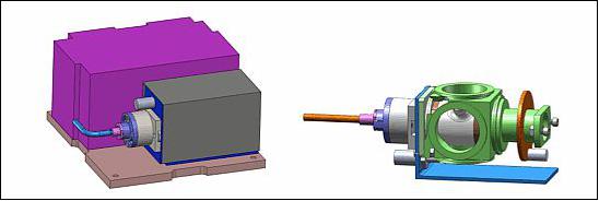
With a stability of <10 pT, the CVHM provides a significant improvement on previously flown CubeSat magnetometers. As the two INSPIRE spacecraft separate from each other after deployment from the P-POD, the magnetometer measurements will provide fine-grain, high fidelity measurements of the solar wind, providing a new look into turbulence effects. Depending upon trajectory (expected Earth-leading or Earth-trailing), the magnetometers may also provide a real-time gradient look across the bow-shock of Earth's magnetosphere during the mission.
The small size of the magnetometer makes it ideal for use on both large and small missions in the future, while remaining "science-grade". Extensive work is being carried out to enable accurate measurements within this small formfactor.
By measuring the solar-wind fine structure, these CVHMs demonstrate directly the science utility of nanospacecraft platforms in deep space: the pair make synchronous measurements of the solar-wind magnetic field as they slowly separate, starting almost immediately upon launch but then continuing for 90 days out to 1.5 million km from Earth. Instrument performance from the low-cost CubeSat bus is characterized both before and after deployment, and during long, "electrically quiet" operating periods.
HPPP (High Powered Payload Processor)
The CalPoly / Tyvak processing board will also fly on the INSPIRE spacecraft, with software derived from the IPEX CubeSat mission. This agile-science software will allow for advanced processing of images and magnetometer data to streamline downlink and increase science return. The processing system (otherwise known as the Intrepid system board), will also support a small imager, with a goal of taking images of the other spacecraft, the Earth and the Moon. This processor will be monitored by the primary INSPIRE systems and reset as needed to mitigate latch-up conditions. The high powered processor provides capabilities for onboard science data processing, backup C&DH functionality (though not implemented on INSPIRE), and additional telemetry sensors to monitor the spacecraft (Ref. 5).
Ground Segment
Some background: INSPIRE is operating far beyond the distance to the Moon and this significant increase in telecommunications range makes the existing CubeSat communications infrastructure unable to meet the mission's needs. Instead of the usual UHF stations, INSPIRE will use NASA's 34 m DSN (Deep Space Network) stations with deep space X-band frequencies. The interfaces and capabilities of the DSN drive the mission to use different GDS (Ground Data System) software from traditional CubeSat missions. Other CubeSat missions operating in deep space, or requiring high data rates in LEO, would also benefit from using NASA's tracking assets and stations. AMPCS (Multimission Data Processing and Control System) provides an interface to these NASA stations and a complete suite of tools for telemetry processing, monitoring, analysis, archival, and spacecraft commanding.
The use of the DSN requires the spacecraft to communicate with the ground command and telemetry software using the CCSDS (Consultative Committee for Space Data Systems) communication protocols. INSPIRE has chosen to use the AMMOS (Advanced Multimission Operation System) and AMPCS of NASA/JPL to command and monitor their spacecraft. 10)
AMPCS is a reusable, multimission ground data processing, archival, visualization, and command system used for spacecraft testing and mission operations. AMPCS is being developed by the MGSS (Multimission Ground Systems and Services) organization of JPL and is being used by several NASA missions, including the flagship MSL (Mars Science Laboratory), the SMAP (Soil Moisture Active Passive) Earth orbiter, and the InSight (Interior Exploration using Seismic Investigations, Geodesy and Heat Transport) Mars lander.
As the first mission to send CubeSats beyond low-Earth orbit, INSPIRE is seeking to leverage the millions of dollars already spent on the research, development, and testing of AMPCS in order to bring value to the mission while lowering risks and costs. JPL's MGSS is spearheading the effort to provide the INSPIRE mission with an existing, proven, and reliable GDS in a low-cost manner.
AMPCS design overview: Figure 9 depicts the top level AMPCS design. For Downlink processing, raw telemetry from the spacecraft is received by AMPCS in the form of CCSDS formatted frames or packets into the Downlink Processing block. The Downlink Processing block transforms the raw telemetry into science and engineering data products, channelized data, EVRs (Event Records), channels in alarm, and log/status messages. These telemetry products are sent to the Message Bus for real time notification of telemetry product availability and to the AMPCS database, along with the original frames and packets for LOM (Life of Mission) storage. The downlink processor is able to ingest frames or packets from any NASA station, data streams or files, or directly from the AMPCS database.
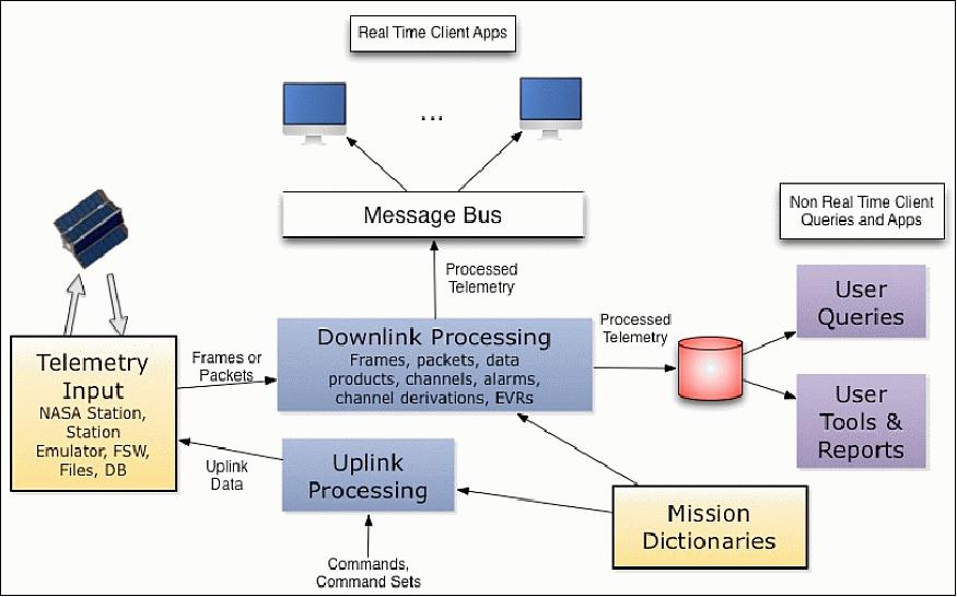
Real time clients receive notification of telemetry availability from the AMPCS Message Bus. These clients can be real time channel visualization clients, simple message bus listeners, Web clients or any user developed application that needs to ingest real time telemetry products. AMPCS has a built-in, Java based monitor providing extensive telemetry visualization capabilities. Visualization of frame, packet and product quality is also provided. Non-real time users access the AMPCS database through a standardized set of APIs (Application Programming Interfaces). AMPCS provides built-in queries and reports to provide users with a base level of capabilities. Spacecraft teams typically develop their own sets of tools that access the AMPCS database through the provided APIs.
For uplink control, AMPCS provides an interface to the NASA station during mission operations and to the missions testbed during the mission's development phases. During mission operations, uplink flow management is provided, as well as the ability to send single commands, command sets and binary files, i.e., new FSW (Flight Software) images, to the spacecraft.
AMPCS also provides two levels of automation. During spacecraft testing, session based automation is provided through AMPCS enabled Python scripts. For example, a script can send a command to the spacecraft and wait for a response in the telemetry from the spacecraft before sending the next command. In this way, repeatable test scripts can be developed and used throughout the mission's lifecycle. The other level of automation provided is during mission operations, when the need for cross-session automation is necessary. This capability enables "Lights Out" automation for a mission.
In conclusion, the MGSS (Multimission Ground Systems and Services) and INSPIRE partnership at JPL resulted in a novel methodology to develop low-cost space missions. Instead of having the development of the flight system drive the development or the adaptation of the ground system, the project viewed the FSW (Flight Software) and GDS (Ground Data System) as two loosely-coupled modules in a larger system. By adhering to standards and defining clean, concise interfaces, the project was able to completely insulate the modules from one another without compromising their ability to work together. As a result, MGSS was able to provide INSPIRE with a cutting-edge command and telemetry system at a very low cost.
References
1) Brent Sherwood, Sara Spangelo, Andreas Frick, Julie Castillo-Rogez, Andrew Klesh, E. Jay Wyatt, Kim Reh, John Baker, "Planetary CubeSats come of age," Proceedings of the 66th International Astronautical Congress (IAC 2015), Jerusalem, Israel, Oct.12-16, 2015, paper: IAC-15-A3.5.8
2) "Interplanetary Nano-Spacecraft Pathfinder in Relevant Environment (INSPIRE)," NASA/JPL, URL: http://www.jpl.nasa.gov/cubesat/missions/inspire.php
3) http://www.lewiscenter.org/Global-Programs/GAVRT/index.php
4) Andrew Klesh, Lauren Halatek, "INSPIRE: Interplanetary NanoSpacecraft Pathfinder In a Relevant Environment," 10th Annual CubeSat Developers' Workshop 2013, Cal Poly, San Luis Obispo, April 24-26, 2013, URL: http://www.lcpm10.caltech.edu/pdf/session-6/1_LCPM_INSPIRE_2013.pdf
5) Andrew Klesh, John Baker, Julie Castillo-Rogez, Lauren Halatek, Neil Murphy, Carol Raymond, Brent Sherwood, John Bellardo, James Cutler, Glenn Lightsey, "INSPIRE: Interplanetary NanoSpacecraft Pathfinder In Relevant Environment," Proceedings of the 27th AIAA/USU Conference, Small Satellite Constellations, Logan, Utah, USA, Aug. 10-15, 2013, paper: SSC13-XI-8, URL: http://digitalcommons.usu.edu/cgi/viewcontent.cgi?article=2992&context=smallsat
6) "INSPIRE (Interplanetary NanoSpacecraft Pathfinder In a Relevant Environment)," Proceedings of the 11th Annual CubeSat Developers' Workshop - The Edge of Exploration," San Luis Obispo, CA, USA, April 23-25, 2014, URL: http://www.cubesat.org/images/cubesat/presentations/DevelopersWorkshop
2014/Klesh_INSPIRE.pdf
7) "NASA Announces New CubeSat Space Mission Candidates," NASA/JPL. Feb. 26, 2013, URL: http://www.jpl.nasa.gov/news/news.php?release=2013-073
8) Scott Palo, George Stafford, Alan Hoskins, "An Agile Multi-use Nano Star Camera for Constellation Applications," Proceedings of the 27th AIAA/USU Conference, Small Satellite Constellations, Logan, Utah, USA, Aug. 10-15, 2013, paper: SSC13-III-5, URL: http://digitalcommons.usu.edu/cgi/viewcontent.cgi?article=2928&context=smallsat
9) Courtney B. Duncan, Amy E. Smith, Fernando H. Aguirre, "Iris Transponder – Communications and Navigation for Deep Space," Proceedings of the AIAA/USU Conference on Small Satellites, Logan, Utah, USA, August 2-7, 2014, paper: SSC14-IX-3, URL: http://digitalcommons.usu.edu/smallsat/2014/AdvTechComm/3
10) William L. Quach, Lloyd R. DeForrest, Andrew T. Klesh, Joshua B. Schoolcraft, "Adapting a Large-Scale Multi-Mission Ground System for Low-Cost CubeSats," SpaceOps 2014, 13th International Conference on Space Operations, Pasadena, CA, USA, May 5-9, 2014, URL: http://arc.aiaa.org/doi/pdf/10.2514/6.2014-1634
The information compiled and edited in this article was provided by Herbert J. Kramer from his documentation of: "Observation of the Earth and Its Environment: Survey of Missions and Sensors" (Springer Verlag) as well as many other sources after the publication of the 4th edition in 2002. - Comments and corrections to this article are always welcome for further updates (eoportal@symbios.space).
Overview Spacecraft Launch Sensor Complement Ground Segment References Back to top