INSAT-2 (Indian National Satellite-2)
EO
Atmosphere
Ocean
Cloud type, amount and cloud top temperature
Starting with the launch of INSAT-2A in July 1992, INSAT-2 (Indian National Satellite- 2) was a series of five multipurpose geostationary satellites for telecommunications, television broadcasting, meteorology and search & rescue services. INSAT-2 was owned and operated by ISRO (Indian Space Research Organisation), in collaboration with various Indian government departments: DOS (Department of Space), DOT (Department of Telecommunications), IMD (Indian Meteorological Department), and AIR (All India Radio). INSAT-2 left service in May 2011.
Quick facts
Overview
| Mission type | EO |
| Agency | ISRO |
| Mission status | Mission complete |
| Launch date | 30 Aug 1983 |
| End of life date | 22 Nov 1989 |
| Measurement domain | Atmosphere, Ocean, Land |
| Measurement category | Cloud type, amount and cloud top temperature, Liquid water and precipitation rate, Radiation budget, Multi-purpose imagery (land), Surface temperature (land), Albedo and reflectance, Surface temperature (ocean), Atmospheric Winds |
| Measurement detailed | Precipitation intensity at the surface (liquid or solid), Cloud type, Land surface imagery, Upward long-wave irradiance at TOA, Earth surface albedo, Land surface temperature, Sea surface temperature, Wind profile (horizontal) |
| Instruments | VHRR, CCD camera |
| Instrument type | Imaging multi-spectral radiometers (vis/IR) |
| CEOS EO Handbook | See INSAT-2 (Indian National Satellite-2) summary |
Summary
Mission Capabilities
All INSAT-2 satellites consisted of a single sensor, VHRR (Very High Resolution Radiometer), with the exception of INSAT-2C, which consisted solely of a communications payload. VHRR was a whiskbroom radiometer, that provided multi-purpose imagery and wind derivation through the tracking of clouds and water vapour features.
Performance Specifications
VHRR operated in two spectral ranges, 0.55- 0.75 µm (VIS/Visible band) and 10.5- 12.5 µm (TIR/Thermal Infrared band). The instrument had a spatial resolution of 2 km when imaging in VIS band, and 8 km in TIR. VHRR operated in three modes, Full scan mode, wherein the entire Earth disc would be imaged, with a Field of View (FOV) of 20° x 20°, Normal scan mode, allowing coverage of at least 50º N to 40º S latitude, and sector scan mode, allowing scanning of a designated sector on the Earth disc.
All of the INSAT-2 satellites operated in a geostationary orbit, with an altitude of 35,786 km. INSAT-2A was positioned at 74°E, -2B, -2C and -2D at 93.5°E and -2E at 83°E.
Space and Hardware Components
INSAT-2 carried two additional hardware systems across its five satellites, the Data Collection System (DCS) and SASAR (Satellite Aided Search and Rescue) system. The DCS contained a data relay transponder (DRT) for environmental data collection from DCPs (Data Collection Platforms). It had a bit rate of 2.8 kbit/s, with an uplink frequency of 402.75 MHz, and a downlink frequency of 4504.1 MHz. SASAR allowed emergency alert capabilities for the Indian subcontinent, as part of the international COSPAS-SARSAT satellite search and rescue program. The INSAT-2 buses were considered to be the second generation of those used in the series’ predecessor, INSAT-1 and used a box-shaped structure based around a central cylinder of 0.89 m diameter with asymmetrical five-panel solar wings (23 m span). INSAT-2 buses were 3- axis stabilised, with a design life of 12 years.
INSAT-2 (Indian National Satellite-2) Series
The INSAT system of ISRO (Indian Space Research Organization) is a multipurpose geostationary satellite system for telecommunications, television broadcasting, meteorology and search & rescue services. The overall objective of the INSAT meteorological program is to provide round-the-clock surveillance service of weather systems including severe weather events around the Indian region. Commissioned in 1983, INSAT was and is also one of the largest domestic communication systems in the Asia-Pacific Region.
Background on Program Start
The INSAT (Indian National Satellite) system is a joint venture, conceived in the 1970s, of the following departments/agencies of the government of India: DOS (Department of Space), DOT (Department of Telecommunications), IMD (Indian Meteorological Department), AIR (All India Radio). DOS is responsible for the operation of the INSAT space segment. IMD operates a Meteorological Data Utilization Center (MDUC, at Delhi) for the dissemination and distribution of INSAT meteorological images and ancillary data. 1) 2)
In this context, the INSAT-1 series services were employed for meteorological observations over India and the Indian Ocean, as well as for domestic telecommunications (nationwide direct TV broadcasting, TV program distribution, meteorological data distribution, etc.). The INSAT-1 series satellites were all built by Ford Aerospace Corporation (USA) to Indian specifications. The S/C had a mass 650 kg on station and carried twelve 6/4 GHz transponders with an output power of 4.5 W and three (two active plus one backup) 6/2.5 GHz transponders.
The meteorological payload of the INSAT-1 series consisted of VHRR (Very High-Resolution Radiometer). Spectral ranges: 0.55 - 0.75 µm (VIS) and 10.5 - 12.5 µm (IR). Resolutions: 2.75 km for VIS and 11 km for IR channels, respectively. Scanning time/image = 30 minutes. In addition, the INSAT-1 series flew DCS (Data Collection System) with the objective to collect and relay environmental data (meteorological, hydrological and oceanographic) from unattended land- and ocean-based automatic data collection platforms (DCPs).
Mission | Comment |
INSAT-1A | Launch: April 1982 on a Delta-3920 launch vehicle; INSAT 1A was lost due to malfunctions within 18 months of launch. |
INSAT-1B | Launch: Aug. 30, 1983 on Space Shuttle flight STS-8; S/C position: 74º East; the satellite is used as a standby for INSAT-1D. |
INSAT-1C | Launch: July 22, 1988 on Ariane-3 from Kourou. The satellite lost Earth lock on Nov. 22, 1989 and is inoperable since then. |
INSAT-1D | Launch: June 12, 1990 on a Delta-2 vehicle; S/C position: 74º E , INSAT-1D was deactivated on May 14, 2002 - after providing useful services for about 12 years. |
INSAT-2 Series
The second and subsequent generation satellites were designed and built indigenously. The INSAT-2 series was conceived with five spacecraft INSAT-2A through -2E, with the first two, INSAT-2A and INSAT-2B, planned to be realized as multipurpose satellites on the lines of the INSAT-1 system. 3)
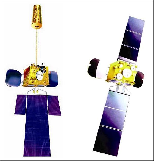
To meet the user community demands, the next two satellites, INSAT-2C and INSAT-2D were reconfigured as exclusive communication satellites (Figure 1).
INSAT-2E satellite, the last of the second generation INSAT-2 series, was evolved as the forerunner for the future INSAT-3 bus. INSAT-2E offered 17 communication transponders with near hemispherical and zonal coverage in addition to 3-channel VHRR and CCD camera payload providing improved resolution in both visible and infrared bands.
Each INSAT-2 (and higher) series satellite is the product of the well-orchestrated effort of the following major centers of ISRO:
• ISAC (ISRO Satellite Center), Bangalore, India; S/C design, manufacture, testing, and integration (also development of S/C subsystems)
• SAC (Space Application Center), Ahmedabad, development of instruments in particular meteorological payloads
• ISTRAC (ISRO Telemetry, Tracking and Command Network), a network of ground stations at Bangalore, Lucknow, Port Blair, Sriharikota, Thiruvananthapuram. Besides, ISTRAC has TT&C stations at Mauritius, Bearslake (Russia), Biak (Indonesia) and Brunei. A multimission Spacecraft Control Centre is located at Bangalore.
• SHAR (Sriharikota Launching Range), Andhra Pradesh, main ISRO launch site located on India's east coast at 13.9º N, 80.4º E, about 100 km north of Chennai. SHAR covers a total area of about 145 km2) with a coastal length of 27km. The range became operational in 1971. In 2002, SHAR has been renamed to “Satish Dhawan Space Center, SHAR (SDSC-SHAR)” in honor of the former chairman of the space commission, a pioneer of India's space program.
• VSSC (Vikram Sarabhai Space Center), Trivandrum, Kerela State; development of launch vehicles, PSLV, etc.

Spacecraft
The INSAT-2 program at ISRO was underway in 1983 to develop an indigenous multi-purpose GEO spacecraft that relied heavily on the previous Ford Aerospace design. The INSAT-2 satellite family is considered the second generation INSAT series for the nineties, designed and developed by ISRO (Indian Space Research Organization). Like the INSAT-1 series, the INSAT-2 series is a multi-purpose satellite family for telecommunication, television broadcasting and meteorological services.
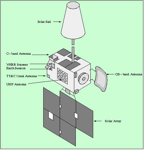
The S/C is three-axis stabilized (momentum-biased) and uses a box-shaped structure based around a central cylinder of 0.89 m diameter with asymmetrical five-panel solar wings (23 m span). Power = 1.18 kW (EOL). Orbit maneuvers are supported by an integral apogee boost motor, there are also 16 attitude control thrusters. On-orbit mass is 911 kg.
The INSAT-2 operational satellites have enhanced capabilities (over the INSAT-1 series). The INSAT-2 meteorological sensor VHRR has a 2 km resolution in VIS and 8 km resolution in the IR spectral ranges.
The INSAT-2C launch with Ariane occurred on Dec. 6, 1995, the INSAT-2D launch with Ariane 44L occurred on June 3, 1997 (along with Inmarsat 3F4), the INSAT-2E launch took place on April 2, 1999. The meteorological instrument on the INSAT-2E spacecraft features an additional band in the water vapor absorption spectrum of 6.8 µm.
Mission | Comment | Payload (meteorological) | Power, Battery |
INSAT-2A | Launch: July 9, 1992, Ariane-4, at 74º E, | VHRR, DCS, SASAR | 1.16 kW summer solstice NiCd, 18 Ah, 28 cells |
INSAT-2B | Launch: July 22, 1993, Ariane-4, at 93.5º E, Launch mass = 1906 kg, dry mass = 916 kg | VHRR, DCS, SASAR | ~1 kW |
INSAT-2C | Launch: Dec. 6, 1995, Ariane-4, at 93.5º E, | communications payload only | 1.735 kW, summer solstice NiCd, 24 Ah, 28 cells |
INSAT-2D | Launch: June 3, 1997, Ariane 44L, at 93.5º E, | VHRR, DCS, SASAR | Power bus anomaly in October 1997 |
INSAT-2DT | In January 1998, a transponder was leased from ArabSat-1C to continue the INSAT-2D communication services to the users | ||
INSAT-2E | Launch: Apr. 2, 1999 (UTC), Ariane 4, at 83º E, | VHRR, CCD Camera, DCS, SASAR | 2.5 kW at equinox |
Sensor Complement
Note: Only the meteorological instruments and service payloads are described (not the communication payloads). ISRO is very reluctant to provide any operational status of the various missions; hence, no mission status of the INSAT-2 series can be provided.
VHRR (Very High-Resolution Radiometer)
VHRR was designed and built at ISRO. VHRR is an improved version over that of the INSAT-1 series. The instrument can be operated in any one of the following modes: 4)
• Full scan mode (20º x 20º): This covers the entire Earth disk and some space around in 33 minutes (can be positioned in steps of 0.35º in east-west direction).
• Normal scan mode: Coverage of at least 50º N to 40º S latitude (in 23 minutes)
• Sector scan mode: The sector can be positioned anywhere in the Earth disk along the N-S direction (in 7.2 minutes). 5)
The VHRR instrument consists of three packages: the EOM (Electrooptics Module), the electronics package-1, and the electronics package-2. The electrooptics module houses the scan assembly, the optics assembly, and the radiant cooler assembly. The VIS and IR detectors with their amplifiers are also part of the electrooptics module. The electronics package-1 contains the signal processors for all channels, data formatter, power distribution, and timing logic circuits. The scanner electronics, the DC/DC converter regulators, patch temperature controller and the analog telemetry processor are part of the electronics package-2.
VHRR is a whiskbroom type imager with a telescope of 20 cm diameter. The optical subsystem uses an all-reflective Ritchey-Chretien telescope (folded optics, the primary mirror is a concave hyperboloid with an aperture of 202 mm and f/2.0, the secondary mirror is a convex hyperboloid with an aperture of 62 mm; focal length of the system is 1594 mm). The convergent light beam, reflected from the secondary mirror, is incident on the dichroic beam splitter which is mounted at 45º to the telescope axis.
The VIS radition uses two arrays of four silicon photodiodes each providing a 2 km resolution at nadir (scan mirror is oscillating is 0.5 Hz). The IR detector assembly consists of two HgCdTe photoconductive detectors mounted in the passive radiant cooler. The IR detector is operated at 105 K. The scan mirror is mounted on a two-axis gimballed scan structure which generates 2-D images by sweeping the detector IFOV in the E-W and N-S directions. Each E-W/W-E scan generates one IR line of 8 km width and four VIS lines each of 2 km width.
Spectral band: VIS | 0.55 - 0.75 µm; Integrated out-of-band response <3% |
Spatial resolution VIS | 56 µrad (or 2 km x 2 km) |
Radiometric performance: SNR | >6 for VIS at 2.5% albedo |
Dynamic range of IR channel | 4-340 K |
Misregistration between VIS and TIR | <56 µrad |
Modulation Transfer Function (MTF) | >21% for TIR; >23% for VIS channel |
INSAT VHRR Data Distribution: The INSAT-1/2 VHRR data is distributed in near realtime to/from 22 SDUCs (Secondary Data Utilization Centers) throughout the country.
DCS (Data Collection System)
The INSAT-2 series flies a data collection system (DCS) with a data relay transponder (DRT) for environmental data collection from DCPs (Data Collection Platforms) the ground segment. The characteristics of the DCPs are:
- Frequency of transmission: 402.75 MHz (uplink)
- Downlink frequency: 4504.1 MHz
- Bit rate: 4.8 kbit/s
- EIRP (uplink): 16.5 dBW
- Mode of transmission: Burst mode
- Burst length 87 milliseconds
- Number of sensor 10 (7 analog & 3 digital)
- Number of bits in one frame: 422 bits
SASAR (Satellite Aided Search and Rescue) System
SASAR provides an emergency alert capability for the Indian subcontinent and beyond as part of the international satellite aided search and rescue program. India has signed an agreement with the international COSPAS-S&RSAT council for the use and operation of LUTs (Local User Terminals) and a MCC in Bangalore and Lucknow. Both LUTs provide substantial coverage of the Indian Ocean region as well as neighboring countries: Bangladesh, Bhutan, Maldives, Nepal, Sri Lanka, Seychelles and Tanzania. 6)
All INSAT series satellites (GEO) are being operated by the MCF (Master Control Facility) at Hassan in Karnataka, India. MCF is responsible for initial orbit raising of satellites, in-orbit testing, and on-orbit operations of these satellites. It also carries out special operations, including stationkeeping maneuvers and recovery actions in case of contingencies.
INSAT-2E Mission
Spacecraft
General description of the INSAT-2E satellite bus system. The S/C mass at launch is 2550 kg (dry mass of 1146 kg). The S/C power is 2.5 kW at equinox provided by solar panels with an area of 20.52 m2 (GaAs solar cells). Battery: NiH2, 60 Ah, 27 cells. The S/C design life is 12 years. The INSAT-2E communication payload carries 17 transponders, 12 operating in the normal C-band frequency and five in the lower extended C-band. Seven of the normal C-band transponders have wide beam coverage, the remaining ten have zonal coverages. 7)
S/C Structure
• The S/C main body is a cuboid of dimension: 1930 mm x 1770 mm x 2375 mm. The deployed S/C length is 25.78 m.
• The main cylinder of 1175 mm diameter and 2375 mm length accommodates fuel and oxidizer tanks
• North & south equipment panels are of size 2300 mm x 1930 mm. They are attached to the main cylinder using shear frames
• Cutouts are provided for the solar array drive assembly on the south deck and for the solar sail on the north deck
S/C Mechanisms
• Deployment mechanisms include single-sided solar panel, solar sail and shaped reflectors
• Two flaps offsetting seasonal variations in solar pressure; it is operated by a shaped memory alloy spring
Thermal System
• The thermal design requires heat dissipation of about 1700 W
• Use of embedded heat pipes adopted to optimize the thermal system mass
• The thermal control system is complemented by the use of optical solar reflectors, multi-layer insulation blankets, thermal coatings, thermal tapes and heaters
• Appropriate thermal management for NiH2 battery to maintain its temperature between ±10ºC.
Power System
• Single-sided deployable solar array (GaAs/Ge cells) on the south side of the S/C with four panels of size: 2.7 m x 1.9 m
• EOL power of 2143 W
• Two 60 Ah NiH2 batteries provide the eclipse requirement of 1800 W for full communication payload operation
• Two independent power buses with cross-strap capability, each bus regulated to 42+0.5 V by sequential switching
• Bus selection scheme provided for platform subsystems
Telemetry, Tracking and Command (TT&C) System
• C-band telemetry and telecommand links with the subsystems deriving their heritage from earlier INSAT-2 S/C
• Near omni radio visibility during transfer orbit phase
• Normal and dwell mode telemetry possible by ground command
• Simultaneous dwelling on any of the 16 channels
• The system is capable of providing 2048 on/off commands and 64 data commands
• Provision of variable execution pulse width command feature
• The ranging accuracy is 50 m during transfer orbit and 30 m during on-orbit phase
Attitude and Orbit Control System (AOCS)
• The AOCS subsystem is comprised of microprocessor-based electronics (Mil-Std-1750A), attitude sensors, inertial reference unit, momentum/reaction wheels, magnetic torquer, solar flap and RCS (Reaction Control System) thrusters
• The propulsion system uses bi-propellants with 440 N LAM (Liquid Apogee Motor) for orbit raising and a total of 16 RCS thrusters for orbit and attitude control (fuel for a mission life of 12 years). Anti Earth viewing thrusters provide a backup for LAM
• The attitude sensor configuration supports all requirements. The north-facing Earth sensor is used during transfer orbit to maintain Earth lock. Redundant Earth sensors serve the same purpose during the on-orbit phase. The digital sun sensor, used in the transfer orbit, has a FOV of 37º. Four CASS (Coarse Analog Sun Sensors) are used, four Pi sun sensors are backup for CASS.
• AOCS pointing accuracies: pitch and roll = 0.2º, yaw = 0.4º
• Some special features of AOCS are:
- Fault detection and identification logic for change over to redundant system
- Safe mode operation in case of Earth lock loss
- Long pulse detection logic which prevents unduly long during thruster firing
- Remote programming for unforeseen requirements
- Inertial reference unit with three gyros in orthogonal axis provide accumulated angle and rate information
- Two momentum wheels provide stiffness to the S/C along the pitch axis. Redundancy for one wheel failure is provided by the reaction wheel along the yaw axis.
Launch
The INSAT-2E spacecraft was launched on Ariane-42P launcher from Kourou on April 2, 1999 (UTC). 8) 9)
Orbit: Geostationary orbit, altitude ~35.786 km, location at 83º eastern longitude.
Status of VHRR/2 Instrument
• In April 2012, after 13 years of satisfactory communication service, INSAT-2E, the last of the five satellites in the INSAT-2 series, has successfully completed its mission life. 10)
• The INSAT-2E spacecraft along with the communication payload remained operational - while the meteorological payload in GEO, VHRR/2, was not functioning anymore. As a consequence, ISRO prepared immediately a replacement mission, a smaller spacecraft with another VHRR/2 instrument for launch into GEO. This mission was named MetSat-1 and was launched on Sept. 12, 2002. After the Space Shuttle Columbia accident (Jan. 31, Feb.1, 2003), the Government of India and ISRO renamed the MetSat-1 spacecraft to Kalpana-1 in honor of Kalpana Chawla (a native of India), who died as a NASA astronaut in the Columbia accident.
• The VHRR/2 instrument of INSAT-2E failed already in 1999. 11)
Meteorological Payload of INSAT-2E
VHRR/2 (Very High Resolution Radiometer)
This ISRO whiskbroom-type imager is an enhanced version of the two-band VHRR flown on INSAT-2A/2B. A third band was added, the water vapor band [MWIR (Mid-Wave Infrared)], which is flown on the INSAT-2E spacecraft for the first time. The water vapor band is used for estimating water-vapor-tracer winds at the mid-troposphere, identifying subsidence/convection zones, and indirectly estimating the atmospheric correction to SST (Sea Surface Temperature) for the TIR channel. 12) 13) 14)
Spectral band: VIS | 0.55 - 0.75 µm; Integrated out-of-band response <3% |
Spatial resolution VIS | 56 µrad (or 2 km x 2 km) |
Radiometric performance: SNR | > 6 for VIS at 2.5% albedo |
Dynamic range of TIR/MWIR channels | 4-340 K |
Misregistration between VIS and IR | < 56 µrad |
Modulation Transfer Function (MTF) | > 21% for IR and TIR; >23% for VIS channel |
VHRR/2 consists of the following major subsystems: scan mechanism assembly, radiant cooler, Optics assembly, and camera electronics.
• Scan mechanism assembly: The scanner consists of a two-axis gimbal-mounted beryllium mirror. The gimbal is servo-driven in two orthogonal axes. The mirror swings mechanically ±5º /s (E-W fast scan) to provide an optical sweep of 20º (N-S) to the detector FOV to generate one line/s. In the other axis (N-S), the mirror is stepped through 224 µrad for each scanning line. In addition to the 20º (N-S) stepping, there is a provision to rotate the mirror through 90º to view the blackbody. There is also an offset capability in the E-W direction to position the Earth disk at the center of the image for longitudinal S/C positions between 70-100º E.
• Radiant cooler. A passive system is used to cool the infrared detectors to an operating temperature of 105-115 K.
• Optics assembly: The system consists of a telescope, dichroic beam splitter, infrared collimating lens, infrared relay optics, and VIS band optical elements. The telescope is a Ritchey-Chretien type instrument with a 200 mm diameter concave hyperboloid primary mirror and a 56 mm diameter secondary mirror, the separation distance is 285 mm. The convergent radiation beam from the secondary mirror is intercepted by a dichroic mirror which reflects 85% of IR energy and transmits 75% of the visible energy without distortion of the wavefront. The transmitted VIS band energy is reflected by a fold mirror onto an array of CCD detectors, while the reflected IR energy is collimated prior to exiting the telescope. This permits independent performance optimization of the TIR and IR (water vapor) bands in the radiant cooler/detector system.
• Camera electronics: The subsystem provides the following functions: a) digitization of the detector outputs, b) control of the IR detector temperatures, c) generation of clock and other control pulses, d) formatting of data, and e) instrument monitoring. The source data is coregistered and digitized to 10 bits.
The 2-D image of the Earth is generated by sweeping the IFOV of the detectors by rotation of the scan-mirror gimbals in two orthogonal axes. For every sweep of the mirror, four contiguous lines of VIS, and one line of TIR and IR bands each, are generated in the E-W direction. At the end of a sweep, the mirror is stepped south through an angle equivalent to eight km in ground distance. Three operational modes are provided:
• Full frame mode. An image of 20º x 20º (TFOV) is generated within 33 minutes, covering the full disk of the Earth.
• Normal fram mode: Same coverage in E-W direction as in full frame mode; however, the N-S scan is 14º covering latitudes from 50º to 40º S in 23 minutes.
• Sector frame mode: This capability provides 4.5º coverage in N-S direction (about 2800 km with 351 scan lines) in 7.2 minutes. The E-W extent remains unchanged as in full and normal frame modes. The sector may be positioned anywhere within TFOV in steps of 0.5º (312 km or 39 lines) in N-S direction.
Instrument calibration: cold space views at the east/west ends are used for establishing reference radiance for all three bands. A full calibration of the TIR and IR bands is provided by swinging the mirror to view a blackbody cavity.
CCD Camera
The experimental instrument uses a linear CCD detector array with three spectral bands (see Table 5). Applications of the instrument data are in meteorology as well as in vegetation mapping. Of the three bands, the first two being similar to the NOAA AVHRR bands 1 and 2, provide “vegetation index” observation; the third band is used for snow-cover, snow-cloud discrimination and for aerosol measurements. A linear silicon array is used for the VIS and VNIR bands, while a InGaAs array is used for the SWIR band. The camera provides a nadir spatial resolution of <= 1 km in all three bands. The swath of the CCD Camera is 6300 km. The source data is coregistered and digitized to 10 bits. The data rate of the CCD Camera is 1.3 Mbit/s (QPSK modulation).
The CCD Camera is a first-time introduction on INSAT-2E. It permits greater accuracy in cyclone tracking and also affords monitoring of local severe storms. Plans for the third-generation INSAT series call for a tandem operation, in which two members, INSAT-3A and -3D are earmarked for meteorology. While the INSAT-3A meteorological payload is still very similar to that flown on INSAT-2E (VHRR/2), the INSAT-3D payload will feature an enhanced VHRR instrument with six channels and a higher spatial resolution; two of the channels provide a split window for the TIR bands at 10.3-11.3 µm and 11.5-12.5 µm. This feature will be used to improve SST estimates.
Spectral bands | 0.62 - 0.68 µm,VIS band |
Spatial resolution | 1 km x 1 km |
MTF | <=0.23 |
Dynamic range | 0-100% albedo |
Noise performance | SNR <= 128 at 100% albedo |
Coverage | 6250 km x 300 km per scan line (max. number of lines = 31) |
Image repetivity | One scan line per minute |
Instrument mass, power | <55 kg, <50 W |
The CCD Camera consists of the following elements: scan mechanism assembly, optics and detector assembly, and camera electronics.
• Scan mechanism assembly: Features a gimballed scan mirror which sweeps FOV in two orthogonal axes. The fast sweep generates 300 video lines over a 6300 km east-west direction every minute (with a fast retrace capability). The 0.4º south stepping of the mirror after each east-west scan provides the generation of successive image strips. The TFOV (Total Field of View) of the mirror is ±13º in the E-W and ±10º in the N-S direction, while the actual image is ±5º in E-W and ±5º in the N-S direction. The actual image may be positioned anywhere within the mirror TFOV.
• Optics and detector assembly: The assembly consists of the scan mirror, telescope, dichroic beam splitters, fold mirror, lens doublet and bandpass filters. The front-end optics, namely scan mechanism and telescope, is identical to that of VHRR (except that the telescope performance has been upgraded to provide a FOV of ±0.25º at twice the spatial frequency of VHRR). The VIS and VNIR silicon CCD detectors have 2048 element linear arrays, as well as the InGaAs photodiode detector (cooled) for the SWIR band. The outputs of the three line arrays, providing a total of 900 pixels, are processed to construct 300 image pixels for each band.
• Camera electronics: The subsystem provides: a) clock and bias inputs to the detectors, b) processes and digitizes the detector outputs., c) formats the video signal along with auxiliary information, d) monitors the instrument; e) interfaces with other subsystems, and f) controls the SWIR detector temperature through a feedback loop.
Meteorological Payload Data Transmission
The VHRR data in PCM NRZ-S format is BPSK modulated, the data rate is 526.5 kbit/s. The data of the CCD Camera in PCM NRZ-L format is QPSK modulated, the data rate is 1.3 Mbit/s. Both meteorological payloads have a common up convertor and a redundant transmitter for a downlink through a 4.5 GHz carrier. A separate 0.9 m diameter Earth view antenna on-board the S/C is providing transmission services for the meteorological data.
Data from the INSAT series instruments are acquired, processed and disseminated by IMD (India Meteorological Department), the main data center and operator the INSAT series. A DCS (Data Collection System) is flown on all INSATs for collecting and relaying data from platforms in the ground segment.
Total number of channels | 17 |
Normal C-band channels | 12 |
Lower extended C-band channels | 5 |
Downlink coverage: | Wide beam (channel 6, 8, 10, 12, 14, 15, and 17), zonal beam all other channels |
Transmit EIRP | 36 dBW for all channels |
RF output power | 60 W (wide beam); 32 W (zonal beam) |
Communication Payload of INSAT-2E
Under an agreement with Intelsat (International Telecommunications Satellite Organization), eleven 36 MHz equivalent units of C-band capacity on INSAT-2E have been leased to Intelsat.
INSAT Data Availability and Indo-US Data Exchange Center
On December 16, 1997 a major shift in ISRO data policy occurred when representatives of NASA, NOAA and ISRO signed an agreement in a Washington DC meeting, for ISRO to provide full-sized INSAT weather data to the world meteorological community in digital format and without delay. The agreement calls also for the USA to make Earth and atmospheric data available to India (i.e. GOES series data). 15) 16)
Under the bilateral program of cooperation with USA, an Indo-US Data Exchange Center has been established at IMD (India Meteorological Department), New Delhi in November 1999 for the exchange of meteorological satellite data with USA. Processed INSAT imagery data is being transmitted every three hours to NOAA. In return, GOES imagery data is being transferred to IMD, India. The data exchange takes place through dedicated communication links.
Under another collaborative program with EUMETSAT, an agreement has been signed for reception of METEOSAT data at IMD, New Delhi. Accordingly, a METEOSAT ground receiving station, referred to as PDUS (Primary Data User Station), was installed in early 2000 at IMD, New Delhi, to receive high-resolution imagery data from the METEOSAT-5 satellite located at 63º E.
Reception of NOAA POES broadcast data: The AVHRR and TOVS data from the NOAA series of polar orbiting satellites are received and processed by IMD at New Delhi and Chennai through HRPT (High Resolution Picture Transmission) receiving stations. The New Delhi HRPT receiving station was upgraded to receive the NOAA (K, L, M, N series) satellite data.
Further Indo-US workshops were held to identify fields of cooperation:
• Indo-US Earth and Atmospheric Workshop held in Washington DC in Dec. 2002.
• Indo-US Conference on Space Science, Applications, and Commerce; Bangalore, India during June 22-25, 2004. 17)
References
1) `Space Applications,' DOS Annual Report 1990-91. pp. 13-23
2) P. Ramachandran, “Second generation Indian national satellite system space segment — INSAT II,” Acta Astronautica, Volume 18, 1988, pp. 309-323
3) V. R. Katti, K. Thyagarajan, K. N. Shankara, A. S. Kiran Kumar, “Spacecraft technology,” Special Section: Indian Space Program, Current Science, Vol. 93, No 12, Dec. 25, 2007, URL: http://www.docstoc.com/docs/102189316/Spacecraft-technology
4) George Joseph, V. S. Iyengar, K. Nagachenchaiah, A. S. Kiran Kumar, B. V. Aradhye, V. N. Kaduskar, R. K. Dave, C. M. Nagrani, “Very high resolution radiometers for INSAT-2,” Current Science, Vol. 66, No. 1, Jan. 10, 1994, pp. 42-56,
5) G. Joseph, et al., “INSAT-2 Very High Resolution Radiometer for Meteorological Observations,” Journal of Spacecraft technology, Vol. IV, No. 1, Jan. 1994, pp. 183-207
6) “India plans S&R Operations for INSAT-3A, to aid land, ship, aircraft users,” Aviation Week & Space Technology, Apr. 8, 2002, p. 32
7) ISRO brochure of INSAT-2E, provided by George Joseph
8) R. Ramachandran, “The promise of INSAT-2E,” Frontline, Volume 16, Issue 8, Apr. 10 - 23, 1999, URL: https://web.archive.org/web/20080919185351/http://www.hinduonnet.com/fline/fl1608/16080040.htm
9) “INSAT-2E ,” ISRO, April 3, 1999, URL: [web source no longer available]
10) “INSAT-2E Completes 13 years of Successful Operation,” ISRO Press Release, April 3, 2012, URL: http://www.isro.gov.in/pressrelease/scripts/pressreleasein.aspx?Apr03b_2012
11) K. S. Jayaraman, “India Approves Nation's 1st Dedicated Weather Satellite,” Space News, Dec. 11, 2000, pp. 3, 20
12) V. S. Iyengar, C. M. Nagrani, et al., “Meteorological imaging instruments on-board INSAT-2E,” Current Science, Vol. 76, No 11, June 10, 1999, pp. 1436-1443
13) R. C. Bhatia, H. V. Gupta, “Use of charged Coupled device payload on INSAT-2E for meteorological and agricultural applications, “ Special Section: INSAT-2E, Current Science, Vol. 76, No 11, June 10, 1999, pp. 1444-1447, URL: [web source no longer available]
14) P. S. Desai, “Satellite Meteorology in India: Accomplishments and Challenges,” Space Forum, Vol. 5, No. 1-3, 2000, pp. 203-216
15) W. Ferster, “Policy Shift Paves Way for India-U.S. Imagery Deal,” Space News, Jan. 5-11, 1998, p. 18
16) Devendra Singh, R. C. Bhatia, “Current and Future Satellite Programs and Systems in India,” ITSC-13 (International TOVS Study Conference), Ste-Adele, Quebec, Canada, Oct. 29, to 4 Nov. 4, 2003, URL: http://cimss.ssec.wisc.edu/itwg/itsc/itsc13/proceedings/session6/6_3_singh.pdf
17) V. R. Katti, R. K. Rajangam, “An Overview of ISRO Satellite Platforms,” India-United States Conference, Bangalore, India, June 21-25, 2004, URL: http://www.pdfio.com/k-381363.html