INDEX / REIMI
EO
JAXA
Operational (extended)
Quick facts
Overview
| Mission type | EO |
| Agency | JAXA |
| Mission status | Operational (extended) |
| Launch date | 23 Aug 2005 |
| CEOS EO Handbook | See INDEX / REIMI summary |
INDEX (Innovative Technology Demonstration Experiment) / REIMEI
Spacecraft Launch Mission Status Sensor Complement References
INDEX is a Japanese microsatellite of JAXA/ISAS (Institute of Space and Astronomical Science). In JAXA tradition, the INDEX spacecraft was renamed to REIMEI after launch - meaning "dawn" in Japanese. The mission objective is to use INDEX as a demonstration satellite of advanced engineering technologies, and to support a small-scale astronomical science mission (fine structural observation of the aurora). 1) 2) 3) 4) 5) 6) 7) 8) 9) 10)
Spacecraft
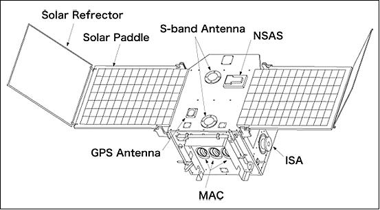
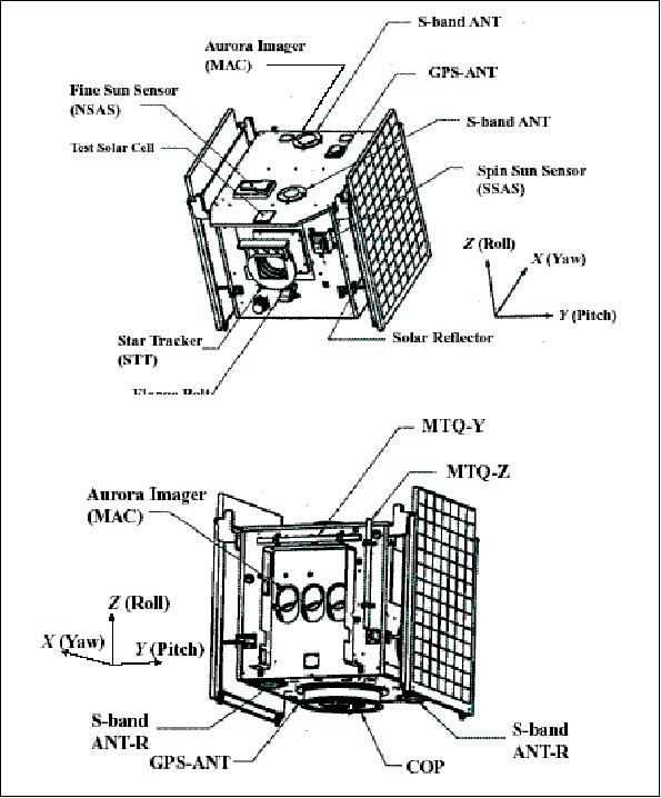
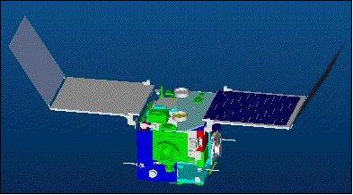
The S/C is three-axis stabilized, of cube geometry with an edge length of 50 cm, featuring two solar concentrator arrays (triple-junction solar cells) which are deployable as paddles (contractor: NEC Toshiba Space Systems, Tokyo). The maximum power generation is 160 W. In addition, a new type of lithium-ion battery is utilized with a total of 6.0 Ah of energy capacity. The satellite is oriented in a sun-pointing direction.
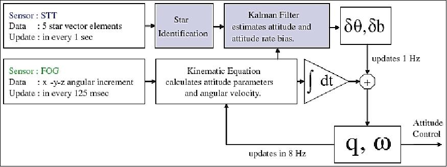
The S/C features a momentum-biased ACS (Attitude Control Subsystem). Attitude is sensed by SSS (Spin-type Sun Sensor), a 2-D sun sensor, a star tracker (STT), a three-axis geomagnetic aspect sensor, and a three-axis FOG (Fiber Optic Gyroscope) providing an overall pointing accuracy of 0.1º (the star tracker provides an accuracy of 0.05º within its operational range). The actuators used are: a small bias-momentum system (one momentum wheel, with 0.5 Nms momentum), and three-axis magnetic torquers (MTQs). The momentum wheel provides agility about the roll axis, and the MTQs generate an attitude control torque around yaw and pitch axis. Note: With only one momentum wheel in one axis and no thrusters, quick sun acquisition is impossible. Sun acquisition with slow rate is performed by magnetic torquers. 11) 12) 13) 14) 15)
STT has of FOV of 30º x 40º and outputs five star vectors coordinates with 3 arcmin (3σ) accuracy and magnitude of 0.1 (3σ) every second. The number of stars is limited less than 256 for each onboard star catalog (there are 4 star catalogs onboard).
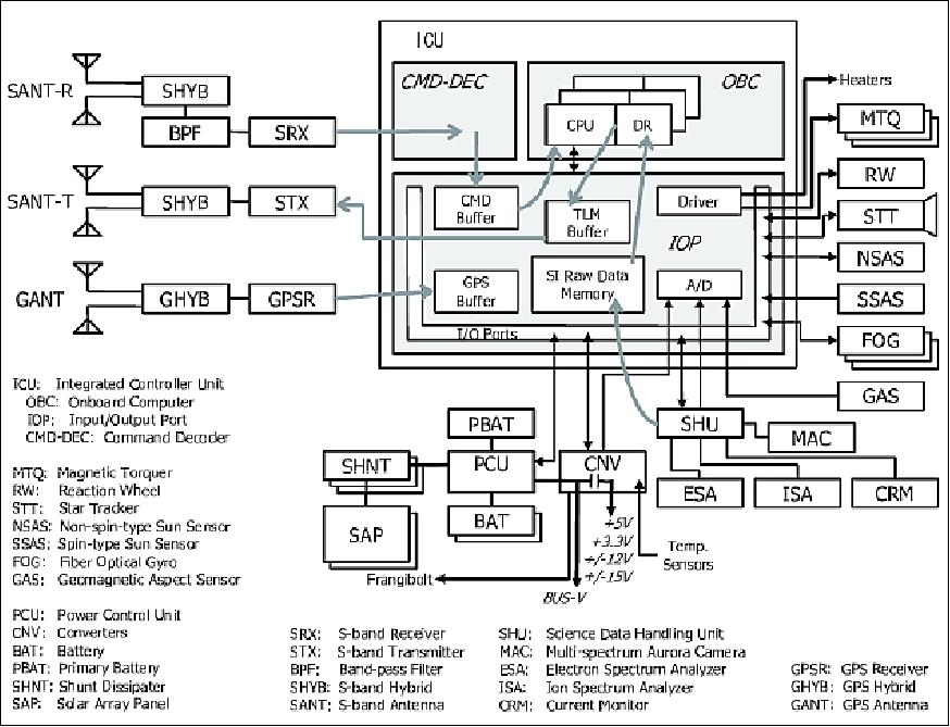
The S/C is controlled by the ICU (Integrated Control Unit), a fault-tolerant system (software), namely FDIR (Fault Detection and Recovery), which manages all peripheral equipment including the sensors and the actuators. Orbit determination is provided by an on-board GPS receiver and by Doppler measurements. INDEX tests the functions of a compact commercial GPS receiver as used for car navigation. The total S/C mass is 72 kg, including 10 kg of science payload mass. The nominal design life of the spacecraft is 3 months (with a goal of an extension).
Mission objective | Observation of fine structure of Aurora (Imager and Particle Analyzer) engineering technology demonstration (7 items) |
Spacecraft mass, size | 72 kg, 72 cm x 62 cm x 62 cm |
Spacecraft power | 160W, Solar-concentrated solar panels, 6.0 Ah lithium ion battery |
Attitude | Bias-momentum three-axis control, pointing accuracy of 0.05º |
Mission life | Minimum of 3 months |
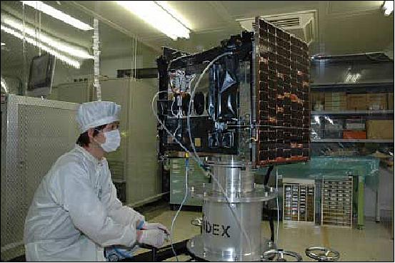
The design, development, integration and the test of INDEX/REIMEI spacecraft was done by JAXA/ISAS personnel. Common instruments such as battery and solar panels were built by satellite manufacturing companies. The data handling instruments and power management instruments were fabricated by small venture companies. Many young staff members and students were involved in the development of the spacecraft, working together with the venture companies- an effective environment for space education.
Momentum wheel | 1 |
Magnetic torquer (MTQ) | 3 |
Star tracker | 1 |
FOG (Fiber Optic Gyros) | 3 |
Sun sensor | 1 |
Magnetometer | 1 |
RF communications: An S-band system is used with non-coherent uplink and downlink. The data rates are: 1 kbit/s for the uplink and 131 kbit/s (max) for the downlink; the nominal downlink is 32 kbit/s. The main control station of INDEX/REIMEI is the newly developed JAXA/ISAS small satellite station with a 3 m antenna at the Sagamihara campus. 17)
Since INDEX/REIMEI does not have a two-way ranging function, orbit determination is based on one-way Doppler measurements by the domestic ground station network, while the onboard GPS receiver as a mission instrument can be used in addition. 18)
Launch
A launch of INDEX took place on Aug. 23, 2005 (UTC) as a secondary payload to OICETS on a Dnepr-1 launch vehicle from Baikonur, Kazakhstan.
Orbit: Sun-synchronous orbit, altitude = 608 km x 655 km, inclination = 98.16º, the local equator crossing time is at 0:50 hours and at 12:50 hours, period = 97.3 minutes.
Engineering Payload
The following advanced spacecraft technologies are being demonstrated and validated, intended to be used as "standard items" on future missions:
• Light design of a three-axis attitude control system
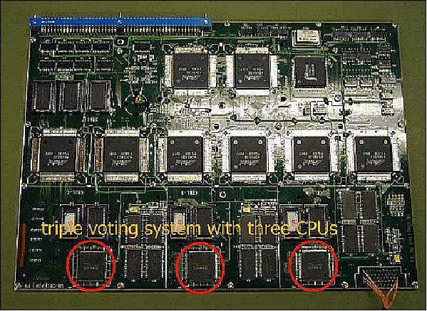
• An ICU (Integrated Control Unit) is introduced, a COTS (Commercial-Off-The-Shelf) based product, consisting of a high-speed 32 bit fault-tolerant RISC processor (SH-3, 60 MIPS, 0.5 W) with a three-voting system of SH-3, an embedded DRAM memory of 16 MByte with EDAC , a ROM system of 128 kByte with EDAC, and a user ROM of 384 kByte. The processor is not radiation hardened. SH-3 is expected to detect SEUs (Single Event Upsets).
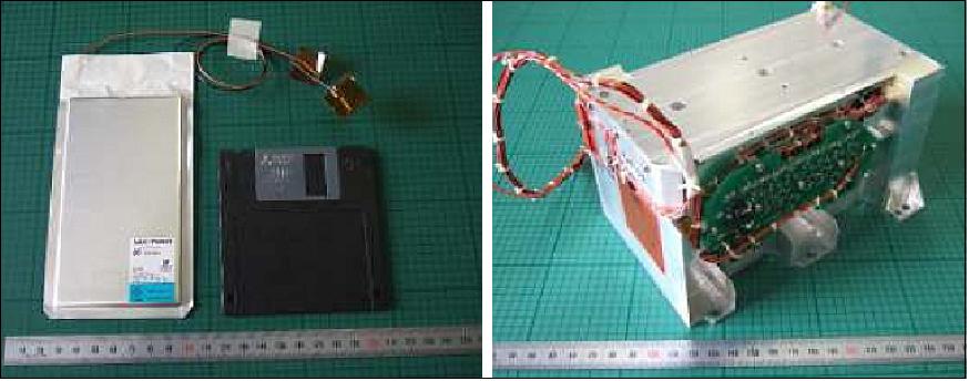
• A lithium-ion rechargeable battery with lithium manganate as main satellite battery. Use of off-the-shelf lithium-ion pouch cells in the battery (Figure 11).
Specification of 3Ah lithium-ion cell | Specification of the lithium-ion secondary battery | ||
Electrode | Positive: LiMn2O4 | Composition | 7 series of the cells |
Rated capacity | 3.0 Ah | Potting material | Epoxy resin |
Mass | 75 g | Case material | Aluminum |
Dimension | 145 mm x 80 mm x 4 mm | Dimension | 168 mm x 102 mm x 96 mm |
Energy density | 158 Wh/kg | Mass | 2.42 kg |
Charge voltage | 4.2 V / 4.1 V | Energy density | 70 Wh/kg |
• A newly developed solar concentrator array technology is employed on four paddles using a multi-junction cell design for the capture of a larger portion of the EMS (UV, VNIR and IR). The triple-junction cells provide a conversion efficiency of 26%. The concentrators are very light reflectors attached to the tips of two paddles at an angle of 60º. 19)
• Test of a new light-weight thermal louver device. A variable emittance radiator design makes use of perovskite material (La Ca MnO3). The material has metal-like properties at elevated temperatures and dielectric-like properties at low-level temperatures. The transition temperature is dependent on the material composition.
• The SOI (Silicon-On-Insulator) technology is being used by the SRAM (Static Random Access Memory) and ICU
• A compact small camera is flown utilizing the CMOS/APS (Active Pixel Sensor) detector technology
• A compact image-compression technique is introduced using the method of ball grid array packages
• A simple satellite operation concept is introduced with corresponding software on PC terminals.
Mission Status
• January 2017: The INDEX/REIMEI satellite and its payload are operational (12th year on orbit). 20)
• Sept. 28, 2015: The research groups of JAXA, Nagoya University and other related agencies clarified the structure of flickering aurora by analyzing the observation data of the JAXA satellite "REIMEI" (INDEX), combined with computer simulations conducted by Nagoya University. The research shows that a space electromagnetic wave called "Chorus" modulates electrons to create pulsating movement of the aurora. 21)
- The aurora is a phenomenon generated by a collision of electrons falling from space and the upper atmosphere at around 100 km in altitude. The aurora that is blinking every few seconds is called "pulsating aurora". It has a mysterious character of flickering a few times in a second. What causes this flickering has been unknown.
- The research this time clarifies the structure of the aurora flickering by modulating electrons that cause the aurora using space electromagnetic waves. The wave called "Chorus" sounds like birds' warbling when the electromagnetic wave is converted to sound. The research this time elucidated that this chorus causes blinking and flickering of pulsating aurora by the same mechanism.
• The INDEX/REIMEI spacecraft is operational in 2015 after 10 years on orbit. 22)
• The INDEX/REIMEI spacecraft continues to operate in 2013, however, with reduced observation capability. Some major events occurred in the meantime (Ref. 24):
- One gyro of the sensor assembly malfunctioned which resulted in a gyro-less attitude determination mode. As a consequence, a new control software was developed and uploaded to INDEX/REIMEI in 2011. Hence, the 3-axis attitude control function was successfully recovered. The new situation required the acceptance of some degradation in attitude control / knowledge accuracy.
- The scientific instrument ISA (Ion Spectrum Analyzer) malfunctioned in 2011. Since the ESA (Electron Spectrum Analyzer) instrument failed already prior to the ISA event, the entire ion and electron spectrum analyzer function was lost. The remaining MAC (Multi-spectral Auroral Camera) instrument is still operational.
• The INDEX/REIMEI spacecraft and its payload are operating nominally in 2011.
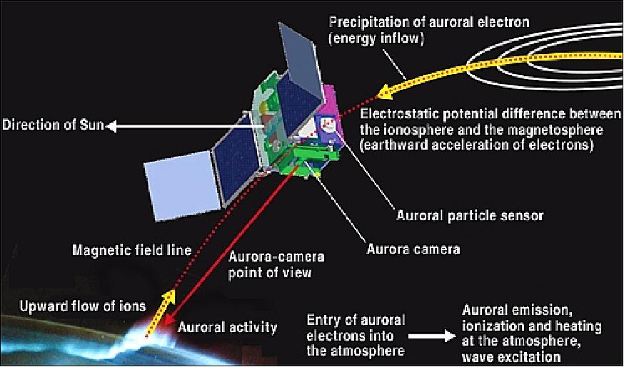
• The INDEX/REIMEI spacecraft and its payload are operating nominally in 2010 (completing its 5th year on orbit in August 2010, well beyond its design life of 3 months) - and still supporting several scientific observations almost every day. Three axis control of the spacecraft is achieved with an accuracy of 0.1º (3σ). The most advanced approach in the auroral observation by REIMEI is the simultaneous measurement of auroral emissions and particles using the satellite attitude control and the satellite orbit (Figure 7). 23) 24)
• In the fall of 2009, the IDEX/REIMEI Team received an award from the Tha Japan Society of Aeronautical and Space Science for outstanding technical achievements of the mission (Ref. 24).
• Initial on-orbit operations started by the end of October 2005. All mission objectives were verified/supported within the first 3 months.
• Collaborative observations of INDEX/REIMEI were conducted in several coordinated campaigns with ground observation networks: EISCAT (European Incoherent Scatter Radar), all-sky cameras, and SuperDARN (Super Dual Auroral Radar Network). The last all-sky camera and REIMEI campaign (simultaneous observations) over Iceland was in late 2006. 25) 26)
Sensor Complement
The primary science objectives of INDEX call for observations of auroral emissions, particles, and the plasma environment with high time and spatial resolutions - for clarifying the fine-scale structures of the auroral acceleration region and their relationship to precipitating particles. 27)
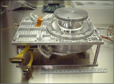
EISA (Electron/Ion Spectrum Analyzer)
EISA is also referred to as ESA/ISA. The objective is the investigation of formation mechanisms of aurora1 fine-scale structures. The measurement technique obtains simultaneously pitch-angle distributions of aurora1 particles and optical images of auroral arcs emitting in the ionospheric footprint region. The measurements require a high time resolution which in turn implies high count rates. 28)
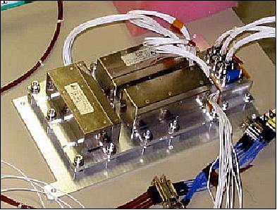
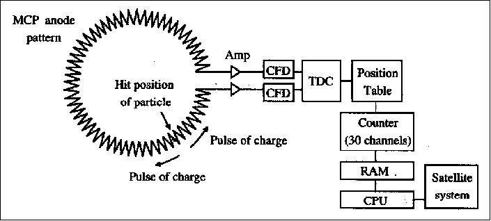
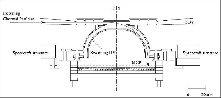
EISA is an electrostatic analyzer consisting of ESA (Electron Spectrum Analyzer) and ISA (Ion Spectrum Analyzer). For high time resolutions, energy steps of the instruments are divided in two groups. For each sensor, there are 32 different energy steps whose energies are exponentially defined. A delay line anode technique is used for EISA to measure the signal propagation time of the anode pattern (Figure 12).
Whenever a particle hits the MCP (Microchannel Plate) detector, a pulse of charge arrives at an anode, and is divided into two groups. Each of them propagates to the end of the anode pattern where a TDC (time-to-digital convertor) is installed. Then a time interval between arrival timings of the two pulses is measured by the TDC. From this interval, the hit positions of incoming particles can be deduced. The minimum angular resolution of the readout system of the EISA is 5º, which is mainly determined by time resolution characteristics of the TDC. EISA can handle up to 2 x 10⁶ counts/s.
Particle species | ESA electrons, ISA: ions (no mass resolution) |
Energy range | ESA: 12 eV-12 keV, ISA: 10 eV/ q-12 keV/q |
Energy resolution (delta E/E) | 15% FWHM (Full Width Half Maximum) |
Energy steps | 32 |
FOV (Field of View) | 4º x 300º |
Angular resolution | 30 bins in polar angle direction |
Time resolution | 20 ms / 16 energy steps (40 ms / 32 energy steps); the time resolution of 20 ms is equivalent to spatial resolution of about 150 m |
Geometrical factor | ESA: 2.8 x 10⁻⁴ [cm2 str eV/eV/10º] (10º: polar angle direction) |
Instrument mass | 1.4 kg/sensor head (including HVPS and preamplifier) |
Instrument power | 2.5 W/sensor head |
Data rate | 205 kbit/s for each sensor (uncompressed case) |
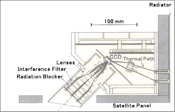
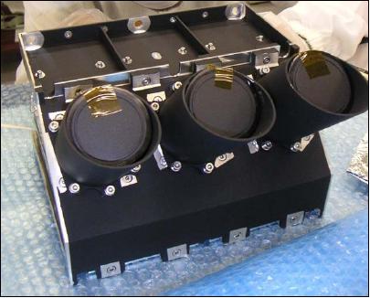
MAC (Multichannel Auroral Camera)
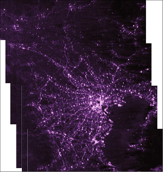
MAC is a multispectral camera with the objective to make auroral imaging observations with high time and spatial resolutions at three different wavelengths. MAC has three channels, each channel has an interference filter, objective lenses, and a CCD chip which is cooled by a thermal path using graphite sheets connected to a radiator. MAC also includes the electric boards to conduct digital and analog data processing and to provide clock signals for the CCD. The data is quantized at 12 bit. 29)
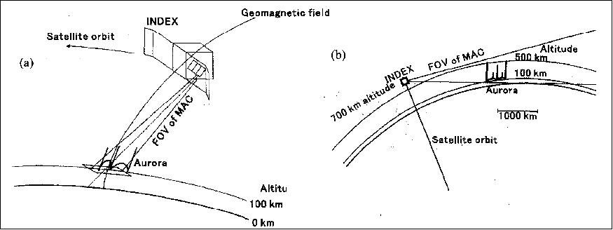
MAC is installed on the satellite in such a way that the direction of field-of-view (FOV) is 45º slanted with respect to the surface of satellite panel. This slant angle is selected to observe the auroral emissions at the magnetic foot point in the nightside aurora1 oval.
Apparatus item | Parameter and value | ||
Radiation blocker | Material: synthetic silica, diameter: 50 mm, thickness: 10 mm | ||
Interference filters | Center frequency (nm) | FWHM (nm) | Peak transmittance |
- N2+ first negative | 428.2 | 2.47 | 0.46 |
Objective lenses | Material: fused silica, f=50 mm, F=2.0, FOV = 7.6º | ||
CCD | Type: interline, pixels: 1024 x 1024, pixel size: 6.45 µm x 6.45 µm | ||
Cooling of CCD | Thermal path using graphite sheets connected to the radiator. The CCD is cooled to -10ºC | ||
Instrument mass | 4.5 kg | ||
Instrument power | 11 W (1 channel on), 13 W (2 channels on), 15 W (3 channels on) | ||

CRM (Plasma Current Monitor)
CRM measures plasma density and temperature with a sampling rate of 200 Hz.
Observation modes of MAC and EISA
1) The MAC instrument offers two observation modes:
a) Mode-S (simultaneous measurement mode) for image and particle observations.
b) Mode-H refers to the aurora1 height distribution measurement mode.
In both modes, a 16 x 16 pixel binning of CCD is performed taking a compromise among fast exposure time, sufficient sensitivity for weak aurora1 intensity, satellite motion during an exposure, data processing speed, and capacity of the satellite system memory into account. The CCD area is is divided into 64 x 64 bins.
Parameter | Spatial resolution | Area size per image | Exposure cycle |
Mode-S | 1.2 km x 1.2 km at 100 km altitude | 80 km x 80 km at 100 km altitude | 120 ms exposure, 40 ms, pause 80 ms |
Mode-H | 4 km x 4 km at 2000 km distance from the S/C | 270 km x 270 km st 2000 km distance from the S/C | 1 s (exposure: 480 ms, pause 520 ms |
2) The EISA instrument exhibits two observation modes:
a) Mode-T (field-line tracking mode for particle observations). During the auroral particle measurements in this mode, satellite attitude is controlled by the reaction wheel system - keeping the geomagnetic field orientation within the FOV of EISA, so that particle distributions with full pitch-angle coverage can be obtained with a time resolution determined only by a period of internal energy scan (20 ms). The time resolution of 20 ms is equivalent to spatial resolution of about 150 m, since the satellite velocity is about 7.5 km/s. Note: The MAC instrument is turned off in the Mode-T.
In this mode, a data set of aurora1 particles is obtained at the pre-midnight region regardless of the season, since the INDEX satellite is on the sun-synchronous orbit, namely almost on the same meridian (10:30 - 22:30 local time).
b) Mode-S (simultaneous measurements of auroral images and particles). Mode-S is the most important one in the mission (see Figure 20).
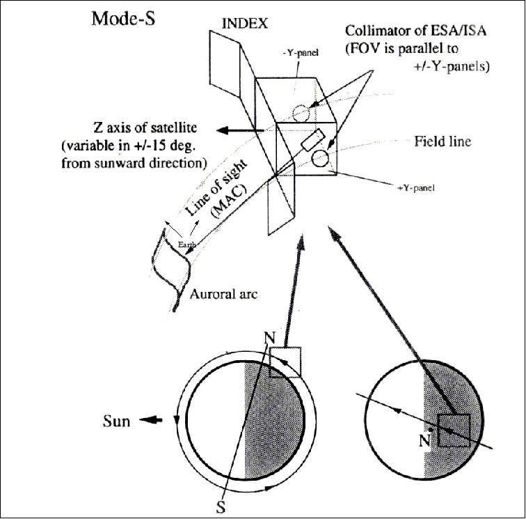
In Mode-S, the z-axis of the satellite has to be within 15º from the sunward direction due to power limitations (sufficient generation capability). The S/C attitude is controlled so that the FOV of MAC includes an ionospheric footprint of the geomagnetic field, which passes through the satellite. At the same time, distributions of auroral particles are measured by the EISA instrument. Simultaneous observations of fine-scale images of auroral arc emissions and corresponding auroral particle distributions with full pitch-angle coverage can be made, whenever EISA can measure field-aligned directions in this mode. This situation is expected to occur most likely during the winter season in the northern hemisphere.
References
1) http://www.jaxa.jp/projects/sat/index/index_e.html
2) T. Mizuno, H. Saito, Y. Masumoto, T. Oshima, et al., "INDEX: A Piggy-Back Satellite for Advanced Technology Demonstration," Proceedings of the 13th AIAA/USU Conference on Small Satellites, Aug. 23-26, 1999, SSC99-IX-4
3) S. Sakai, Y. Fukushima, H. Saito, "Attitude Controller Design for Small Satellite Taking Account of Gyro Sensor Noise," Proceedings of IAC 2004, Vancouver, Canada, Oct. 4-8, 2004,
4) Information provided by Shin-ichiro Sakai of JAXA/ISAS
5) H. Saito, T. Mizuno, K. Tanaka, Y. Sone, S. Fukuda, S. Sakai, N. Okuizumi, M. Mita, Y. Fukushima, M. Hirahara, K. Asamura, T. Sakanoi, A. Miura, T. Ikenaga, Y. Masumoto, "An Overview and Initial In-Orbit Status of INDEX Satellite," Proceedings of 25th ISTS (International Symposium on Space Technology and Science) and 19th ISSFD (International Symposium on Space Flight Dynamics), Kanazawa, Japan, June 4-11, 2006, paper: 2006-keynote-04v
6) Shin-ichiro Sakai, Yosuke Fukushima, Hirobumi Saito, "Design and On-Orbit Evaluation of Attitude Control System for Small Scientific Satellite REIMEI," Proceedings of 25th ISTS (International Symposium on Space Technology and Science) and 19th ISSFD (International Symposium on Space Flight Dynamics), Kanazawa, Japan, June 4-11, 2006, Paper: 2006-d-84
7) H. Saito, T. Mizuno, K. Tanaka, Y. Sone, S. Fukuda, S.-I. Sakai, N. Okuizumi, M. Mita, Y. Fukushima, M. Hirahara, K. Asamura, T. Sakanoi, A. Miura, T. Ikenaga, Y. Masumoto, "An Overview and Initial In-Orbit Status of INDEX Satellite," Proceedings of the 20th Annual AIAA/USU Conference on Small Satellites, Logan, UT, Aug. 14-17, 2006, paper: SSC06-IV-1, URL: http://digitalcommons.usu.edu/cgi/viewcontent.cgi?article=1552&context=smallsat
8) Y. Fukushima, S.-I. Sakai, H. Saito, "Flight performance of the REIMEI microsatellite attitude determination system," Proceedings of the 4S Symposium: `Small Satellite Systems and Services,' Chia Laguna Sardinia, Italy, Sept. 25-29, 2006, ESA SP-618
9) Yoshitusugu Sone, Masatoshi Uno, Yasuo Takeda, Koji Tanaka, Hirobumi Saito, Michio Tajima, "The Flight and Ground Test Data of the Lithium-Ion Secondary Battery of REIMEI," Proceedings of 25th ISTS (International Symposium on Space Technology and Science) and 19th ISSFD (International Symposium on Space Flight Dynamics), Kanazawa, Japan, June 4-11, 2006, paper: 2006-f-04
10) H. Saito, T. Mizuno, K. Tanaka, Y. Sone, S. Fukuda, Shin-ichiro Sakai. N. Okuizumi, M. Mita, Y. Fukushima, M. Uno, Y. Yanagawa, T. Takahara, R. Kaneda, T. Honma, M. Hirahara, K. Asamura, T. Sakanoi, A. Miura, T. Ikenaga,H. Nagamatsu, K. Ogawa, Y. Masumoto, "An overview and lessons-learned of small scientific satellite "INDEX" (REIMEI)," 58th IAC (International Astronautical Congress), International Space Expo, Hyderabad, India, Sept. 24-28, 2007, IAC-07-B4.4.05
11) S. Sakai, Y. Fukushima, R. Kaneda, H. Saito, "Studies on Magnetic Attitude Control System for the REIMEI Microsatellite," Proceedings of the AIAA Guidance, Navigation, and Control Conference, AIAA 2006-6450, Keystone, CO, USA, Aug. 21-24,2006
12) S. Fukuda, S. Sakai, Y. Fukushima, K. Asamura, T. Takahara, R. Kaneda, Yo. Yanagawa, T. Mizuno, H. Saito, "Flexible Operation System for the Microsatellite `REIMEI' (INDEX)," Proceedings of SpaceOps2006, Rome, Italy, June 19-21, 2006
13) Shin-ichiro Sakai, Yosuke Fukushima, Hirobumi Saito, "Design and on-orbit evaluation of magnetic attitude control system for the REIMEI microsatellite," Proceedings of the 6th IAA Symposium on Small Satellites for Earth Observation, Berlin, Germany, IAA-B6-0503 April 23-26, 2007
14) http://www.isas.jaxa.jp/e/forefront/2004/saito_hukuda/02.shtml
15) Shin-ichiro Sakai, Yosuke Fukushima, Hirobumi Saito, "Design And On-Orbit Evaluation Of Magnetic Attitude Control System For The `REIMEI' Microsatellite," Proceedings of the 10th International Workshop on Advanced Motion Control (AMC), Trento, Italy, March 26-28, 2008
16) Shin-ichiro Sakai, Yosuke Fukushima, Aritaka Ohno, Hirobumi Saito, "In-orbit Performance Evaluation of Temperature Controlled Small Fiber Optical Gyro on Microsatellite REIMEI," Proceedings of the 18th International Conference on Optical Fiber Sensors, Cancun, Mexico, Oct. 23-27, 2006.
17) S. Fukuda, T. Mizuno, S. Sakai, Y. Fukushima, K. Asamura, T. Homma, T. Takahara, R. Kaneda, Y. Yanagawa, H. Saito, "On-Orbit Performance of the REIMEI Satellite with Integrated Computer System and Introduction to Its Flexible Operation," Proceedings of 25th ISTS (International Symposium on Space Technology and Science) and 19th ISSFD (International Symposium on Space Flight Dynamics), Kanazawa, Japan, June 4-11, 2006, paper: 2006-f-01
18) H. Saito, Y. Hamada, T. Mizuno, H. Sasaki, T. Saiki, "Development and On-orbit Results of Miniature Space GPS Receiver by means of Automobile-Navigation Technology," Proceedings of 25th ISTS (International Symposium on Space Technology and Science) and 19th ISSFD (International Symposium on Space Flight Dynamics), Kanazawa, Japan, June 4-11, 2006, paper: 2006-f-02
19) Nobukatsu Okuizumi, Hirobumi Saito, Koji Tanaka, Ken Higuchi, "Wrinkling and Reflection Characteristics of Membrane Solar Reflectors of REIMEI Spacecraft," Proceedings of 25th ISTS (International Symposium on Space Technology and Science) and 19th ISSFD (International Symposium on Space Flight Dynamics), Kanazawa, Japan, June 4-11, 2006, paper: 2006-c-14
20) http://global.jaxa.jp/projects/
21) "Mystery of Flickering Aurora: Elucidate the Structure of Pulsating Aurora by "REIMEI" Observations with Computer Simulation," JAXA, Sept. 28, 2015, URL: http://global.jaxa.jp/press/2015/09/20150928_reimei.html
22) Catalog of ISAS Missions, URL: http://www.isas.jaxa.jp/e/enterp/missions/catalogue.shtml
23) Hirobumi Saito, M.Hirahara, T. Mizuno, S. Fukuda, S. Sakai, Y. Fukushima, K. Asamura, H. Nagamatsu, "Small Satellite REIMEI for Auroral Observations," Proceedings of the 61st IAC (International Astronautical Congress), Prague, Czech Republic, Sept. 27-Oct. 1, 2010, IAC-10.B4.2.3
24) Information provided by Shin-ichiro Sakai of JAXA/ISAS
25) M. Hirahara, T. Sakanoi, K. Asamura, Y. Obuchi, T. Ino, A. Yamazaki, Y. Kasaba, Y. Ogawa, S. Nozawa, K. Seki, "Observations of fine structure and variation of auroral emissions and particles with high-time and spatial resolutions: Initial results of the Reimei satellite and simultaneous ground-based observations," Geophysical Research Abstracts, Vol. 8, 04915, 2006; SRef-ID: 1607-7962/gra/EGU06-A-04915, URL: http://www.cosis.net/abstracts/EGU06/04915/EGU06-J-04915.pdf
26) http://www.isas.jaxa.jp/e/forefront/2006/hirahara/03.shtml
27) Masafumi Hirahara, Yukinaga Miyashita, Yusuke Ebihara, Kanako Seki, "Introduction of Plasma Particle Data Analysis for Reimei Observations," URL: https://web.archive.org/web/20161222025705/http://www.iugonet.org/meetings/2010-02-25/05_Reimei_EISA_Hirahara_20100225.pdf
28) K. Asamura, D. Tsujita, H. Tanaka, Y. Saito, T. Mukai, M. Hirahara, "Auroral Particle Instrument onboard the INDEX Satellite," Advances in Space Research, Vol. 32, No. 3, pp. 375-378, .2003
29) T. Sakanoi, S. Okano, Y. Obuchi, T. Kobayashi, M. Ejiri, K. Asamura, M. Hirahara, "Development of the Multispectral Camera onboard the INDEX Satellite," Advances in Space Research, Vol. 32, No. 3, pp. 379-384, .2003
30) https://web.archive.org/web/20120903134116/http://www.isas.ac.jp:80/e/forefront/2006/hirahara/index.shtml
The information compiled and edited in this article was provided by Herbert J. Kramer from his documentation of: "Observation of the Earth and Its Environment: Survey of Missions and Sensors" (Springer Verlag) as well as many other sources after the publication of the 4th edition in 2002. - Comments and corrections to this article are always welcome for further updates (eoportal@symbios.space).
Spacecraft Launch Mission Status Sensor Complement References Back to top