IceCube (Earth-1)
EO
NASA
GSFC
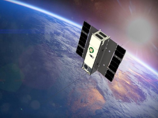
IceCube was a cloud ice observation 3U CubeSat nanosatellite operated by NASA (National Aeronautics and Space Administration) and GSFC (Goddard Space Flight Centre), and managed and co-funded by ESTO (Earth Science Technology Office). Its objective was to validate a new 874 GHz submillimeter wave radiometer for cloud ice observation, and it continued operations after this test due to the usable data it was obtaining. IceCube acquired the first 883 GHz cloud map from cloud-induced scattering radiance. The satellite was launched on 18 April 2017 and deployed from the ISS on 16 May 2017.
Quick facts
Overview
| Mission type | EO |
| Agency | NASA, GSFC |
| Launch date | 18 Apr 2017 |
Summary
Mission Capabilities
The principal instrument on board IceCube was the ICIR (IceCube Cloud-Ice Radiometer). This consisted of an RF (Radio Frequency) receiver comprised of an offset parabolic reflector with feedhorn, mixer, stable oscillator, RF multiplier chain, IF (Intermediate Frequency) chain, video amplifier, and detector. Also present were supporting circuit boards including the iPDU (Instrument Power Distribution Unit) and C&DH (Command and Data Handling). Through these systems, the ICIR was capable of providing an accurate assessment of the distribution of atmospheric ice.
Performance Specifications
At nadir, ICIR’s main beam covered a 3 dB footprint of 10 – 20 km for an orbital altitude in the range of 400 – 800 km, respectively. The ground track velocity of the spacecraft was approximately 7 km/s, and its period of orbit was approximately 1.55 hours.
IceCube followed a near circular orbit at an altitude of approximately 400 km and an inclination of 51.6°.
Space and Hardware Components
The spacecraft bus of IceCube was a 3U customised CubeSat. The EPS (Electrical Power Subsystem) consisted of two 3U double deployable solar arrays - which produced 30 W at BOL (Beginning of Life) - and a 2U body-mounted array for power generation. A 40 Wh battery was used during eclipse operations. GNC (Guidance, Navigation, and Control) consisted of the XACT ADCS (Attitude Determination and Control Subsystem) and the Novatel OEM615 GPS (Global Positioning System) receiver. The XACT ADCS consisted of an ST (Star Tracker), two axis sun sensor, MEMS IMU (Inertial Measurement Unit), three reaction wheels, three magnetic torquer rods, and a processor for control. The GPS receiver was used for position and velocity determination. Finally, IceCube employed a two-zoned passive thermal control system (excluding the heaters).
IceCube — 874 GHz submillimeter wave radiometer mission on a 3U CubeSat
IceCube Radiometer Spacecraft Launch Mission Status Ground Segment References
IceCube is a NASA/GSFC (Goddard Space Flight Center) nanosatellite mission with the objective to validate a new 874 GHz submillimeter wave radiometer for cloud ice observations. The measurements of ice clouds and their processes are important for climate models and for cloud precipitation processes.
- In July 2014, NASA's SMD (Science Mission Directorate) selected a team at GSFC, led by PI Dong L. Wu, to build its first Earth science-related CubeSat mission. The IceCube project is being managed and co-funded by the ESTO (Earth Science Technology Office) of NASA. 1) 2) 3) 4)
Background:
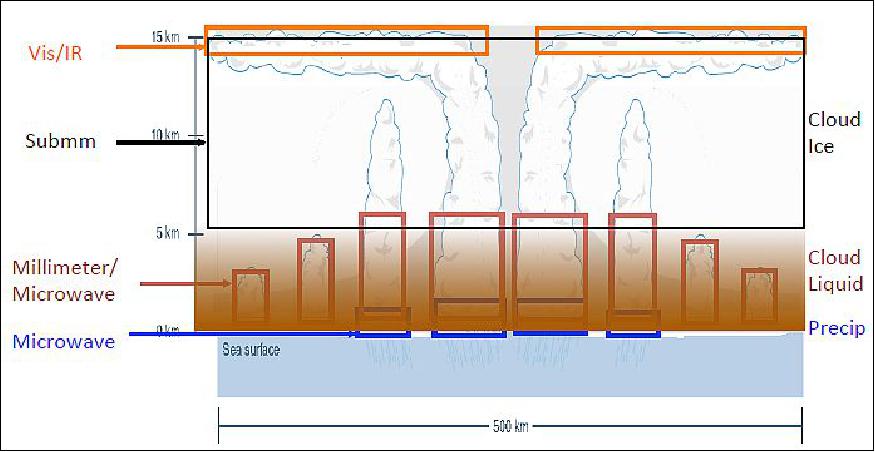
Ice clouds play a key role in Earth's climate system, primarily through regulating atmospheric radiation and interacting with dynamic, energetic and precipitation processes. Sub-millimetre wave remote sensing offers a unique capability for improving cloud ice measurements from space, due to its great depth of cloud penetration and volumetric sensitivity to cloud ice mass.
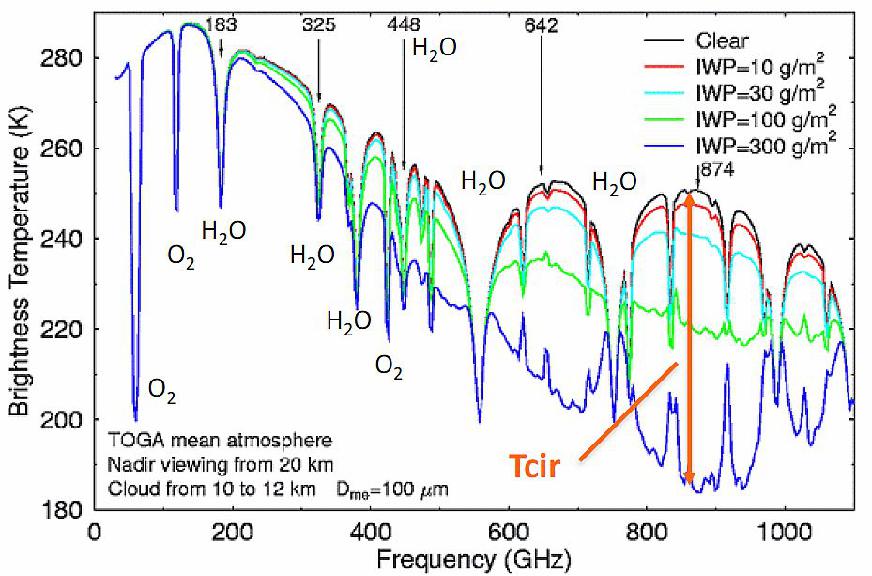
At 874 GHz, ice cloud scattering produces a larger brightness temperature depression than at lower frequencies, which can be used to retrieve vertically-integrated cloud IWP (Ice Water Path) and ice particle size. This effect was measured with the CoSSIR (Compact Scanning Sub millimetre wave Imaging Radiometer), an airborne instrument developed at NASA/GSFC.
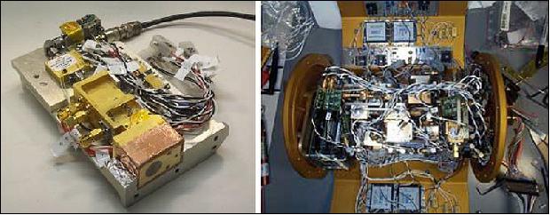
- CoSSIR is a conical and cross-track imager with six receivers and eleven channels centred at 183, 220, 380, 640 V&H, and 874 GHz (Figure 1).
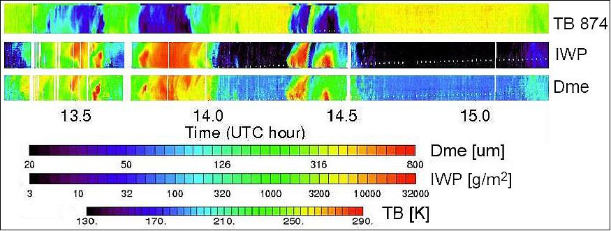
- CoSSIR measurements from NASA's ER-2 aircraft showed that the selected channel set is capable of accurately retrieving IWP in a wide dynamic range between ~10 g/m2 and 10,000 g/m2 after validation against cloud radar and lidar, with large brightness temperature depression centred at 874 GHz (Figure 2).
The objective of the IceCube project is to retire risks of the 874 GHz receiver technology for future Earth and space remote sensing instruments by raising its TRL (Technology Readiness Level) from 5 to 7. The project will demonstrate, on a 3U CubeSat in a LEO (Low Earth Orbit) environment, a receiver system with a NEDT (Noise Equivalent Differential Temperature) of ~0.15 K over 1-second integration, and <2 K calibration uncertainty.
IceCube is scheduled for launch and subsequent release from the ISS (International Space Station) in mid-2016 for a nominal operation of 28+ days. In addition to its technology demonstration, IceCube will acquire the first 874 GHz cloud map from cloud-induced scattering radiance, thereby accelerating scientific exploration through efficient and frequent access to space using CubeSats. The receiver technology used here was initially developed by VDI (Virginia Diodes Inc.), under NASA's SBIR Phase II program. Communication with the CubeSat will be through NASA's WFF (Wallops Flight Facility) UHF station. Mission Operations and data processing and validation will be conducted at GSFC.
The new 874 GHz radiometer of IceCube is based on a previous design for the airborne instrument CoSSIR ( Compact Scanning Submillimeter-wave Imaging Radiometer), a 12 channel (183 - 874 GHz) total power imaging radiometer that was mainly developed for the measurements of ice clouds.
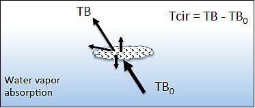
Ice cloud scattering at sub-mm waves:
• Higher sensitivity to cloud scattering at sub-mm waves
• Cloud-induced radiance, Tcir, is proportional to CIWP (Cloud Ice Water Path)
• Cloud microphysical properties (i.e., particle size) from different frequencies
• Simultaneous retrievals with T, H2O.
ICIR (IceCube Cloud–Ice Radiometer)
The key performance parameters of the IceCube radiometer are shown in Table 1.
The RF (Radio Frequency) receiver is comprised of an offset parabola reflector with feedhorn, mixer, stable oscillator, RF multiplier chain, IF (Intermediate Frequency) chain, video amplifier, and detector.
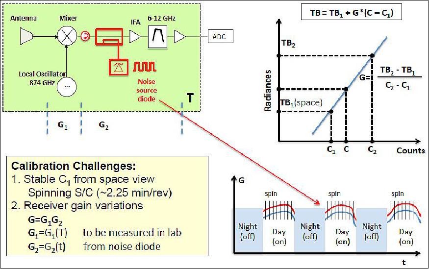
There are also supporting circuit boards including the iPDU (instrument Power Distribution Unit) and C&DH (Command and Data Handling), which are shared with the spacecraft. The radiometer will have a noise figure of 15 dB with an NEDT of ~0.15 K for a 1-second dwell time. The instrument is both externally and internally calibrated using views of deep space and an internal IF noise source and reference state. 5)
Parameter | Functional requirement |
Frequency band | 862-886 GHz with fc at 874 GHz |
Input RF channel | V polarization |
NEDT (Noise Equivalent Differential Temperature) | 0.15 K |
Calibration sources | Noise Diode/Reference Load (internal) |
IF (Intermediate Frequency) band | 6-12 GHz |
IF gain | 50-55 dB |
A/D Sampling | 10 kHz |
Integration time | 1 s |
Instrument mass, power | ≤ 1 kg, 11.2 W including 30% contingency |
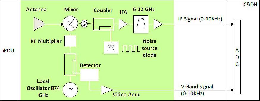
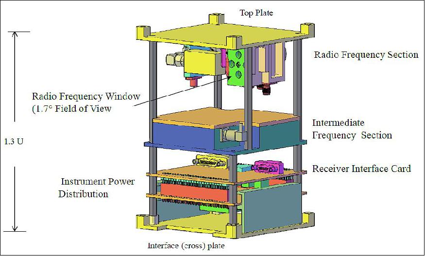
The radiometer simplified block diagram is shown in Figure 6 and the instrument layout is illustrated in Figure 7. The radiometer front-end is comprised of an 874 GHz LO (Local Oscillator). Intermediate frequency (6-12 GHz) calibration by noise injection provides the means of discriminating the calibration state of front-end components, referenced to extended observations of space. The RF input to the mixer is a GSFC-designed antenna, which is a straightforward offset-fed paraboloid yielding a 1.7º half-power beam width. At the nadir, the main beam will cover a ~10 to 20 km 3 dB footprint for an orbital altitude in the range of 400-800 km, respectively. With a ground track velocity of approximately 7 km/s, a 1-second output sampling period will provide 0.7 to 1.4 times the Nyquist sampling rate of the antenna main beam.
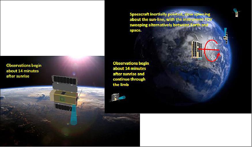
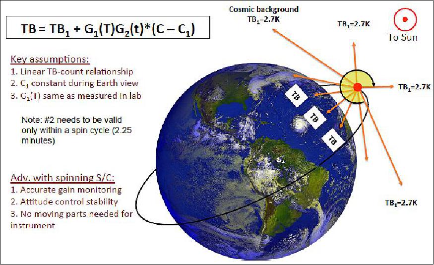
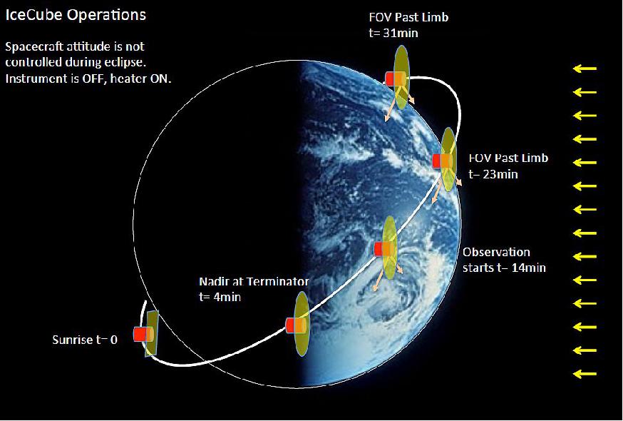
Calibration of the radiometer is achieved by both internal electronic and external natural target means. Externally, the primary target is space, which is viewable by pointing the antenna beam above the Earth's limb and providing the absolute offset of the system. Internal calibration of the receiver is carried out by the IF stage, which is used during and between external views of space. The noise source coupled into the IF path is used to estimate IF section gain. An illustration of the vehicle observations over an orbit is shown in Figure 8.
Mission Requirements
• In-flight operation 28 days
• Periodical views of Earth (science) and space (calibration) within an orbit
• Science data 30+% (8+h /day)
• Pointing knowledge < 25 km.
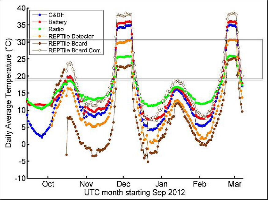
IceCube challenge No 2: Large orbital thermal variations
Constraints:
- Preferred instrument operations temperatures: 20-30ºC
- Low CubeSat/instrument mass, or thermal inertia, for thermal stability
- Wide range of β-angles: ±75°
- Day-on and night-off operations
- Spin around the Sun-pointing axis.
The IceCube mission is to demonstrate and space-qualify a commercially available 874 GHz submillimeter-wave receiver developed by VDI (Virginia Diodes Inc.), of Charlottesville, Virginia. This instrument is capable of providing an accurate assessment of the distribution of atmospheric ice.
Spacecraft
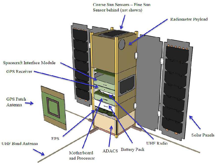
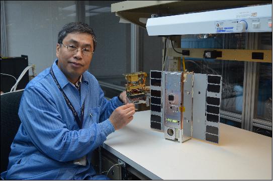
The 1.3U instrument is accommodated within a 3U CubeSat, with internal volume and mass margins adequate to fit within the required CubeSat specifications standards (CubeSat Design Specification Rev. 12, Cal Poly SLO). The CubeSat bus uses COTS components with proven flight heritage (Figure 12). The ADCS (Attitude Determination and Control Subsystem) and UHF antenna are attached to the end opposite the radiometer.
The overall system length is 340.5 mm, including 6.5 mm posts on both ends, with a 100 mm by 100 mm body frame. The mass of the nanosatellite is ~4 kg.
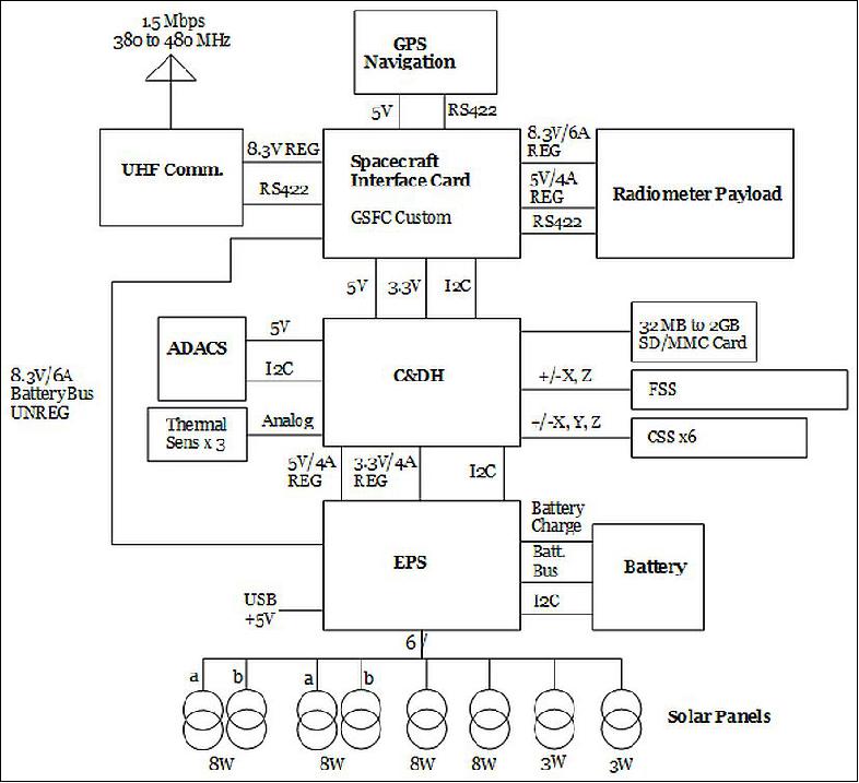
IceCube is a 3U customized CubeSat based on the model built by Pumpkin Inc. (with solar panels and batteries from Clyde Space and ADCS and GPS from Blue Canyon). Only one bus system card will be custom manufactured at GSFC and is necessary to provide a data interface to the instrument and other bus components. The electrical block diagram is shown in Figure 13.
Structure and Mechanisms:
The primary structure of the spacecraft is comprised of custom-machined aluminium walls, cross plates, and closeout panels. The bus electronics stack uses a threaded rod and spacer combination to tie the various printed circuit boards together. Interface brackets are used to join the science payload to the spacecraft bus. Mechanisms include two double deployable solar arrays and a deployable Ultra-High Frequency (UHF) antenna with two elements. Detailed assembly procedures helped guide the integration process and the system went together mechanically without any significant issues (Ref. 15).
Thermal Design:
IceCube implements a passive thermal control system (except for heaters). The instrument is power-cycled to keep it from running too warm, and the spacecraft makes use of operational heaters on the battery pack since it has the tightest temperature limits of all components.
The spacecraft has two thermal control zones:
1) the first zone consists of the bus plus the instrument electronics,
2) the second zone consists of the Mixer LO Assembly (MLA) / Intermediate Frequency Assembly (IFA) part of the instrument.
The MLA/IFA zone is isolated from the rest of the spacecraft with the use of ULTEM™ spacers and low emissivity coatings such as iridite and gold plating. The MLA/IFA components are thermally coupled to dedicated radiators that use a tailorable emittance coating to reject heat to space.
The spacecraft uses the +Y panel coated with Composite Coating Silver (CCAg), and the uncoated solar array mounting panels as radiators.
Electrical Systems:
The electrical system on IceCube consists of:
1) power,
2) C&DH,
3) communications,
4) attitude control subsystems.
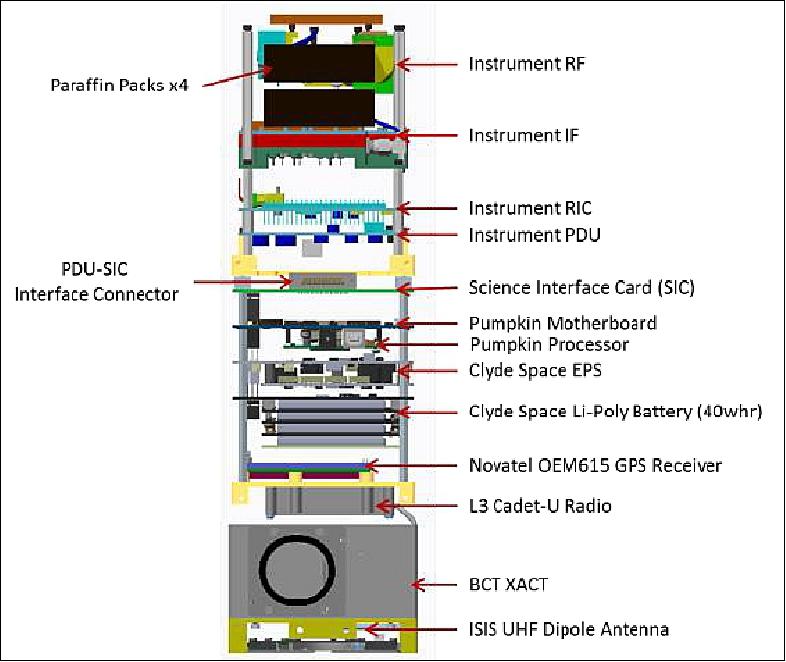
All spacecraft bus subsystem components are COTS with the exception of the Science Interface Card (SIC), which is a GSFC-designed card that provides level translation, analogue-to-digital conversion for the instrument health sensors, and an interface to the instrument radiometer digital counts. Figure 14 shows the general layout of the electrical system components.
The SIC, Pumpkin flight computer, and Clyde Space EPS (Electrical Power Subsystem) and battery are all mated via the CubeSat Kit Bus 100-pin header interface for passing nonregulated and regulated voltages, as well as data and clock signals. Due to some inconsistent bus pin use with the COTS components discovered during a detailed ICD document review, some pins had to be removed to avoid routing a voltage source from one card to a signal on another card.
A custom interface harness was constructed to mate to the CubeSat Kit Bus interface to allow power and data connection to:
1) the Cadet-U,
2) GPS receiver,
3) BCT (Blue Canyon Technologies) XACT (Attitude Determination & Control System Technology) ACS unit,
4) UHF antenna.
Additional connections requiring custom cables include those between the SIC and the instrument components, solar panels and battery, and power inhibits and battery.
Three mechanical switches (deployment switches) with connection to the battery were mounted to the longitudinal rail of the spacecraft, such that when installed in the deployer, the switches would be closed and prevent power delivery from the battery to the spacecraft components (referred to as power inhibits).
An external umbilical interface was accommodated in the mechanical layout to be used during I&T and ground testing. The umbilical interface allowed access to the release switch (deployment switch) inputs by bypassing the mechanical switches. The interface also provided external spacecraft power input and battery charge, a data interface to the flight computer, as well as coaxial disconnects for the GPS and UHF links which allowed for bypass of the antennas to provide direct access to the GPS receiver and Cadet-U.
EPS (Electrical Power Subsystem):
The IceCube power subsystem consists of two 3U double deployable solar arrays and a 2U body-mounted array for power generation. A 40 Wh battery is used during eclipse operations.
The electrical power subsystem is responsible for:
1) performing required voltage conversions,
2) charging the batteries,
3) completing power switching activities,
4) health monitoring for anomaly discovery and diagnosis.
Eclipses last 37 minutes maximum out of a 93-minute orbit. The 1U communications antenna has a built-in solar panel which does not regularly see the sun and is not normally required, except for detecting the sun during a contingency. The battery charge regulators of the EPS condition the power generated from the arrays into suitable levels for battery charge and subsystem feed.
Subsystem | Component | Power (W) |
Instrument | Power distribution, Interface Card, Instrument | 6 |
GNC/C&DH | GPS | 1.2 |
RF communications | Transmitter | 12.0 |
Power | EPS | 0.4 |
TCS (Thermal Control Subsystem) | Battery Heater | 0.8 |
Total |
| 24.0 |
Note: During data downlink times the science instrument is switched off, and the transmitter is switched on for about 9 minutes (max.). | ||
For an orbit period of about 1.55 hours and an eclipse of 0.62 hours, the battery stored energy requirement is about 15 Wh. Hence a 40 Wh. battery provides more than twice the needed capacity. On the other hand, the solar panel was required to provide at least 24 W of power at EOL (End-of-Life). The solar panels yielded 30 W at BOL (Beginning-of-Life), which provided more than enough power to account for degradation effects.
GNC (Guidance, Navigation, and Control):
The IceCube GNC system consists of an XACT Attitude Determination and Control Subsystem (ADCS), and a Novatel OEM615 GPS receiver for position and velocity determination.
The XACT is a 0.5U ACS consisting of:
1) a Star Tracker (ST),
2) two-axis Sun sensor,
3) MEMS Inertial Measurement Unit (IMU),
4) 3 reaction wheels,
5) 3 magnetic torquer rods
6) a processor for control.
For IceCube, attitude control is not as difficult to achieve as attitude knowledge. The attitude control requirement is driven by the need to hold the solar panels to the sun within 5º, and to spin about the sun line at 1º/s for instrument calibration. Attitude knowledge on the other hand is driven by the need to determine the location of the instrument FOV (Field-of-View) to within 25 km on the ground. To that end, the GNC system needs to have sufficient pointing knowledge of the instrument aperture (spacecraft attitude) and sufficient knowledge of the spacecraft's position (altitude and location). In combination with other factors and errors, the attitude must then be known to ~ 0.4º, which requires the use of the ST(Star Tracker).
The ACS has two functionally similar modes, using two different sets of sensor inputs:
a safe mode called SPM (Sun Point Mode) which consists of pointing the solar panels to the sun and rotating about the sun vector at 1º/s during the day,
an FRM (Fine Reference Mode) which consists of pointing the solar panels to the sun and rotating about the sun vector at 1.2º/s degree per second day and night.
The difference between SPM and FRM is that SPM uses the two-axis sun sensor for control during the day spinning about the Y axis, and otherwise during nighttime spins about the Z axis at ~1.5 degrees per second, with the Z-axis aligned along the magnetic field lines. FRM on the other hand uses the estimated attitude from the IMU and ST to spin about the sun line and maintains its orientation in eclipse.
The ACS has operated well from the beginning and has met science needs. The only area of concern has been with the GPS. The GPS receiver has been power-cycled twice due to SEUs (Single-Event Upsets), generally when entering the SAA (South Atlantic Anomaly). Another issue has to do with erroneous packets (noise) coming from the GPS receiver, which causes the XACT orbit ephemeris to be invalid. This in turn causes the orbit propagator to lock up and malfunction, to the point where the XACT automatically exits FRM mode, nominally an hour later after the event. This problem has made it hard to keep the ACS in FRM mode for more than a day or two. After some troubleshooting, BCT provided a software fix that would essentially filter the GPS noisy data, but this fix required commands that had not been implemented in flight software (in order to save time and cost on software testing), so the XACT continues to exhibit the same problem.
Ultimately, the science team determined that spinning faster about the magnetic field line in an eclipse was actually useful from a science perspective and decided to stay in SPM rather than transitioning back and forth. In hindsight, a more complete XACT command set capability, rather than the bare minimum, could have been implemented in flight software, thus allowing the full benefit of its operation. Similarly, diagnostics are slightly more difficult given that only a limited set of XACT housekeeping parameters are being downlinked in order to save space. Again, in hindsight, it would have been preferable to reduce the XACT telemetry rate in exchange for adding the full set of data.
One area of performance that is not met to the required level is the geolocation of the radiometer FOV (within 25 km on the ground). Although the orbit position can be determined accurately from the onboard GPS receiver, the attitude cannot be determined to the required accuracy.
The location of the XACT and orientation of the ST within the spacecraft are constrained by several factors:
1) the radiometer occupies the top of the spacecraft (+Z axis),
2) the antenna occupies the opposite end (-Z axis), and on either side (±X),
3) the deployed solar panels obstruct and may reflect sunlight into the ST's field of view (FOV).
The only remaining option is to orient the ST to point opposite the sun (FOV toward the +Y direction), with the XACT between the UHF antenna and the rest of the spacecraft. In this location, and given vehicle dynamics, at low beta angles, the ST is obscured for half of the orbit due to Earth occultation. At high beta angles, the ST works for almost the entire orbit, but the science instrument is normally turned off due to thermal considerations (short eclipse times, hot instrument, and unusable data).
To compound the issue, the IMU in this first-generation XACT has an unexpectedly large thermal drift rate, on the order of several degrees per second over the range of temperatures seen in a single orbit, which presents problems when trying to extrapolate the attitude through periods of ST FOV occultation lasting up to 45 minutes. This results in less than optimal geolocation using the ST and IMU alone, as was originally expected.
Nonetheless, with accurate knowledge of the spin rate derived from instrument observations, the sun sensor, magnetometer data, and onboard GPS, geolocation can be determined to be about 31 km on the ground, which is sufficient to meet instrument verification objectives.
Overall, the IceCube ACS has performed very well and has only required some minor post-processing adjustments, with little maintenance after commissioning (Ref. 15).
Launch
IceCube was launched as a secondary payload on the ISS logistics mission of Orbital ATK (Cygnus OA-7, also known as CRS-7) on April 18, 2017, for later deployment with an NRCSD (NanoRacks CubeSat Deployer) from the ISS. The launch vehicle was Atlas-5 401 of ULA and the launch site was Cape Canaveral (SLC-41), FL. 6) 7)
Orbit:
Near-circular orbit, altitude of ~ 400 km, the inclination of 51.6º (β angle variation: 0-75º).
Secondary payloads (CubeSats): 8)
• Altair-1, a 6U CubeSat technology demonstration mission of Millennium Space Systems, El Segundo, CA, USA.
• IceCube, a NASA/GSFC 3U CubeSat technology demonstration mission.
• HARP (HyperAngular Rainbow Polarimeter), a 3U CubeSat of UMBC (University of Maryland, Baltimore County)
• CSUNSat-1, a 2U CSUN (CubeSat of California State University Northridge).
• CXBN-2 (Cosmic X-Ray Background-2), a 2U CubeSat of Morehead State University, Morehead, Kentucky.
• OPEN (Open Prototype for Educational NanoSats), a 1U CubeSat of UND (University of North Dakota).
• Violet, a 1U CubeSat of Cornell University, Ithaca, N.Y.
• Biarri-Point, a 3U CubeSat technology mission, a defence-related project involving Australia, the US, the UK and Canada. Biaari is an RF signal collection mission that can be related to the spot beam mapping mission through the mutual use of GPS signals. 9) 10)
• QB50 x 28. Twenty-eight CubeSats of the international QB50 constellation, a European FP7 (7th Framework Program) Project for Facilitating Access to Space and managed by the Von Karman Institute for Fluid Dynamics in Brussels, Belgium, will be flown to the ISS for subsequent deployment (atmospheric research). The 28 CubeSats of the QB50 constellation were integrated into 11 NanoRacks 6U deployers. 11) 12)
Note: The satellites will eventually be deployed into LEO over a period of 30 to 60 days as the ISS orbits the Earth.
In addition, four Lemur-2 satellites, operated by Spire Global Inc. of San Francisco, were launched aboard the Cygnus OA-7 cargo craft to replenish and expand the company's constellation dedicated to obtaining global atmospheric measurements for operational meteorology and tracking ship traffic across the planet for various commercial applications. The four Lemur-2 CubeSats are mounted externally to the cargo ship. After Cygnus departs the station in July, it will climb to a higher altitude, around 500 km, and eject into space.
Mission Status
• September 3, 2019: IceCube is a 3U CubeSat funded by NASA for spaceflight demonstration of a commercial 883-GHz cloud radiometer. See this book chapter. The satellite has produced the first global atmospheric ice map at the 883-Gigahertz band, an important frequency in the submillimeter wavelength for studying cloud ice and its effect on Earth's climate. The IceCube team is a winner of the Robert H Goddard Exceptional Achievement Award for Engineering in 2019. 13)
• May 2019: IceCube successfully demonstrated the instrument and commercial-grade receiver's performance in a frequency never used from space before, thereby completing its main objective. In the process, the mission also generated the first-ever global cloud ice map at 883 GHz. This experience continues to validate the use of CubeSats as powerful technology prototyping vehicles, even capable of science-grade data acquisition. 14)
- The Nanosatellite marks the first official NASA Earth Science CubeSat technology demonstration mission and was completed in about 2½ years starting in April 2014 through launch provider delivery in December 2016. The mission was jointly funded by NASA's Earth Science Technology Office, after competitive selection, and by NASA's Earth Science Directorate. IceCube reentered Earth's atmosphere on October 2018 and during its mission lifetime, provided a pathway to advancing the understanding of ice clouds and their role in climate models; quite a tall order for a tiny spacecraft.
• August 2018: IceCube entered its commissioning phase upon release from a NanoRacks dispenser onboard the International Space Station on 16 May 2017, and began its technology demonstration mission about a month later. The spacecraft continues to operate as of the summer of 2018, although the primary mission was only slated to last for one month. It continues to provide valuable data on technology performance and global ice cloud content. 15)
- IceCube successfully demonstrated retrieval of ice water path, generating the first ever global cloud ice map at 883 GHz. Its success provides valuable lessons on how to approach a severely resource-limited space mission and provides great insight into how this experience can be applied to future high-risk, "non-class" missions for NASA and others. IceCube marks the first official NASA Earth Science CubeSat technology demonstration mission.
Technology and science results:
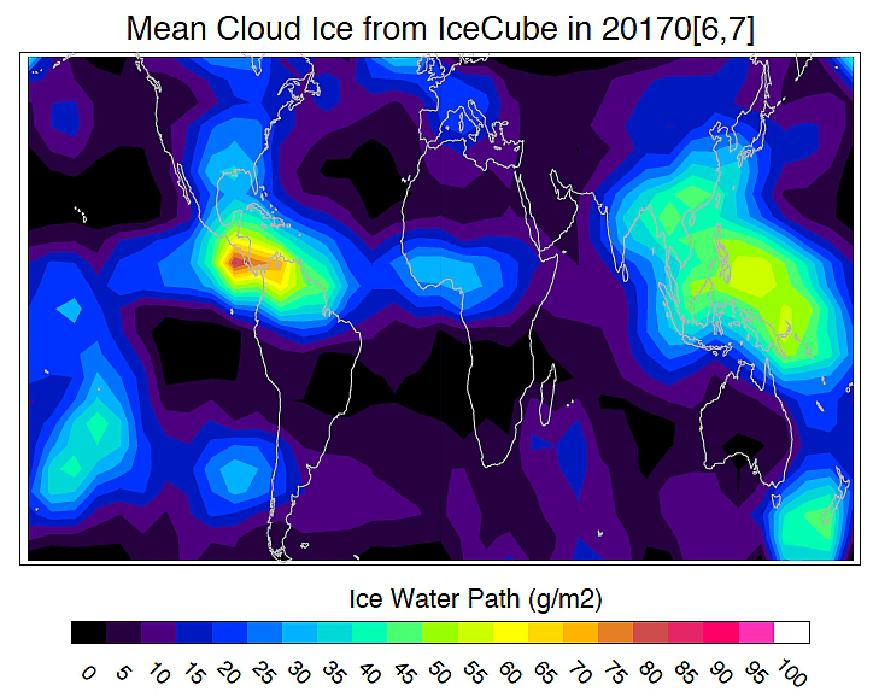
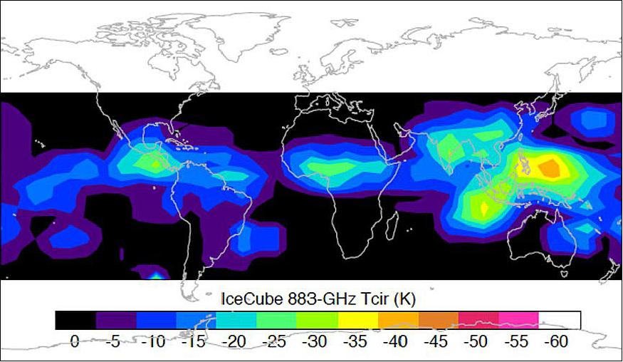
- The spinning CubeSat allows the 883-GHz cloud radiometer to view the Earth's atmosphere and cold space periodically. Frequent space views provide the measurements critical for the radiometric calibration of the receiver system. Figure 19 is the first 883-GHz cloud ice map obtained shortly after IceCube became operational. The 883-GHz radiance, sensitive to ice particle scattering, is proportional to the cloud ice column amount above ~8 km.
The cloud map acquired in June-July 2017 shows a clear distribution of the intertropical convergence zone, as well as the classic Gill-model pattern over the Western Pacific and Indian monsoon regions. After its release from ISS, IceCube has been flying on an orbit similar to ISS, but its orbital height has decreased from 410 km in May 2017 to ~340 km in May 2018. Given its orbit inclination, the coverage of IceCube cloud observations is limited to 52 S – 52 N latitudes.
- Although IceCube was intended as a technology demonstration spacecraft, it has proven that even miniaturized instruments such as this can yield "good enough" science and that CubeSats serve as excellent platforms from which larger, more complex instruments can be designed and implemented in the future. Even though IceCube's radiometer is in flight and acquiring technology and (bonus) science data, its TRL (Technology Readiness Level) stands at 7 as was the original objective: a prototype demonstration carried out in the space environment. A higher TRL instrument, however, would not only observe in the 883 GHz frequency, as now demonstrated on orbit, but also concurrently in other frequencies in order to provide the full range of measurements needed to probe the Earth's atmosphere.
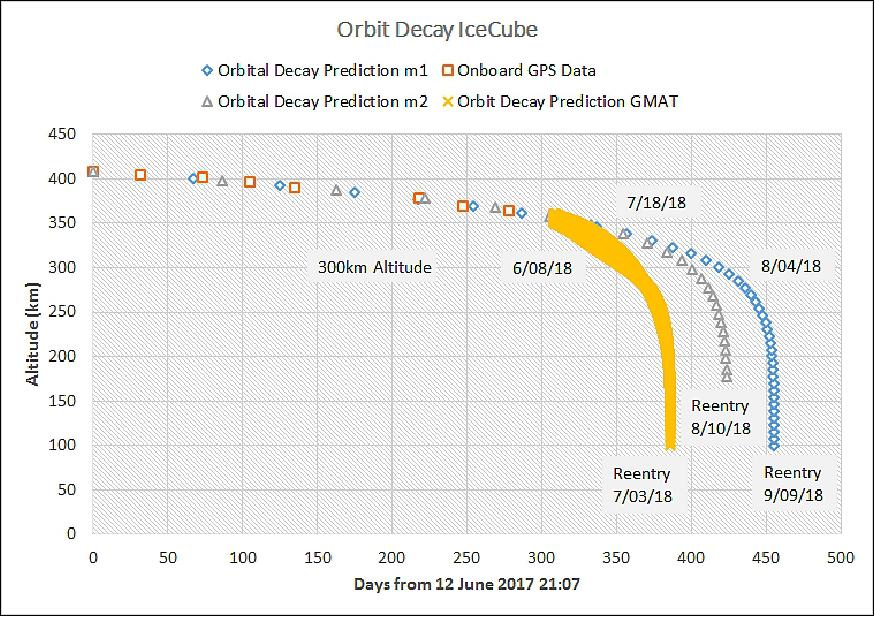
- Lifetime prediction:
IceCube EOL activities will involve a series of experiments to gather instrument and engineering data to determine operational limits, e.g., faster spin rate performance. Between about 300 and 250 km, it is expected that aerodynamic forces will prevent the ACS from effectively controlling the vehicle. At the same time, power from the arrays will become unpredictable, and the battery will no longer provide adequate power for the spacecraft. Once the battery voltage limit is violated, the operations team will command SHM (Safe Hold Mode) and gather as much engineering data as possible prior to ending spacecraft operations.
- Programmatic lessons learned:
Although IceCube's approach was to use as many COTS components as practical, it became apparent that COTS parts are not always "off the shelf". Many COTS subsystems had lead times greater than six months and at least one key subsystem was delivered 8 months later than contracted. This reality was an important contributor to the longer than (originally) anticipated 24-month end-to-end development schedule. Adding to delays, none of the COTS components would "plug and play," and nearly all components had to be modified by the IceCube team and/or returned to the vendor for modification. Finally, the product documentation for the majority of components was found to be incomplete and it was difficult to obtain timely responses from some vendors, particularly those located on separate continents.
- It was quickly learned that staffing IceCube would be challenging. Developing a custom instrument and one-of-a-kind spacecraft would require support from numerous highly skilled engineers and technicians. Originally, it was thought that dedicated multi-skilled software, hardware, and systems engineers would be sufficient if supplemented by subject-matter experts in specific areas. This premise failed to work, and skill sets had to be split among numerous individuals.
Consequently, due to the relatively low level of funding allocated to IceCube, each team member could only support IceCube for a small fraction of their time, with some subsystems seeing a revolving door of engineers as higher priority projects demanded their full attention. This made it very difficult to obtain support in a timely fashion. It was also learned that some implementation approaches, such as software, do not necessarily scale from previous missions, unless designed as such a priori, and require significant changes.
- At the start of IceCube's development several key requirements were not known and many more depended upon the launch manifest, which was not itself known until two years after ATP (Authority to Proceed), and 6 months prior to launch. This caused a great deal of uncertainty in the design and increased costs for both manpower and procurements. For example, the batteries increased in cost by nearly an order of magnitude to make them compliant with ISS man-rated safety requirements.
- IceCube was delivered to the launch vehicle provider 32 months after ATP. Technology development is an inherently risky proposition and any successful endeavour, no matter the roadblocks along the way, is to be commended. Given this experience, there is no doubt the GSFC/WFF (Wallops Flight Facility) team can build high-risk small spacecraft and have them contribute in important ways to the advancement of science and technology.
• May 16, 2018: During a year in orbit, the IceCube ICIR (IceCube Cloud–Ice Radiometer) instrumentation has created a global map of ice clouds around the planet, which could someday help improve models and forecasts. 16)
- Deployed from the ISS in May 2017, IceCube is testing instruments for their ability to make space-based measurements of the small, frozen crystals that make up ice clouds. "Heavy downpours originate from ice clouds," said Dong Wu, IceCube principal investigator at NASA's Goddard Space Flight Center in Greenbelt, Maryland.
- Ice clouds start as tiny particles high in the atmosphere. Absorbing moisture, the ice crystals grow and become heavier, causing them to fall to lower altitudes. Eventually, the particles get so heavy, they fall and melt to form raindrops. The ice crystals may also just stay in the air.
- Like other clouds, ice clouds affect Earth's energy budget by either reflecting or absorbing the Sun's energy and by affecting the emission of heat from Earth into space. Thus, ice clouds are key variables in weather and climate models.
- Measuring atmospheric ice on a global scale remains highly uncertain because satellites have been unable to detect the number of small ice particles inside the clouds, as these particles are too opaque for infrared and visible sensors to penetrate. To overcome that limitation, IceCube was outfitted with a submillimeter radiometer that bridges the missing sensitivity between infrared and microwave wavelengths (Ref. 17).
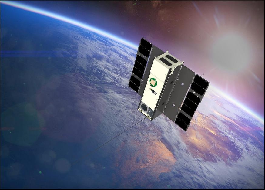
- Despite its mass of ~ 4 kg and is about the size of a loaf of bread, IceCube is a bona fide spacecraft, complete with three-axis attitude control, deployable solar arrays and a deployable UHF communications antenna. The CubeSat spins around its axis, like a plate spinning on a pole. It points at Earth to take a measurement and then looks at the cold space to calibrate.
- Originally a 30-day technology-demonstration mission, IceCube is still fully operational in low-Earth orbit just about a year later, measuring ice clouds and providing data "good enough to do some real science," Wu said.
- "The hard part about developing the CubeSat is making the commercial parts durable in space," said Tom Johnson, Goddard's Small Satellite manager stationed at NASA's Wallops Flight Facility in Virginia. "We bought commercial components for IceCube and spent a lot of time testing the components making sure each part worked."
- Over the past year, engineers tested the satellite's limits while on orbit. They wanted to see if the instrument's batteries stored enough power to run for 24 hours. IceCube charges its batteries when the Sun shines on its solar arrays. During the test, safeguards prevented the satellite from losing all its power and ending the mission; however, the test was successful. The batteries operated the IceCube all night and recharged during the day. This change made CubeSat more valuable for science data collection.
- While the IceCube team planned for the mission to operate for 30 days in space, "It does not cost very much to keep it going," Johnson said, "so we extended the mission due to the outstanding science that IceCube is performing. We download data eight to 10 times a week. Even if we miss a week, the CubeSat can hold a couple of weeks of data."
- The IceCube team built the spacecraft using funding from NASA's Earth Science Technology Office's (ESTO) In-Space Validation of Earth Science Technologies (InVEST) program and NASA's Science Mission Directorate CubeSat Initiative.
- Small satellites, including CubeSats, are playing an increasingly larger role in exploration, technology demonstration, scientific research and educational investigations at NASA. They have been used in planetary space exploration, fundamental Earth and space science, and developing precursor science instruments like cutting-edge laser communications, satellite-to-satellite communications and autonomous movement capabilities.
• January 30, 2018: The IceCube 3U CubeSat has produced the world's first map of the global distribution of atmospheric ice in the 883 GHz band, an important frequency in the submillimeter wavelength for studying cloud ice and its effect on Earth's climate. 17) 18)
- IceCube has demonstrated-in-space a commercial 883 GHz radiometer developed by VDI (Virginia Diodes Inc.) of Charlottesville, Virginia, under a NASA Small Business Innovative Research contract. It is capable of measuring critical atmospheric cloud ice properties at altitudes between 5 -15 km.
- NASA scientists pioneered the use of submillimeter wavelength bands, which fall between the microwave and infrared on the electromagnetic spectrum, to sense ice clouds. However, until IceCube, these instruments had flown only aboard high-altitude research aircraft. This meant scientists could gather data only in areas over which the aircraft flew.
- "With IceCube, scientists now have a working submillimeter radiometer system in space at a commercial price," said Dong Wu, a scientist and IceCube principal investigator at NASA/GSFC (Goddard Space Flight Center) in Greenbelt, Maryland. "More importantly, it provides a global view on Earth's cloud-ice distribution."
- Sensing atmospheric cloud ice requires scientists to deploy instruments tuned to various frequency bands. However, it's particularly important to fly submillimeter sensors. This wavelength fills a significant data gap in the middle and upper troposphere where ice clouds are often too opaque for infrared and visible sensors to penetrate. It also reveals data about the tiniest ice particles that can't be detected clearly in other microwave bands.
- The Technical Challenge:
"IceCube's map is a first of its kind and bodes well for future space-based observations of global ice clouds using submillimeter-wave technology," said Wu, whose team built the spacecraft using funding from NASA's ESTO (Earth Science Technology Office) In-Space Validation of Earth Science Technologies (InVEST) program and NASA's Science Mission Directorate. The team's challenge was making sure the commercial receiver was sensitive enough to detect and measure atmospheric cloud ice using as little power as possible.
- Ultimately, the agency wants to infuse this type of receiver into an ice-cloud imaging radiometer for NASA's proposed ACE (Aerosol-Cloud-Ecosystems) mission. Recommended by the National Research Council, ACE would assess on a daily basis the global distribution of ice clouds, which affect the Earth's emission of infrared energy into space and its reflection and absorption of the Sun's energy over broad areas. Before IceCube, this value was highly uncertain.
- "It speaks volumes that our scientists are doing science with a mission that primarily was supposed to demonstrate technology," said Jared Lucey, one of IceCube's instrument engineers. Lucey, along with a handful of scientists and engineers at Goddard and the Wallops Flight Facility, developed IceCube in just two years with a limited budget. "We met our mission goals and now everything else is bonus."
- Multiple Lessons Learned:
In addition to demonstrating submillimeter-wave observations from space using a commercially available instrument and producing the ice-cloud map, the team gained important insights into how to efficiently develop a CubeSat mission, determining which systems to make redundant and which tests to forgo because of limited funds and a short schedule, said Jaime Esper, IceCube's mission systems designer and technical project manager at Goddard.
- To keep down costs, the team used commercial off-the-shelf components, including, of course, VDI's radiometer. The components came from multiple commercial providers and didn't always work together harmoniously, requiring engineering rework on the part of team members. The team not only integrated the radiometer into the spacecraft, but also built spacecraft ground-support systems and conducted thermal-vacuum, vibration, and antenna testing at Goddard's Greenbelt campus and Wallops' facilities in Virginia.
- "IceCube isn't perfect," Wu conceded, referring to noise or slight errors in the radiometer's data. "However, we can make a scientifically useful measurement. We came away with a lot of lessons learned from this CubeSat project, and next time engineers can build it much more quickly. But under this program, we had to complete the project within a limited budget and schedule, and therefore, we had to take and balance the risks."
- "This is a different mission model for NASA," Wu continued. "Our principal goal was to show that this small mission could be done at NASA. The question was, could we get useful science and advance space technology with a low-cost CubeSat developed under an effective government-commercial partnership? I believe the answer is yes."
- Small satellites, including CubeSats, are playing an increasingly larger role in exploration, technology demonstration, scientific research and educational investigations at NASA, including:
1) planetary space exploration;
2) Earth observations;
3) fundamental Earth and space science;
4) developing precursor science instruments like cutting-edge laser communications, satellite-to-satellite communications and autonomous movement capabilities.
• August 2017: First-light measurements from ICIR were obtained on June 6 with a regular technology demonstration mode starting on June 16 for daytime-only observations. The first 883-GHz cloud radiance map from IceCube (Figure 22) covers the period from June 20 through July 2. As of this writing, IceCube continues to operate normally with the CubeSat spinning around the sun vector in the daytime. The spin produces periodical views between Earth and space, allowing radiometric calibration of ICIR. 19)
• On May 16-17, 2017, NanoRacks began the first of two airlock cycles for the 11th and 12th NanoRacks CubeSat Deployer Missions (NRCSD-11, NRCSD-12). NRCSD-11 and NRCSD-12 were brought to the International Space Station on the Orbital ATK-7 mission, which launched on April 18, 2017, from the Kennedy Space Center in Cape Canaveral, Florida. This launch was the largest CubeSat mission of NanoRacks to date, bringing 34 satellites into the Space Station, plus four CubeSats mounted on externally on the Cygnus spacecraft. 20)
A total of 17 CubeSats were deployed on NRCSD-11 by the NanoRacks Team:
- 11 CubeSats of the QB50 mission were deployed in this first airlock cycle:
SOMP2 – TU Dresden, Germany
HAVELSAT – Havelsan, Turkey
Columbia – University of Michigan, USA
PHOENIX – National Cheng Kung University, Taiwan
X-CubeSat – Ècole Polytechnique, France
QBEE – Open Cosmos Ltd. & University of Lulea, Sweden
ZA-AEROSAT – Stellenbosch University, South Africa
LINK – Korea Advanced Institute of Science and Technology, South Korea
UPSat – University of Patras and Libre Space Foundation, Greece
SpaceCube – Ècole des Mines Paristech, France
Hoopoe – Herzliya Science Center, Israel
- 3 CubeSats were deployed of the NASA ELaNa XVII Sponsored CubeSats:
CXBN-2 of Morehead State University, Morehead, KY
IceCube of NASA/GSFC
CSUNSat-1 of California State University Northridge, NASA/JPL
- Additionally, 3 CubeSats were deployed:
Altair-1 of Millennium Space Systems
SHARC of AFRL (Air Force Research Laboratory)
SG-Sat (Stellar Gyroscope Satellite) of the University of Kentucky.
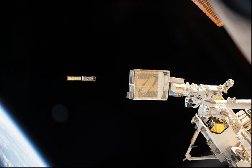
The deployment sequence started about 5 minutes into orbit night, after the prerequisite 30-minute wait time. About 1hr 17min after release, the WFF 18-meter antenna acquired IceCube's beacon telemetry for the first time (Ref. 15).
All systems showed nominal performance. The telemetry also indicated the UHF antenna was deployed on the first attempt, and solar panels deployed after the second attempt (redundant circuit). The ACS was controlling the vehicle in SPM, and spin about the sun-line was at a nominal rate of ~1º/s.
The commissioning phase included a thorough check of all subsystems and an accurate determination of the spacecraft's orbit. The latter turned out to be the most challenging aspect of commissioning. After about 31 orbits (2 days after release), IceCube had drifted far enough from the ISS that predicting its position within the narrow 3º ground antenna beam became uncertain. Therefore, telemetry was lost and was not acquired until a NORAD TLE (Two-Line Element) became available and IceCube was identified among the cluster of CubeSats deployed from the ISS at the same time.
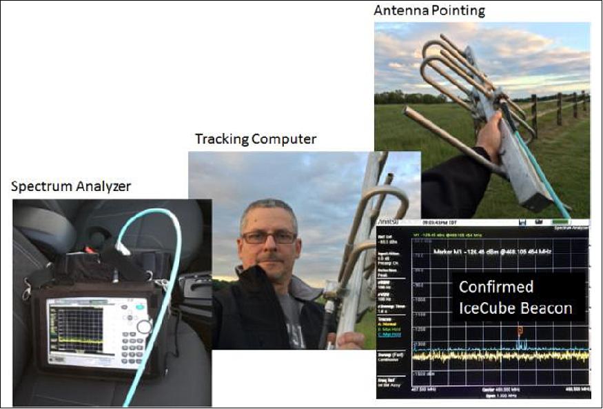
In order to determine the spacecraft's fate after initial telemetry loss, a crude "ground system" was set up to receive beacon signals. A 7.5 dBi, 45º beam Yagi antenna connected to a portable spectrum analyzer was trained in the general direction of the predicted position of IceCube. A beacon signal with a signature similar to IceCube's last known transmission was detected after several tries, and 7 days after contact was lost.
This was soon confirmed by NORAD's TLE, and the commissioning phase could begin in earnest. Figure 24 shows the crude setup used. The low gain antenna and imprecise tracking were sufficient to detect at least one beacon per pass and point to the use of greater beam ground systems for initial acquisition and tracking of LEO CubeSats in the future, or for contingency searches.
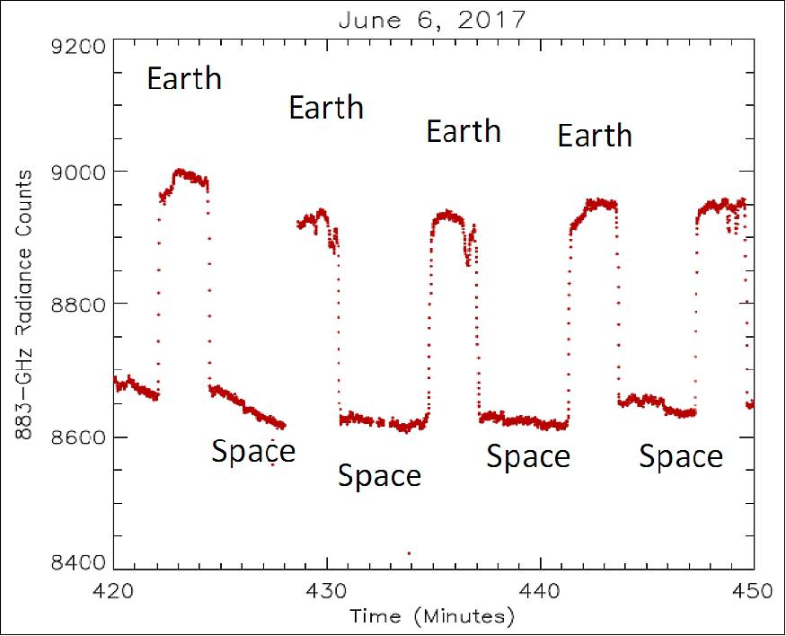
The IceCube 883-GHz cloud radiometer was powered-on for two orbits on June 6 2017, or about three weeks after its initial release. The instrument showed good sensitivity to Earth and space scenes (Figure 25). All data indicated that both the spacecraft and the instrument were healthy, and the cloud radiometer could begin technology validation.
Ground Station
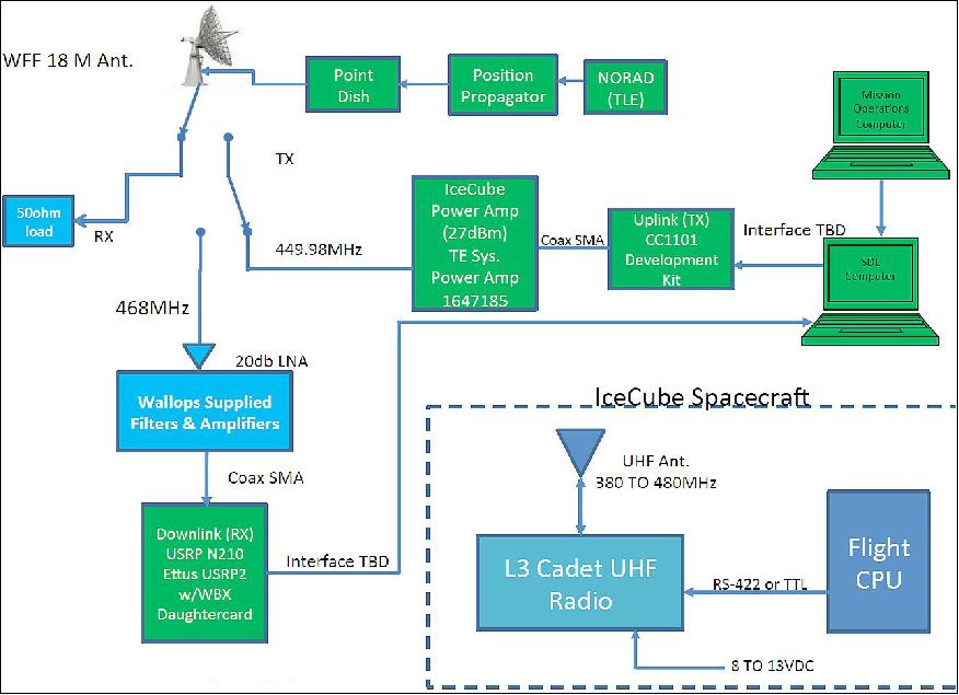
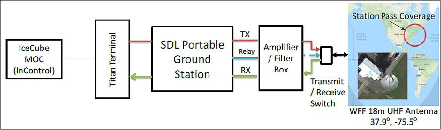
The IceCube ground station consists of a single computer located in the MOC (Mission Operations Center) that uses L3's InControl Software, and an SDL (Space Dynamics Lab) Titan system located at the UHF antenna site. This system is designed to allow the MOC computer to connect to Titan and establish communication between the MOC, UHF antenna, and the IceCube spacecraft (Figure 26). Once this connection is made commanding and telemetry downlinks are possible.
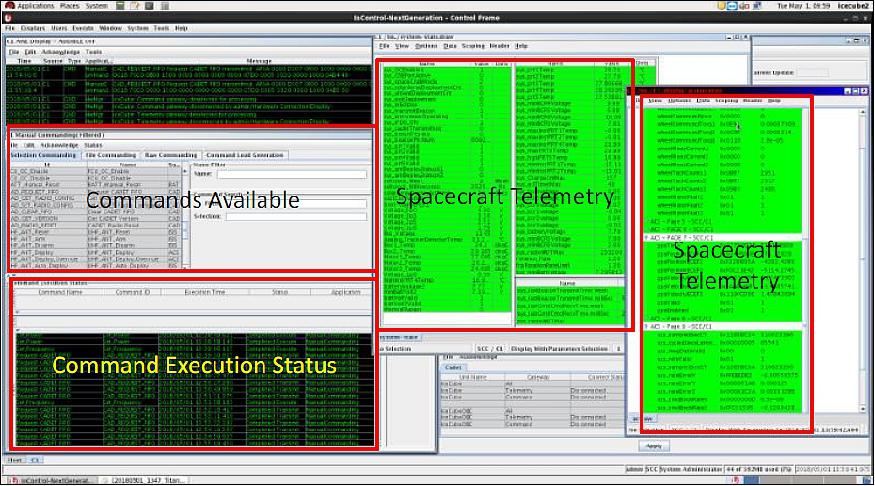
Command and telemetry databases were created to define command and telemetry formats. Information pages provide users with the commands available and display downlinked telemetry data received (Figure 27). The IceCube ground station was configured such that the integration and test teams could perform RF communications with the Cadet Radio along with internet access to the IceCube umbilical during development. All downlinked data is archived on the MOC computer, and a data extraction application allows archived pass data to be extracted and distributed to PDLs (Project Design Leads) and the science team.
References
1) D. L. Wu, J. Esper, N. Ehsan, T. E. Johnson, W. R. Mast, J. R. Piepmeier, P. E. Racette, "IceCube: Spaceflight Validation of an 874 GHz Submillimeter Wave Radiometer for Cloud Ice Remote Sensing," ESTF 2014 (Earth Science Technology Forum), Leesburg, VA, USA, Oct. 28-30, 2014, URL: http://esto.nasa.gov/forum/estf2014/presentations/B1P5_Wu.pdf
2) Lori Keesey, "NASA's IceCube No Longer On Ice," NASA, July 30, 2014, URL: http://www.nasa.gov/content/goddard/nasas-icecube-no-longer-on-ice/#.VMpRnC7-b-Y
3) Jaime Esper, Dong Wu, Jeffrey Piepmeier, Negar Ehsan, Paul Racette, "Ice-Cube: Spaceflight Validation of an 874 GHz Sub-millimeter Wave Radiometer for Ice Cloud Remote Sensing," 10th IAA Symposium on Small Satellites for Earth Observation, Berlin, Germany, April 20-24, 2015, paper: IAA-B10-0303, URL of presentation: http://www.dlr.de/iaa.symp/Portaldata/49/Resources/dokumente/archiv10/pdf/0303.pdf
4) K. Franklin Evans, James R. Wang, Paul E. Racette, Gerald Heymsfield, Lihua Li, "Ice Cloud Retrievals and Analysis with the Compact Scanning Submillimeter Imaging Radiometer and the Cloud Radar System during CRYSTAL FACE," Journal of Applied Meteorology and Climatology, Volume 44, Issue 6,June 2005), pp: 839–859, URL: http://journals.ametsoc.org/doi/pdf/10.1175/JAM2250.1
5) D. L. Wu, J. Esper, N. Ehsan, T. E. Johnson, W. R. Mast, J. R. Piepmeier and P. E. Racette, "IceCube: CubeSat883-GHz Radiometry for Future Cloud Ice Remote Sensing," Earth Science Technology Forum, Pasadena, CA, June 25, 2015, URL: https://ntrs.nasa.gov/archive/nasa/casi.ntrs.nasa.gov/20150021071.pdf
6) "NASA Space Station Cargo Launches aboard Orbital ATK Resupply Mission," NASA, Release 17-029, April 18, 2017, URL: https://www.nasa.gov/press-release/nasa-space-station-
cargo-launches-aboard-orbital-atk-resupply-mission
7) Jeff Foust, "Orbital to launch next Cygnus mission on Atlas 5," Space News, Nov. 4, 2016, URL: http://spacenews.com/orbital-to-launch-next-cygnus-mission-on-atlas-5/
8) "United States Commercial ELV Launch Manifest," Dec. 28, 2016, URL: http://www.sworld.com.au/steven/space/uscom-man.txt
9) Eamonn P. Glennon, Joseph P. Gauthier, Mazher Choudhury, Kevin Parkinson, Andrew G. Dempster, "Project Biarri and the Namuru V3.2 Spaceborne GPS Receiver," IGNSS (International Global Navigation Satellite Systems Society) Symposium 2013, Outrigger Gold Coast, Australia, 16 – 18 July 2013, URL: https://pdfs.semanticscholar.org/3d15/3f47ef0f39f21acb3649ab92afef72b53aea.pdf
10) Jacob A. LaSarge, "A CubeSat mission for mapping spot beams of geostationary communication satellites," Thesis, March 2015, URL: http://www.dtic.mil/get-tr-doc/pdf?AD=ADA617698
11) Davide Masutti, "QB50-ISS CubeSats ready to be launched," Dec. 9, 2016, URL: https://www.qb50.eu/index.php/news/78-qb50-iss-ready-to-be-launched
12) US Commercial ELV Launch Manifest, March 5, 2017, URL: http://www.sworld.com.au/steven/space/uscom-man.txt
13) "IceCube," NASA, Climate & Radiation, 3 September 2019, URL: https://atmospheres.gsfc.nasa.gov/climate/index.php?section=259
14) Jaime Esper, Dong Wu, Brian Abresch, Brooks Flaherty, Chris Purdy, John Hudeck, Juan Rodriguez, Ted Daisey, Scott Heatwole, Robert Stancil, Thomas Johnson, Alexander Coleman, Negar Ehsan, Kevin Horgan, Jeffrey Piepmeier, "NASA IceCube: CubeSat Prototyping of a 883 GHz Radiometer for Cloud Ice Mapping," Proceedings of the 12th IAA Symposium on Small Satellites for Earth Observation, Berlin, Germany, 06-10 May 2019, IAA-B12-0801
15) Jaime Esper, Dong Wu, Brian Abresch, Brooks Flaherty, Chris Purdy, John Hudeck, Juan Rodriguez, Ted Daisey, Scott Heatwole, Robert Stancil, Thomas Johnson, Alexander Coleman, Negar Ehsan, Kevin Horgan, Jeffrey Piepmeier, "NASA IceCube: CubeSat Demonstration of a Commercial 883-GHz Cloud Radiometer," Proceedings of the 32nd Annual AIAA/USU Conference on Small Satellites, Logan UT, USA, Aug. 4-9, 2018, paper: SSC18-I-02, URL: https://digitalcommons.usu.edu/cgi/viewcontent.cgi?article=4063&context=smallsat
16) Rani Gran, "Tiny Satellite's First Global Map of Ice Clouds," NASA, 16 May 2018, URL: https://www.nasa.gov/feature/goddard/2018/tiny-satellites-first-global-map-of-ice-clouds
17) Lori Keesey, "NASA's Small Spacecraft Produces First 883-Gigahertz Global Ice-Cloud Map," NASA, 30 Jan. 2018, URL: https://www.nasa.gov/feature/goddard/2018/nasa-s-small-
spacecraft-produces-first-883-gigahertz-global-ice-cloud-map
18) "Bread Loaf-Sized Spacecraft Exceeds Expectations — Produces First 883-Gigahertz Global Ice-Cloud Map," cutting edge, Vol. 14, Issue 2, Winter 2018, pp: 10-11, URL: https://www.nasa.gov/sites/default/files/atoms/files/winter_2018_final_lowrez.pdf
19) Steve Platnick, "Editor's Corner," The Earth Observer. July - August 2017. Volume 29, Issue 4., pp: 1-2, " URL: https://eospso.gsfc.nasa.gov/sites/default/files/eo_pdfs/July
%20August%202017%20color%20508.pdf
20) "NanoRacks CubeSat Deployer Mission 11 Status Update: Good Deploy!," NanoRacks, May 17, 2017, URL: http://nanoracks.com/cubesat-deployer-mission-11-update/
The information compiled and edited in this article was provided by Herbert J. Kramer from his documentation of: "Observation of the Earth and Its Environment: Survey of Missions and Sensors" (Springer Verlag) as well as many other sources after the publication of the 4th edition in 2002. - Comments and corrections to this article are always welcome for further updates.
IceCube Radiometer Spacecraft Launch Mission Status Ground Segment References Back to top