HY-1A (Haiyang-1A) / Ocean-1A
EO
Ocean colour instruments
Ocean
Ocean colour/biology
Quick facts
Overview
| Mission type | EO |
| Agency | CAST, NSOAS |
| Mission status | Mission complete |
| Launch date | 15 May 2002 |
| End of life date | 30 Mar 2004 |
| Measurement domain | Ocean, Land, Snow & Ice |
| Measurement category | Ocean colour/biology, Multi-purpose imagery (land), Albedo and reflectance, Surface temperature (ocean), Sea ice cover, edge and thickness |
| Measurement detailed | Land surface imagery, Earth surface albedo, Sea surface temperature, Ocean suspended sediment concentration, Sea-ice cover |
| Instruments | COCTS, CZI |
| Instrument type | Ocean colour instruments, Imaging multi-spectral radiometers (vis/IR) |
| CEOS EO Handbook | See HY-1A (Haiyang-1A) / Ocean-1A summary |
HY-1A (Haiyang-1A) / Ocean-1A
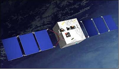
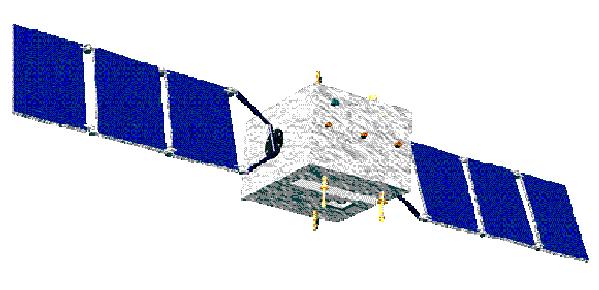
Haiyang-1 is a Chinese minisatellite mission designed/developed by CAST (Chinese Academy of Space Technology) and sponsored by the State Ocean Administration (SOA), Beijing, China. This satellite was developed on a common minisatellite platform, namely CAST968, also employed by the SJ-5 satellite (Shi Jian-5, launch May 10, 1999). HY-1 is China's first satellite for surveying ocean resources (ocean color and sea surface temperature) and monitoring the environment.
Note: The HY-2 satellite series, under development in China with a first launch planned for 2009, is a parallel series to HY-1. The objective of the HY-2 series is to monitor the dynamic ocean environment (observations mainly in the microwave region); hence, it will fly such instruments as an altimeter (sea surface height), a scatterometer (sea surface wind field), and a microwave imager (microwave brightness temperature).
Spacecraft
The structure of the spacecraft is based on the multi-mission CAST968 bus, a box-shaped satellite with overall dimensions of 1.2 m x 1.1 m x 0.94 m. The total deployed length of HY-1 is about 7.5 m. The S/C is three-axis stabilized (Earth pointing) using three magnetorquers and hydrazine propulsion for attitude control and orbit change maneuvers; the attitude accuracy is 0.4º in roll and pitch and 0.5º in yaw. Attitude sensing is provided by a sun sensor and an infrared Earth sensor.
S/C power of 450 W (BOL) and 320 W (EOL) is provided by two solar arrays of size 5.67 m2. In addition, there are two packs of NiCd batteries of 23 Ah for night phase power supply. Electrical heaters are used for active thermal control. The S/C mass is 367 kg (including 13kg of propellant); payload mass = 87 kg; the design life is two years. 1) 2)
RF Communication
The TT&C communication is in S-band, the downlink date rate is 4 kbit/s, the uplink rate is 2 kbit/s. An onboard storage capacity of 80 Mbit is provided. All payload data are downlinked in X-band using QPSK modulation at a data rate of 5.32 Mbit/s, EIRP = 39.4 dBm. The HY-1 payload data are being acquired at the Beijing and the Sanya ground receiving stations in China.
Launch
A launch of HY-1A as secondary payload, along with FY-1D as the primary payload, took place on May 15, 2002 on a LM-4B launch vehicle from the Taiyuan launch site in China.
Orbit
Sun-synchronous near-circular orbit, altitude = 798 km, inclination =98.8º; nodal period = 100.8 minutes; the local time at the descending node is between 9:00 and 10:10 hours (at the end of two year's life). The revisit time for the Ocean Color Scanner is three days; the revisit time for the CCD Camera is seven days.
Status of the HY-1A Mission
• The spacecraft provided an operational service for 685 days, from May 2002 to April 2004, with an operational life somewhat shorter than the nominal design life of two years.
• The CZI sensor stopped working on Dec. 1, 2003, after 17 months of operation, because of power problems. 3)
Sensor Complement
The data user of both instruments is SOA (State Ocean Administration) as well as all institutes in China dealing with marine data processing.
COCTS (Chinese Ocean Color and Temperature Scanner)
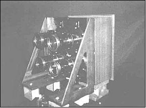
COCTS is a medium-resolution optical imager developed by SITP (Shanghai Institute of Technical Physics) of CAS (China Academy of Sciences), China. The objective is global ocean color monitoring for the study of biological oceanography, including chlorophyll concentration, suspended sediment concentration, dissolved organic matter, pollutants, as well as sea surface temperature. COCTS consists of the following subsystems: optics, scanner, FPA (Focal Plane Array) and an electronics box. Imagery is provided in 8 VNIR (Visible Near Infrared) and in two TIR (Thermal Infrared) bands with a spatial resolution of 1.1 km. The swath width is 1400 km. The instrument data rate is 0.67 Mbit/s. 4) 5) 6) 7) 8)
The design characteristics of COCTS are similar to those of SeaWiFS (Sea-Viewing Wide Field-of-View Sensor) flown on the OrbView-2 mission of ORBIMAGE (launch Aug. 1, 1997), and to those of OCTS (Ocean Color and Temperature Scanner) flown on ADEOS (launch Aug. 17, 1996).
Pixel resolution | 1.1 km (nadir) | |
FOV (swath), Pixels per scan line | ±35.2º (~1400 km), 1024 | |
Focal length of optical system | 650 mm for VNIR, 190 mm for TIR | |
Telescope aperture diameter | 200 mm | |
Detectors | Si for VNIR, HgCdTe for TIR | |
Whiskbroom instrument | Scan mirror assembly; there are four parallel scan lines along-track | |
Deviation of central wave length | 2 nm | |
Data quantization | 10 bit | |
Cooling temperature | 80 K for TIR band | |
Instrument mass, power | 50 kg, average = 29.3 W, peak = 41.7 - 71.7 W | |
Spectral bands (µm) | SNR | Dynamic range (%) | Observation objective |
0.402 - 0.422 | 440 | 40 | Yellow substance, water pollution |
0.433 - 0.453 | 600 | 35 | Absorption of chlorophyll |
0.480 - 0.500 | 590 | 30 | Chlorophyll, sea water optics sea ice |
0.510 - 0.530 | 560 | 28 | Chlorophyll, water depth, |
0.555 - 0.575 | 525 | 25 | Chlorophyll, sediment of low concentration |
0.660 - 0.680 | 390 | 20 | Peak of fluorescence, sediment of high concentration, pollution, atmospheric correction, aerosols |
0.745 - 0.785 | 400 | 15 | Sediment of high concentration, atmospheric correction |
0.845 - 0.885 | 415 | 15 | Atmospheric correction, water vapor |
10.30 - 11.40 (TIR) | NEΔT = 0.2 K (at 300 K) | SST (Sea Surface Temperature), sea ice, temperature of cloud top | |
11.40 - 12.50 (TIR) | NEΔT = 0.2 K (at 300 K) | SST, sea ice, temperature of cloud top | |
In-flight calibration of COCTS
Although there is an onboard calibration system for the TIR (Thermal Infrared) bands of COCTS, it has experienced some aging after in-flight operations for one year. To validate the onboard calibration system, a target on Earth is selected to calibrate the TIR bands. The calibration method of Palmer and Slater, using the normalized water-leaving radiance and aerosol parameters derived for SeaWiFS, has already been successfully demonstrated. 9) 10)
In China, Lake Qinhai is the most suitable site for calibrating thermal infrared bands of various satellite sensors. A team lead by NSMC (National Satellite Meteorology Center), Beijing, performed the TIR-band calibration experiments in the period Aug. 8-15, 2003. This method was also used to supervise the calibration coefficient of COCTS. 11) 12)
CZI (Coastal Zone Imager)
CZI is a multispectral pushbroom CCD instrument developed by the Beijing Institute of Space Machines and Electricity, a facility of CAST. The objective is to provide in particular imagery of coastal regions (estuaries, tidal waters, monitoring of pollution, etc.). CZI has a repeat period of 7 days.
Note: the instrument is also referred to as the “4-band CCD Imager.” 13)
Spectral ranges (µm), 4 bands | 0.42 - 0.50, (pollution, vegetation, ocean color, sea ice) |
Pixel resolution, number of pixels per line | 250 m (nadir), 2048 |
Pixel size (µm) | 10 x 10 |
Focal length of optical system | 32 mm |
FOV (Field of View), swath width | 36º, or 500 km swath width |
Deviation of center wavelength | < 5 nm |
SNR | 641 |
Data quantization | 12 bit |
Instrument mass, power | 15 kg, average = 6 W, peak = 30 W |
Instrument data rate | 2.67 Mbit/s |
References
1) Information provided by Lihua Zhang of CAST and by Mingsen Lin of SOA, Beijing, China
2) Xingwei Jiang, Mingsen Lin, Jiangqiang Liu, “HY-1 satellite and its application in China,” AARS (Asian Association on Remote Sensing) 2004, Chiang Mai, Thailand, Nov. 22-24, 2004, URL: http://www.a-a-r-s.org/acrs/proceeding/ACRS2004/Papers/ANS04-1.htm
3) Report of Pan Delu of SOA to the 9th IOCCG Committee Meeting, Jan. 15-17, 2004, Hyderabad, India, http://www.ioccg.org/reports/ioccg_meeting9.html
4) Q. Feng, Q.-B, Zheng, H.-X. Gong “10-Bands Ocean Color and Temperature Scanner,” ACRS (Asian Conference on Remote Sensing), Hong Kong, China, Nov. 22-25, 1999
5) P. Delu, H. Xinqing. “Development of ocean color remote sensing in China in 2002,” 8th IOCCG Meeting, Florence, Italy, Feb. 24-26, 2003, URL: http://www.ioccg.org/sensors/chinese/development.ppt
6) Pan Delu, “Satellite marine remote sensing in China,” Proceedings of the SPIE, Vol. 4892, 2003, pp. 1-16 , `Ocean Remote Sensing and Applications,' Edited by Robert J. Frouin, Yuan, Yeli, Kawamura, Hiroshi
7) Shujing Li, Mao Tianming, Pan Delu, “A Study on the Quality and Availability of the COCTS Images of HY-1 Satellite by Simulation,” WOM-13, 13th Workshop of OMISAR (Ocean Model and Information System for APEC Region), Bali Indonesia, Oct. 5-9, 2004, URL: http://sol.oc.ntu.edu.tw/omisar/wksp.mtg/WOM13/wom13www/01-06Shujingy%20Li%20full%20paper.doc
8) Chaofei Ma, Chenyang Li, Qiamao Wang, “The Typical Applications of HY-1 Satellite Data on the Oceanography,” 14th OMISAR Workshop on Ocean Models (WOM-14), Oct. 26-29, 2004, Tainan, Chinese Taipei, URL: http://ivy3.epa.gov.tw/OMISAR/Data/WOM14/proceedings/3.pdf
9) P. N. Slater, S. F. Biggar , K. J. Thome, D. I. Gellman, P. R. Spyak, “Vicarious radiometric calibrations of EOS sensors[J], Journal of Atmospheric and Oceanic Technology, 1996, Vol. 13, No 2, 1996, pp. 349-359
10) J. M. Palmer, “Calibration of satellite sensors in the thermal infrared [C], Proceedings of .SPIE, 1993, Vol. 1762: pp. 108-117
11) J. Tong, K. Qiu, X. Li, “Absolute Radiometric Calibration for Thermal Infrared Bands of HY-1/COCTS by Using Qinhai Lake,” Proceedings of IGARSS 2004, Anchorage, AK, USA, Sept. 20-24, 2004
12) J. Tong, K. Qiu, X. Li, J. Qin, Y. Zhang, X. Hu, “Absolute Radiometric Calibration of HY-1 COCTS Using the Reflectance-based Method,” Proceedings of IEEE/IGARSS 2003, Toulouse, France, July 21-25, 2003 .
13) Yufeng Zhang, Shiping Chen, Min Zhu, Shengli Zhou, Yanlin Wu, “Preflight Calibration of HY-1 Satellite 4-band CCD Camera,” 22nd Asian Conference on Remote Sensing, November 5-9, 2001, Singapore, URL: http://www.crisp.nus.edu.sg/~acrs2001/pdf/300Zhang.pdf
The information compiled and edited in this article was provided by Herbert J. Kramer from his documentation of: ”Observation of the Earth and Its Environment: Survey of Missions and Sensors” (Springer Verlag) as well as many other sources after the publication of the 4th edition in 2002. - Comments and corrections to this article are always welcome for further updates (eoportal@symbios.space).