GPIM (Green Propellant Infusion Mission)
EO
Ocean
Multi-purpose imagery (ocean)
NASA
Quick facts
Overview
| Mission type | EO |
| Agency | NASA |
| Mission status | Mission complete |
| Launch date | 25 Jun 2019 |
| End of life date | 14 Oct 2020 |
| Measurement domain | Ocean, Land |
| Measurement category | Multi-purpose imagery (ocean), Multi-purpose imagery (land) |
| Measurement detailed | Oil spill cover |
| Instrument type | Earth radiation budget radiometers, Other, Data collection |
| CEOS EO Handbook | See GPIM (Green Propellant Infusion Mission) summary |
GPIM (Green Propellant Infusion Mission)
Spacecraft Launch Mission Status Sensor Complement References
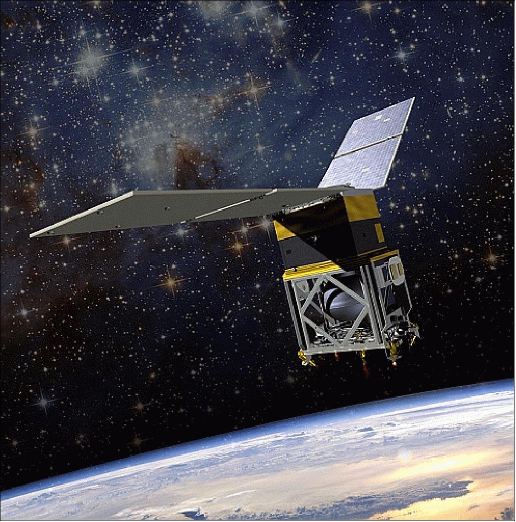
GPIM is a NASA technology demonstration mission. The objective is to test the practical capabilities of a Hydroxyl Ammonium Nitrate fuel/oxidizer blend, known as “AF-M315E.” This innovative, low-toxicity propellant, developed by the U.S. AFRL (Air Force Research Laboratory) at Edwards Air Force Base, CA, is a high-performance, green alternative to hydrazine. 1) 2) 3)
NASA and BATC (Ball Aerospace & Technologies Corporation) of Boulder, CO, are collaborating on the GPIM mission, which seeks to improve overall propellant efficiency while reducing the toxic handling concerns associated with the highly toxic fuel, hydrazine. The space technology infusion mission also strives to optimize performance in new hardware, system and power solutions while ensuring the best value for investment and the safest space missions possible.
NASA and its partners always strive to maintain the strictest safety standards for storage, transport and use of rocket propellants. While all rocket fuels can be dangerous to handle without the proper safety precautions, AF-M315E has significantly reduced toxicity levels compared to hydrazine, making it easier and safer to store and handle. It also requires fewer handling restrictions and potentially shorter launch processing times, resulting in lowered costs.
AF-M315E also is expected to improve overall vehicle performance. It boasts a higher density than hydrazine, meaning more of it can be stored in containers of the same volume. In addition, it delivers a higher specific impulse, or thrust delivered per given quantity of fuel, and has a lower freezing point, requiring less spacecraft power to maintain its temperature.
The GPIM payload will fly to space aboard a Ball compact small satellite. During the test flight, researchers will conduct orbital maneuvers to demonstrate the performance of the propellant during attitude control shifts, changes in orbital inclination and orbit lowering.
The GPIM project is managed by NASA/MSFC (Marshall Space Flight Center) in Huntsville, AL.
Spacecraft
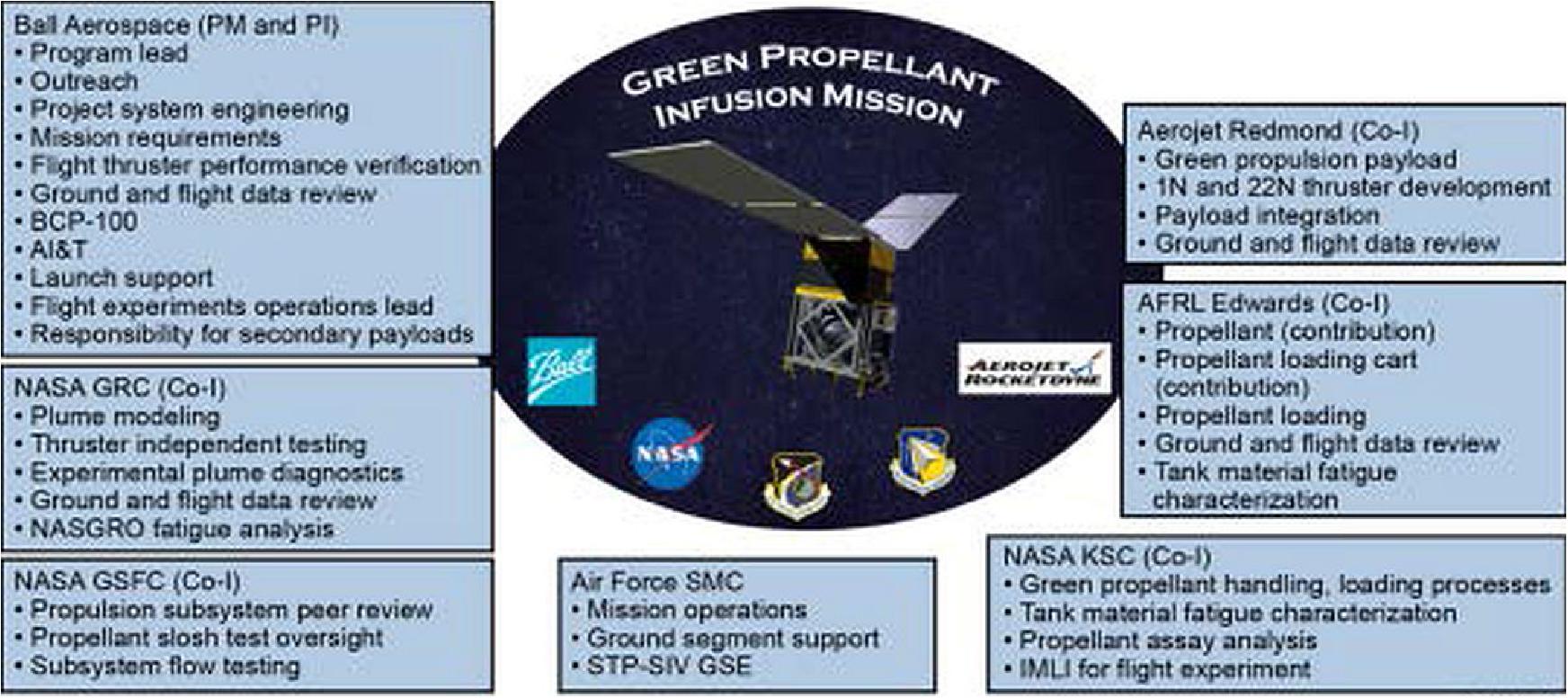
BATC (Ball Aerospace & Technologies Corp.) of Boulder, CO, is the prime contractor for GPIM and is leading the demonstration of the alternative fuel for future space vehicles. The team includes Aerojet Rocketdyne of Sacramento, CA; the U.S. AFRL (Air Force Research Laboratory) at Edwards AFB, CA; the Air Force SMC (Space and Missile Systems Center) at Kirtland Air Force Base, NM.; and two NASA field centers: NASA/GRC (Glenn Research Center) in Cleveland, OH, and NASA/KSC (Kennedy Space Center), FL.
The GPIM spacecraft is using the BCP-100 (Ball Configurable Platform 100) standard interface bus. This bus is of STP-SIV (Space Test Program-Standard Interface Vehicle) bus heritage of BATC, flown on the STP-S26/STPSat-2 and the ORS-3/STPSat-3 missions of the USAF. The small, modular spacecraft was designed to interface with an EELV (Evolved Expendable Launch Vehicle) ESPA (Secondary Payload Adapter), where it can be launched as a secondary payload.
GPIM has been selected to test an advanced form of thermal insulation, called IMLI (Integrated Multi-Layer Insulation) that could become standard on future satellites and cryogenic subsystems. Validating this new insulation in space will help NASA build the technology required for long human spaceflight missions. Under a subcontract from Ball Aerospace & Technologies Corp., Quest Thermal Group LLC will manufacture the new insulation that will fly aboard the GPIM mission. 4)
Test of the capabilities of a high-performance, non-toxic, “green” fuel on orbit: The fuel and its accompanying technology offer many advantages for future satellites, including longer mission durations, additional maneuverability, increased payload space, and simplified launch processing. The propellant for this mission is a HAN (Hydroxyl Ammonium Nitrate) fuel/oxidizer blend, or AF-M315E. Developed by AFRL (Air Force Research Laboratory) at Edwards Air Force Base, it offers nearly 50 percent higher performance for a given propellant tank volume compared to a conventional hydrazine system. This new, green propellant is less harmful to the environment, increases fuel efficiency, and diminishes operational hazards. 5)
The mass of of the GPIM spacecraft is ~180 kg.
Development Status
• May 21, 2019: Ball Aerospace, a partner in the new NASA Green Propellant Infusion Mission (GPIM) announced their Ball Aerospace-built small spacecraft arrived in Florida today to prepare for a June launch on board a SpaceX Falcon Heavy rocket. GPIM is NASA's first opportunity to demonstrate a new "green" propellant and propulsion system in orbit – an alternative to conventional chemical propulsion systems. 6)
- GPIM is a sustainable and efficient approach to spaceflight, and the new propellant will demonstrate the practical capabilities of a Hydroxyl Ammonium Nitrate fuel and oxidizer blend, called AF-M315E. This innovative, low toxicity, "green" propellant was developed by the Air Force Research Laboratory. GPIM is part of NASA's Technology Demonstration Missions program within the Space Technology Mission Directorate.
- Dr. Makenzie Lystrup, vice president and general manager, Civil Space, Ball Aerospace stated that GPIM was a truly collaborative effort, working with their partners, NASA, Aerojet Rocketdyne, Air Force Research Laboratory, U.S. Air Force and SpaceX. They are proud to be part of this historic mission to test a new 'green' propellant on board Ball's flight-proven small satellite, helping to provide science at any scale.
- Ball Aerospace is responsible for system engineering; flight thruster performance verification; ground and flight data review; spacecraft bus; assembly, integration and test; and launch and flight support. The GPIM bus uses the smallest of the Ball Configurable Platform (BCP) satellites, which is about the size of a mini refrigerator, and was built in just 46 days. The BCP provides standard payload interfaces and streamlined procedures, allowing rapid and affordable access to space with flight-proven performance.
• March 31, 2016: GPIM recently took another major step toward demonstrating the capabilities of a new propellant that is safer to handle on the ground and more efficient for thrusters in space. The GPIM spacecraft has passed a major flight readiness milestone marking the successful completion of functional and environmental testing of its systems and software, and is on track for launch in early 2017. 7)
• Oct. 5, 2015: The propulsion subsystem for NASA's Green Propellant Infusion Mission has been integrated onto the spacecraft, moving the mission another major step toward scheduled launch in 2016. 8)
• August 19, 2015: NASA's Green Propellant Infusion Mission to develop a high-performance, low-toxicity fuel and propulsion system for spacecraft has passed a major milestone. A green propellant propulsion subsystem, built by Aerojet Rocketdyne in Redmond, Washington, has been delivered to the mission’s prime contractor, BATC (Ball Aerospace & Technologies Corp.) in Boulder, Colorado. 9)
- The green propellant propulsion subsystem consists of a propellant tank and five 1 N thrusters that will use the new fuel. Because AF-M315E burns hotter than hydrazine, it required new metals to withstand the temperatures in the thrusters aboard the propulsion system.
• The PDR (Preliminary Design Review), held July 23-24, 2013 at Ball, demonstrated that the project met all requirements with acceptable risk and within cost and schedule constraints, and established the basis for proceeding with detailed design. 10)
Launch
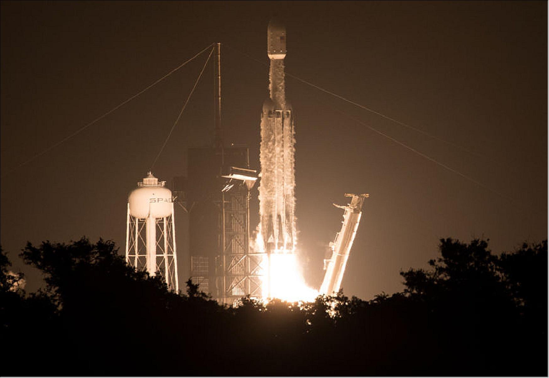
GPIM of NASA is a secondary payload on the STP-2 rideshare mission of USAF, launched on 25 June 2019 (06:30 UTC) aboard a SpaceX Falcon Heavy launch vehicle from Launch Complex 39A at NASA’s Kennedy Space Center. The STP-2 payload includes six FormoSat-7/COSMIC-2 satellites (primary payload, each with a mass of 280 kg), developed by NOAA and Taiwan’s National Space Organization to collect GPS radio occultation data for weather forecasting. The STP-2 mission is led by the Air Force Space Command’s Space and Missile Systems Center (SMC). The total IPS (Integrated Payload Stack) has a mass of 3700 kg. 11) 12)
Secondary Payloads
• DSX (Demonstration and Science Experiments) mission of AFRL
• GPIM (Green Propellant Infusion Mission), a demonstration minisatellite of NASA (~180 kg). 13)
• FalconSat-7, a 3U CubeSat mission developed by the Cadets of the U.S. Air Force Academy (USAFA) at Colorado Springs, CO.
• NPSat-1 (Naval Postgraduate School Satellite-1) of the Naval Postgraduate School, Monterey, CA. A microsatellite of 86 kg.
• OCULUS-ASR (OCULUS-Attitude and Shape Recognition), a microsatellite (70 kg) of MTU (Michigan Technological University), Houghton, MI, USA.
• Prox-1, a microsatellite (71 kg) of SSDL (Space Systems Design Laboratory) at Georgia Tech.
• LightSail-2 of the Planetary Society, a nanosatellite (3U CubeSat, 5 kg) will be deployed from the parent satellite Prox-1.
• ARMADILLO of UTA (University of Texas at Austin), a nanosatellite (3U CubeSat) of ~ 4 kg.
• E-TBEx (Enhanced Tandem Beacon Experiment), a tandem pair (3U CubeSats) of SRI International.
• Prometheus-2.1 to -2.8, seven 1.5U CubeSats (each of 2 kg) of LANL (Los Alamos National Laboratory).
• TEPCE (Tether Electrodynamics Propulsion CubeSat Experiment), a 3U CubeSat (3 kg) of NPS (Naval Postgraduate School).
• CP-9 , a joint CP-9/StangSat experiment, which is a collaboration between PolySat at Cal Poly and the Merritt Island High School, and is sponsored by the NASA LSP (Launch Services Program). CP-9 is a 2U CubeSat while StangSat is a 1U CubeSat.
• PSat-2 (ParkinsonSat-2), a student built 1.5U CubeSat of USNA (US Naval Academy) with a mass of 2 kg.
• BRICSAT-2, a student built 1.5U CubeSat of USNA (US Naval Academy) to demonstrate a µCAT electric propulsion system and carry a ham radio payload.
• OTB-1 (Orbital Test Bed-1) a minisatellite of SSTL (based on the SSTL-150 bus, 138 kg). One of the hosted payloads is NASA's DSAC (Deep Space Atomic Clock), a technology demonstration mission with the goal to validate a miniaturized, ultra-precise mercury-ion atomic clock that is 100 times more stable than today’s best navigation clocks.
Orbits
The STP-2 mission will be among the most challenging launches in SpaceX history with four separate upper-stage engine burns, three separate deployment orbits, a final propulsive passivation maneuver and a total mission duration of over six hours. It will demonstrate the capabilities of the Falcon Heavy launch vehicle and provide critical data supporting certification for future National Security Space Launch (NSSL) missions. In addition, [the USAF] will use this mission as a pathfinder for the [military’s systematic utilization of flight-proven] launch vehicle boosters.
The three orbits of the STP-2 mission for spacecraft deployment are:
1) The small secondary CubeSat satellites will be deployed into an elliptical orbit of ~300 x 860 km, inclination of ~28º. These are: OCULUS-ASR, TEPCE, E-TBEx, FalconSat-7, ARMADILLO, PSAT-2, BRICSAT, and CP-9/StangSat.
2) The second deployment batch of the STP-2 mission will occur at a circular altitude of 720 km and an inclination of 24º.
- Deployment of LightSail-2, Prox-1, and NPSat-1
- Deployment of OTB-1 with NASA's DSAC and GPIM
- The six FormoSat-7/COSMIC-2 satellites will be deployed into the initial circular parking orbit of 720 km. Eventually, they will be positioned in a low inclination orbit at a nominal altitude of ~520-550 km with an inclination of 24º (using their propulsion system). Through constellation deployment, they will be placed into 6 orbital planes with 60º separation.
3) The third and final deployment will be the Air Force Research Lab's DSX spacecraft as well as the ballast, which will be delivered to an elliptical MEO (Medium Earth Orbit) with a perigee of 6000 km and an apogee of 12000 km, inclination of 43º.
Mission Status
• August 20, 2020: Ball Aerospace has successfully completed on-orbit testing of NASA’s Green Propellant Infusion Mission (GPIM), which included the ASCENT (Advanced Spacecraft Energetic Non-Toxic) high-performance propellant, developed by the Air Force Research Laboratory (AFRL), on board a Ball-built smallsat. 15)
- GPIM launched on June 25, 2019 at 2:30 a.m. EDT on board a SpaceX Falcon Heavy rocket and was commissioned in early July of the same year. Ball Aerospace is the primary contractor for NASA’s Green Propellant Infusion Mission (GPIM).
- GPIM is part of NASA’s Technology Demonstration Missions program within the Space Technology Mission Directorate. Ball Aerospace is the primary contractor for NASA’s Green Propellant Infusion Mission (GPIM). GPIM is part of NASA’s Technology Demonstration Missions program within the Space Technology Mission Directorate.
- Ball designed and built the small satellite, which contains NASA’s first opportunity to demonstrate the practical capabilities of a “green” propellant and propulsion system in orbit – an alternative to conventional chemical propulsion systems. The propellant is a Hydroxyl Ammonium Nitrate fuel and oxidizer monopropellant developed by the AFRL.
- GPIM is part of NASA’s Technology Demonstration Missions program within the Space Technology Mission Directorate (STMD), and Christopher McLean of Ball Aerospace serves as the principal investigator. Aerojet Rocketdyne designed and built the thruster payload for GPIM that provides propulsion for the spacecraft.
- Ball Aerospace and its partners tested the satellite thruster capabilities by verifying the propulsion subsystem, propellant performance, thruster performance and spacecraft attitude control performance. While in orbit, GPIM is testing the fuel and compatible propulsion system – which includes tanks, valves, and thrusters – by conducting orbital maneuvers to demonstrate the propellant’s performance during attitude control maneuvers and orbit lowering.
- With approximately 95 percent of the demonstration completed to date, the flight mission has proven that the ASCENT fuel and compatible propulsion system can be a viable, effective alternative for NASA and the commercial spaceflight industry. GPIM will soon begin a final series of burns that will deplete the remainder of the ASCENT fuel and the spacecraft will reenter the earth’s atmosphere to complete the mission.
- “The successful completion of this mission advances in-space propulsion for the entire user community, which opens up the possibility for a variety of missions,” said Dr. Makenzie Lystrup, VP and GM, Civil Space, Ball Aerospace. “GPIM has the potential to inspire new ideas and new missions, which could mean smaller spacecraft, faster and easier ground processing, longer design lives and more – enabling science at any scale.”
- “Aerojet Rocketdyne’s specially-engineered green propulsion system proved that satellites can operate on orbit utilizing hydrazine-alternative propellant,” said Jim Maser, SVP of space at Aerojet Rocketdyne. “With an extensive offering of flight proven chemical and electric propulsion systems, green propulsion was a natural progression for the company and we’re excited to help usher in a new era of satellite operations.”
• August 6, 2020: The Ball built GPIM spacecraft has provided a reliable platform for flight testing a brand new propulsion technology that offers increased safety and higher performance as compared to a traditional hydrazine system. On-orbit tests and demonstrations have followed a measured and systematic approach to proving the full flight system is capable of performing the complete suite of mission objectives. These mission objectives were developed to showcase a wide range of thruster-based operational capability and offer a measurement of thruster impulse bit as the system ages on-orbit. With the implementation of the optimized flight plan, the SERB payloads have the opportunity to collect valuable measurements of a wide range of upper atmospheric and space environment conditions on an orbit by orbit basis. Following completion of this 13 month mission, sufficient data have been accumulated to allow for infusion of AF-M315E as a hydrazine replacement for spacecraft attitude control and primary propulsion. 16)
• July 5, 2019: Ball Aerospace has officially commissioned NASA's GPIM and begun on-orbit testing of a non-toxic, high-performance propellant. 17)
- "We are excited for the opportunity to advance in-space propulsion for the entire user community, which has the potential to propel space industry mission planning into a new era," said Dr. Makenzie Lystrup, vice president and general manager, Civil Space, Ball Aerospace. "This mission has been an excellent example of an industry-led team involving multiple NASA centers, the Air Force and industry partners to test this new high-performance fuel using a Ball small satellite."
- Ball designed and built the small satellite, which contains NASA's first opportunity to demonstrate the practical capabilities of a "green" propellant and propulsion system in orbit – an alternative to conventional chemical propulsion systems. The propellant, called AF-M315E, is a Hydroxyl Ammonium Nitrate fuel and oxidizer monopropellant developed by the Air Force Research Laboratory.
- GPIM is part of NASA's Technology Demonstration Missions program within the Space Technology Mission Directorate (STMD), and Christopher McLean of Ball Aerospace serves as the principal investigator. Aerojet Rocketdyne designed and built the thrusters for GPIM that provide propulsion for the spacecraft.
- "The successful commissioning of our thrusters and propulsion system is a positive step toward fully qualifying our green propulsion system in space," said Joe Cassady, executive director of space at Aerojet Rocketdyne. "This technology will enable propulsive capabilities for a new generation of small satellites, including new mission capabilities."
- Over the next thirteen months, Ball Aerospace and its partners will test the thruster capabilities by verifying the propulsion subsystem, propellant performance, thruster performance and spacecraft attitude control performance. The primary mission of testing the thrusters and fuel will be complete within three months followed by testing of the secondary science payloads.
- As the prime contractor for GPIM, Ball Aerospace is responsible for system engineering; flight thruster performance verification; ground and flight data review; spacecraft bus; assembly, integration and test; and launch and flight support. GPIM uses the Ball Configurable Platform (BCP) small satellite, which is about the size of a mini refrigerator and was built in just 46 days. The BCP small satellite provides standard payload interfaces and streamlined procedures, allowing rapid and affordable access to space with flight-proven performance. There are currently two BCP small satellites performing on orbit: STPSat-2, which launched in November 2010, and STPSat-3, which launched in November 2013. The two STP satellites were built for the U.S. Air Force Space Test Program's Standard Interface Vehicle (STP-SIV) project.
• June 25, 2019: GPIM deployed at 3:57 a.m. (07:57 UTC)and immediately began to power on. GPIM will test a new propulsion system that runs on a high-performance and non-toxic spacecraft fuel. This technology could help propel constellations of small satellites in and beyond low-Earth orbit (Ref. 12).
- Within a day of launch: Mission operators check out the small spacecraft.
- One to three weeks after launch: Mission operators ensure the propulsion system heaters and thrusters are operating as expected.
- During the first three months after launch: To demonstrate the performance of the spacecraft’s thrusters, GPIM performs three lowering burns that place it in an elliptical orbit; each time GPIM gets closer to Earth at one particular point in its orbit.
- Throughout the mission: Secondary instruments aboard GPIM measure space weather and test a system that continuously reports the spacecraft’s position and velocity.
- About 12 months after launch: Mission operators command a final thruster burn to deplete the fuel tank, a technical requirement for the end of mission.
- About 13 months after launch: GPIM mission ends.
Sensor Complement
GPIM will fly three Defense Department experimental hosted payloads. The GPIM mission will demonstrate and validate a non-toxic fuel for future satellite missions, which could replace hydrazine and provide additional performance benefits. The DoD SERB (Space Experiments Review Board) selected the three payloads to fly on GPIM. The SERB chose experiments based on a high potential to provide new or enhanced warfighting capabilities for the DOD. 18) 19) 20)
GPIM Propulsion System
The GPIM propulsion system is the primary payload and has the same name as the GPIM mission. Chris McLean is the PI (Principal Investigator) for GPIM at Ball Aerospace. GPIM will use a catalyst technology, pioneered by Aerojet Rocketdyne of Redmond, Washington, also a key partner in the spacecraft mission. Once the green fuel gets into that catalyst it decomposes exothermically and evolves into gaseous products that come out the engine nozzle, that’s how thrust is generated. 21) 22)
Properties of the AF-M315E Advanced Green Monopropellant
The GPIM demonstration will employ a high-performance green propellant invented at the AFRL in 1998 known as AF-M315E, a true ionic liquid derived of hydroxylammonium nitrate (HAN), water, and an also highly hygroscope fuel (vs. other propellant formulations that actually include non-ionic, and in some cases toxic, volatiles such as methanol).
Delivering approximately 50% higher ρΙsp than hydrazine (5% higher Isp combined with a 46% higher density, AF-M315E offers comparable performance to traditional storable bipropellants for low V missions while employing roughly half the number of components, thereby retaining the well-established increased reliability and reduced cost of traditional monopropellants. Many design issues and failure modes associated with long-duration interplanetary missions (e.g. control of mixture ratio, of propellant vapor diffusion and reaction, oxidizer flow decay) do not apply to an equally capable AF-M315E system.
AF-M315E derives its low-toxicity-hazard characteristics and high mixture stability (even to very low temperatures) from the high solubility and negligible vapor pressure of all solution constituents, such that indefinite exposure to the open environment poses no safety issue. As such, AF-M315E simplifies the safe design and development of propulsion systems compared to conventional toxic propellants such as hydrazine. Since leakage of AF-M315E has been verified as a critical rather than catastrophic failure with range safety personnel per AFSPCMAN 91-710, only single-fault-tolerance is required for safety in handling flight systems. This alone accounts for significant savings, as redundant components are eliminated, yielding simpler architectures. Further, simpler and much less expensive design and verification criteria govern flight-qualification of fracture-critical hardware (e.g., propellant tanks) for non-hazardous propellants such as AF-M315E compared to hydrazine. The aggregate potential impact of these and increased performance-related cost savings is highly mission-dependent, but has been evaluated to tens of millions of dollars for large space missions such as Juno, MSL, and Europa; and to several million for more modest missions such as GRAIL and MRO.
With its ultra-low minimum storage temperature, AF-M315E yields an additional advantage mitigating operational concerns related to long-duration system thermal management. Whereas hydrazine space tanks and lines must be heated at all times to prevent freezing, AF-M315E cannot freeze (it undergoes glass transition at -80 ºC). Thus, during long coast periods an AF-M315E propulsion system may be allowed to fall to very low temperatures and later reheated for operation without risk of line rupture by phase-change-induced expansion. This can be particularly beneficial with respect to the often limited power budgets of smallsats, as well as interplanetary spacecraft and planetary ascent vehicles, which missions can call for years of propellant storage in cold environments. For <1 AU interplanetary exploration missions, solar power is naturally more limited than for Earth-orbiting satellites; e.g., equivalent solar power generation designs in Mars (e.g., MRO), Vesta (e.g., Dawn), and Jupiter (e.g., JUNO) orbits produce roughly 43%, 16%, and 3.7% of the electrical power they yield in Earth orbit, respectively. Tests also have demonstrated AF-M315E to have a significantly reduced sensitivity to adiabatic compression than hydrazine and other green propellants.
The cost savings green propellants promise through simplified range operations are quantifiable. The average contractual cost to load a NASA mission with conventional propellants is $135,000. The cost for loading with AF-M315E will be a small fraction of this, and the associated schedule significantly expedited. Per current conventions, propellant loading operations require one shift for setup in SCAPE, a second shift waiting for propellant test confirmations, a third shift or more for actual loading, and a final additional shift to break down the setup, during which all remaining launch processing staff must wait at costs exceeding $100 k/day for a typical Class B NASA mission. Thus elimination of the interruption of launch processing associated toxic propellant loading can save more than $100 k per launch and two shifts of schedule. Naturally, it follows that simplified range operations would equally benefit commercial users through lower launch costs. An early Aerojet Rocketdyne study evaluating replacement of hydrazine with a HAN-based advanced monopropellant for the Centaur reaction control system on the Atlas launch vehicle concluded ground support costs of fueling could be reduced by two-thirds.
The propellant for this mission is hydroxylammonium nitrate (NH3OHNO3) fuel/oxidizer blend, also known as AF-M315E. Preliminary data indicates that it offers nearly 50% higher performance for a given propellant tank volume compared to a conventional monopropellant hydrazine system. GPIM seeks to improve overall propellant efficiency while reducing the toxic handling concerns associated with the highly toxic propellant, hydrazine. The new propellant is an energetic ionic liquid. Ionic liquids are salt compounds in a liquid form whose molecules have either a positive or negative charge, which bonds them together more tightly and makes the liquid more stable.
This new propellant is also expected to be significantly less harmful to the environment. It is called a "green" fuel because when combusted, AF-M315E transforms into nontoxic gasses. The AF-M315E propellant, nozzles and valves are being developed by AFRL (Air Force Research Laboratory), Aerojet Rocketdyne, and NASA/GRC (Glenn Research Center), with additional mission support from the U.S. Air Force Space and Missile Systems Center and NASA's Kennedy Space Center.
GPIM Propulsion System Overview
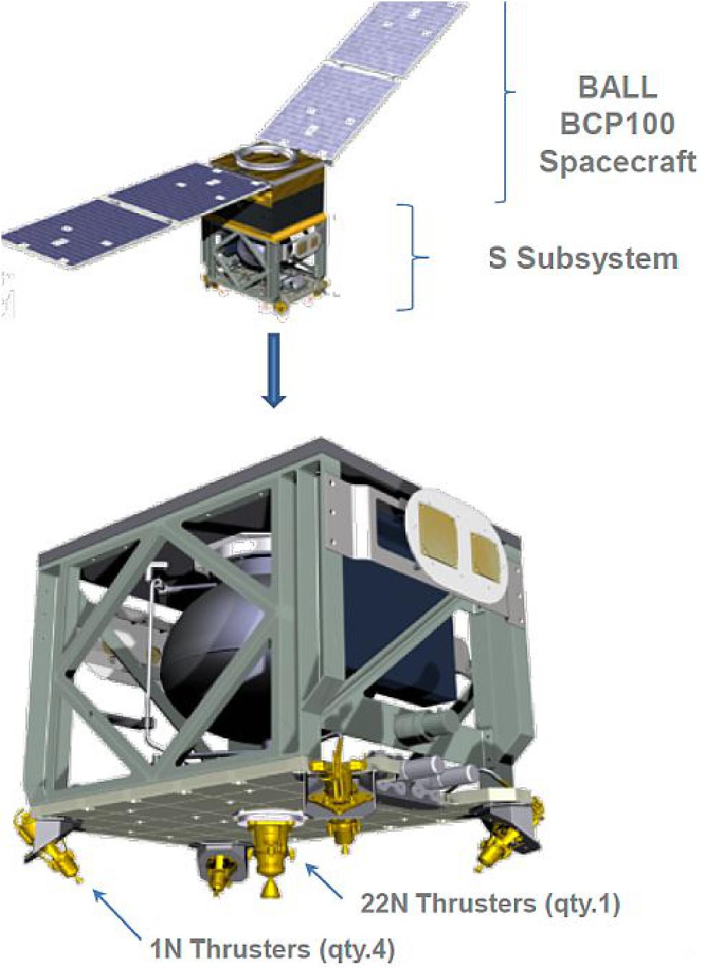
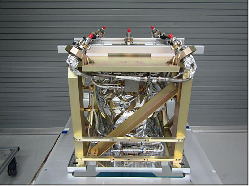
Under development as a self-contained module to allow independent assembly at Aerojet Rocketdyne for high-level integration with the BCP-100 bus, the GPIM demonstration payload configuration, illustrated in Figure 6, bears high similarity to a traditional hydrazine system. Designed to integrate with the host spacecraft via its standard PIP (Payload Interface Plate), the GPIM demonstration payload comprises a simple, single-string, blow-down AF-M315E advanced green monopropellant propulsion system employing five Aerojet Rocketdyne GR-1 1-N class thrusters, configured as a single primary divert thruster centered on an upper deck topping the payload’s box-like primary structure flanked by four attitude-control thrusters mounted one each at the adjacent corners. (Whereas both 20 N and 1 N thrusters have been developed on the program for intended respective use for divert and attitude control; in response to delays in flight-readiness of the larger thruster, 1 N thrusters will be installed at all locations.)
Because the AF-M315E propellant exhibits good compatibility with standard 6Al-4V titanium, propellant feed system components were able to be selected from a subset of heritage hydrazine system components that are compatible with little or no modification. (AF-M315E is not compatible with iron-bearing metals for long-duration storage.) Likewise, the GPIM demonstration payload module employs a conventional ATK model 80581 hydrazine propellant tank positioned near its center, all materials of construction of which have been successfully verified in thermally accelerated aging tests to be compatible with AF-M315E for durations of up to at least two years.
Aside from the 50% increased impulse delivered at comparable system volume, mission design-related distinctions between the GPIM and a traditional hydrazine system relate principally to differences in the thermal characteristics of AF-M315E vs. conventional thrusters. Due to the advanced monopropellant thrusters’ elevated minimum start temperature, catalyst bed preheat power requirements are higher than a typical hydrazine system. This increase is partially offset, however, by savings associated with the thrusters’ single (instead of conventional dual) seat valves, as well as much reduced required power for system thermal management during non-operating periods facilitated by the propellant’s demonstrated storability at very low temperatures. Radiation and conduction from the advanced monopropellant thrusters’ high temperature chambers also impart a moderate increase in the thermal load to the system mounting interface.
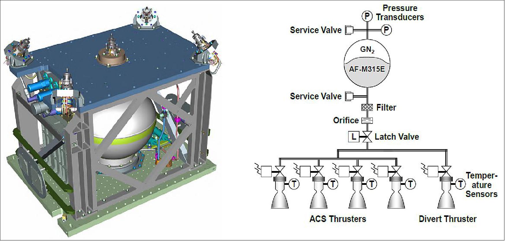
The thrusters are mounted on the upper deck of a box-like payload primary structure. The 22 N primary divert thruster is mounted on the spacecraft centerline with the thrust axis pointed through the PIP (Payload Interface Plate)-mounted propellant tank and spacecraft centers of mass. The four 1 N thrusters are canted on brackets at the corners of the upper deck to maximize the moment arm to the spacecraft center of mass, and thereby control authority and resolution of impulse measurement by the bus AODC (Attitude and Orbit Determination and Control) sensors. The remaining propulsion system components are consolidated on a component panel attached to the underside of the upper deck, except for the two service valves, which mount to a separate bracket positioned for easy access during fueling and range operations.
The design considerations for the AF-M315E propulsion system are mostly similar to a traditional hydrazine system, with a few special considerations. Principally, all system components must be compatible with AF-M315E, and therefore system component selections must strongly take compatibility into account, especially for longer duration missions. As the general schematic layout is identical to single string blow-down hydrazine systems commonly employed on small spacecraft, many of the same general design guidelines apply. The AF-M315E system however, is far less hazardous than a traditional hydrazine system when considering range safety requirements. The propellant is far less prone to leakage (due to higher viscosity), is non-toxic if leaked, and the thrusters cannot inadvertently fire without having first preheated catalyst beds. Initial discussions with KSC range safety personnel have consequently indicated the likely eventual acceptance of a reduced hazard severity classification of “critical” and possibly even “marginal” per MIL-STD-882E (Standard Practice for System Safety).
Other differentiating design considerations arise principally from differences in the thermal characteristics of AF-M315E vs. conventional thrusters. Due to the advanced monopropellant thrusters’ elevated minimum start temperature, catalyst bed preheat power requirements are higher compared to a conventional hydrazine system. This increase is partially offset, however, by the reduced power needs of the thrusters’ single seat valves, as well as much lower power required for system thermal management during non-operating periods enabled by the propellant’s demonstrated storage stability very low temperatures (although current CONOPS for the GPIM mission call for the propellant to be maintained within nominal system operating range). Radiation and conduction from the advanced monopropellant thrusters’ high temperature chambers also impart a moderate increase in the thermal load to the system mounting interface.
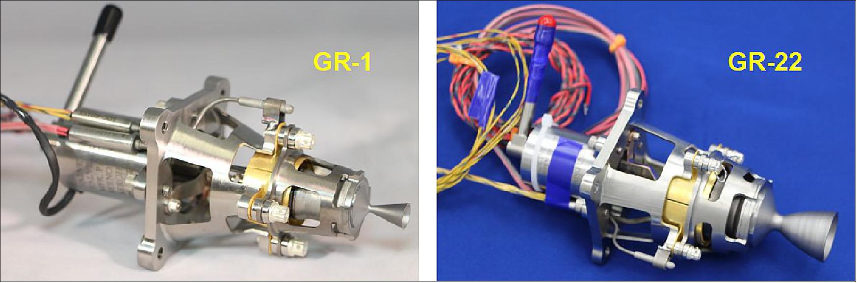
Aerojet Rocketdyne refers to the two thrusters as GR-1 (for the 1 N) and GR-22 (for the 22 N thruster) as shown is Figure 7. The advanced monopropellant thrusters to be employed on GPIM represent the culmination of over two decades of research, spanning the development of enabling high-temperature test and data acquisition techniques applied to testing of a number of candidate propellants, extensive evaluation and test of numerous material systems for structural components and catalysts, and thruster performance characterization ranging from less than 1 None up to 670 N of thrust in both sea-level and vacuum environments. Throughout a large portion of over two decades of research, inherently high reaction temperatures associated with ionic liquid propellants, coupled with poorly understood ionic-liquid thruster stability dynamics, constrained both thruster life and operational duty cycle capabilities.
The last several years, however, have yielded significant breakthroughs related to both materials and a fundamental understanding of the governing mechanics of ionic liquid thrusters necessary to design and fabricate robust, practical (duty-cycle-unlimited) thrusters with sufficient life capability to meet real mission needs. A key, albeit by no means exclusive, contributor to the rapid acceleration in maturation of AF-M315E thruster technology seen in recent times has been the advent of Aerojet’s patent-pending LCH-240 high-temperature long-life catalyst, demonstrating sufficient endurance within the propellant’s decomposition/combustion environment to extend thruster life over 15 x compared to the prior state-of-the-art.
The GR-1 and GR-22 advanced monopropellant thrusters implement a common design strategy whereby the use of refractory alloys (to accommodate the flame temperature of the AF-M315E propellant) is confined to the thrust chamber, nozzle and an upper thermal isolation structure, such that much of the thruster can be fabricated with conventional alloys in common use on hydrazine thrusters today. Trade studies indicate this hybrid approach yields significant respective cost and power savings compared to evaluated alternatives entailing either all-refractory or bulkier, heavily-insulated conventional alloy construction.
Parameter | GR-1 | GR-22 |
Nozzle expansion ratio | 100:1 | 100:1 |
Valve power @ 28VDC, 10ºC | 12 W | 28 W |
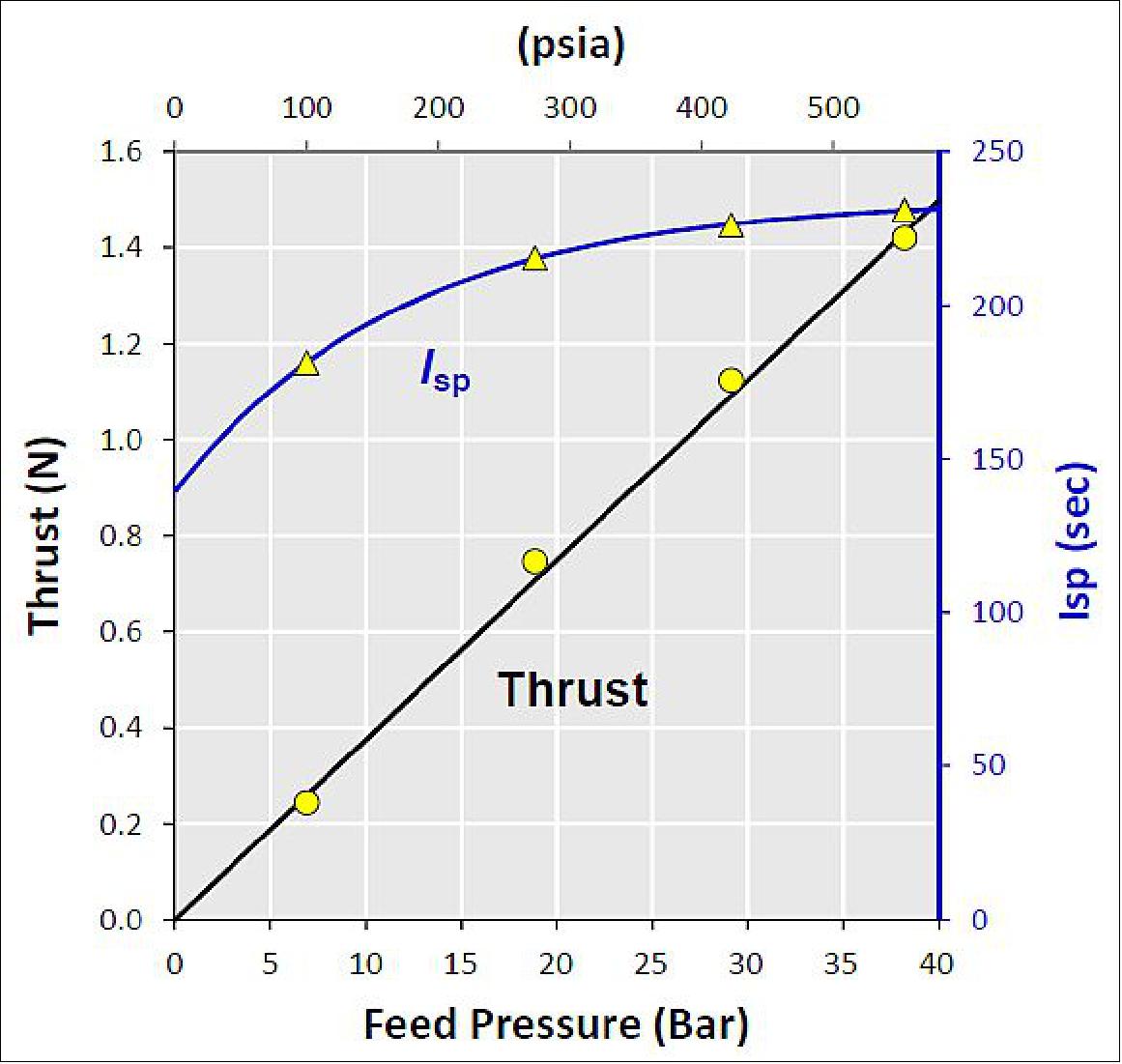
Thrust | 1.42-0.26 N | 26.9-5.7 N |
Maximum steady-state Isp | 231 s | 248 s |
Total pulses | 11,107 | 944 |
Estimated max propellant throughput capability (*) | 12 kg | 15 kg |
Prototype test propellant throughput | 4.47 kg | 3.0 kg |
Prototype test longest burn | 20 minutes | 1 minute |
Prototype test shortest commanded pulse width | 20 ms | 20 ms |
Legend to Table 2: (*) Based on heavyweight thruster life testing conducted entirely at high thrust; longer life projected for thruster operated in blow-down mode.
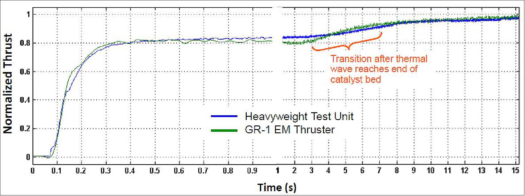
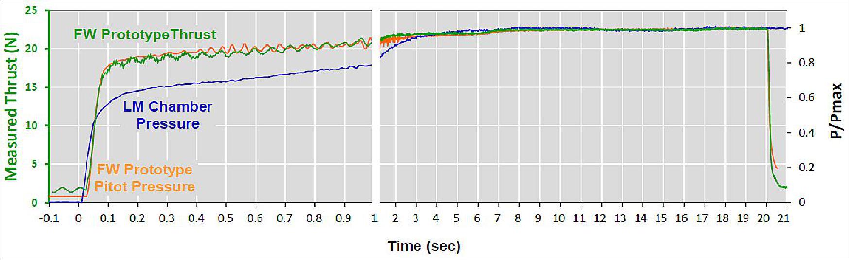
GR-1 Prototype Test Performance: Normalized start-up transient thrust profiles for the prototype GR-1 (per direct measurement) vs. its heavyweight antecedent (as computed from thrust chamber measurements) are superimposed for comparison in Figure 8. The illustrated high degree of similarity demonstrated between the two test units confirms that the insulation scheme employed in the heavyweight unit provides sufficient thermal isolation of the thrust chamber such that heat dissipation to the walls is minimal, indicating all performance metrics previously established by heavyweight testing can be expected to carry forward for flight thrusters.
The measured thrust and Isp are plotted vs. feed pressure in Figure 9. Curve fits to the data suitable for use in engineering performance predictions.
GR-22 prototype test performance: The prototype GR-22 start-up thrust and plume pitot probe recovery pressure traces are superimposed with chamber pressure data taken during prior representative heavyweight thruster testing in Figure 10. For consistency, cases where the two thrusters were operated at similar thrust level and started from similar catalyst bed preheat temperature were selected for comparison. While remaining qualitatively similar, the two sets show greater differentiation than was observed for the 1 N thruster, suggesting greater relative differences in heat transfer characteristics between the two test units. Most readily notable is the rollover of the heavyweight thruster pressure trace from the initial rapid start-up transient at ~30% lower pressure, with the subsequent rise evidencing a heat-up time-constant approximately two times that of the flight-mass prototype.
Propellant tank: The propellant tank maturation approach is designed to maximize future mission infusion potential by emphasizing proven components and processes, while focusing only upon those areas required to achieve the GPIM goals to minimize cost and schedule risk. The program has shown that the shell material of the selected tank has long-term compatibility with AF-M315E. Recent compatibility testing of the bladder material has like-wise shown acceptable performance for multi-year missions, and hence made a wide variety of existing tanks applicable for the GPIM demonstration and future missions. This revelation is a major benefit for the infusion of the technology as it enables the use of simpler and lower cost elastomeric diaphragm tanks instead of more complex PMD (Propellant Management Device) style tanks or metal diaphragm tanks. A PMD tank approach is possible for longer duration missions, however it would require an updated design, analysis and delta-qualification of the PMD for use with AF-M315E. Even with hydrazine, a PMD design usually has to be re-analyzed for each mission application, whereas a positive expulsion diaphragm provides a more robust and less sensitive propellant expulsion approach.
Thruster Development Status
• In summary, the combined high impulse density and inherent handling simplicity of advanced green monopropellants such as AF-M315E are particularly advantageous for smallsats. As such, it is no coincidence that the first on-orbit demonstration of an AF-M315E propulsion system, the capstone of NASA’s four-year GPIM program, will be aboard an ESPA-class spacecraft. With respect specifically to the engineering of smallsat systems, the GPIM program represents more than a demonstration, but validation of a flight-proven, high-performance (50% greater ρIsp than hydrazine) complete propulsion solution, ready for deployment on future missions. Intended to bracket the broadest range of thrust levels applicable to smallsats, both 1 N and 20 N class thrusters have respectively been developed to flight-ready and near-flight-ready states (Ref. 23).
- Because an additional test iteration will be necessary to fully retire flight risk for the 20-N class GR-22 thruster, but cannot be concluded within the remaining time available, the GPIM demonstration will continue on the present schedule using exclusively 1 N class GR-1 thrusters. In parallel, already-complete design updates to the GR-22 will be verified by test later in 2015, when the APTL facility becomes available following completion of ongoing hot-fire acceptance testing of the GPIM flight hardware. The GPIM propulsion module is slated for delivery for integration with the spacecraft bus in late August 2015 and subsequent launch as a secondary payload aboard the second flight of the Falcon Heavy launch vehicle in 2016.
• 1N thruster: Successfully completed the life testing that exceeded mission duty cycle requirements (Ref. 24).
• 22 N thruster: In Aug. 2014, the acceptance test procedure of hot-fire and vibration testing was completed. Significant progress on 22N testing.
According to Jonathan Overly of Aerojet Rocketdyne, the company’s work has helped to make the GPIM mission possible in many ways, particularly in increasing the life and the performance capability of the thrusters.
As the prime contractor and principal investigator, Ball collaborates with a team of co-investigators from Aerojet Rocketdyne, NASA/GRC (Glenn Research Center), NASA/GSFC ( Goddard Space Flight Center), NASA/KSC (Kennedy Space Center) and the U.S. Air Force Research Laboratory at Edwards Air Force Base, with additional mission support from the U.S. Air Force Space and Missile Systems Center at Kirtland Air Force Base on the GPIM project.
The GPIM demonstration mission will last approximately two months. Planned on-obit maneuvers include attitude control demonstrations; spacecraft pointing and hold; thruster performance characterization and mapping; inclination change; and orbit lowering. - The project is intended to bring AF-M315E and compatible tanks, valves and thrusters to an operational level for future NASA and commercial spaceflight missions (Ref. 1).
GPIM Thruster Test Campaign at GRC
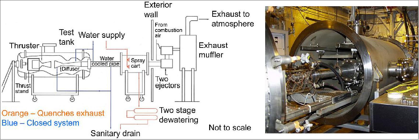
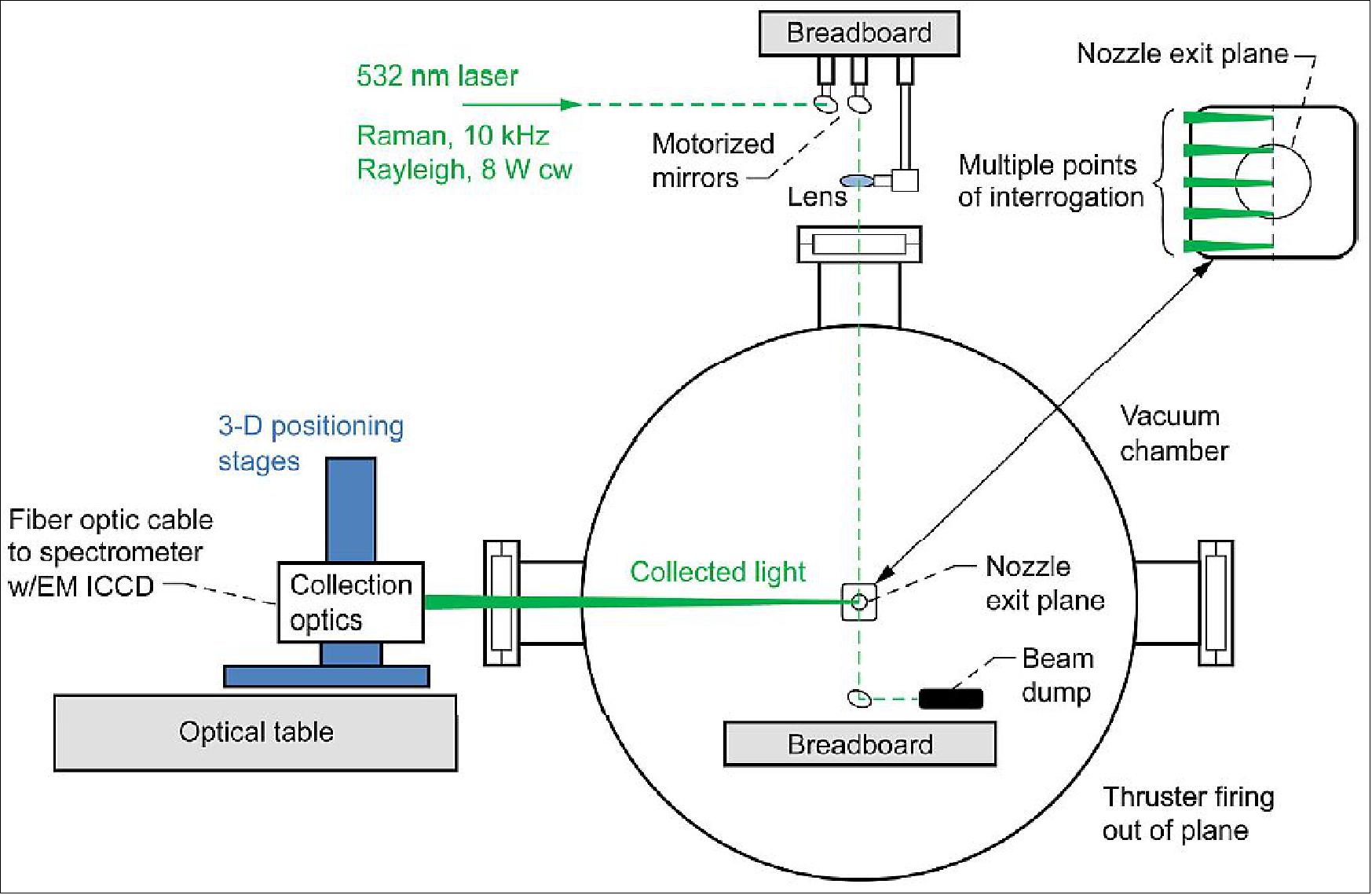
Plume measurements of an AF-M315E thruster were conducted at the GRC (Glenn Research Center) Research Combustion Laboratory – Cell 11 (RCL-11). RCL- 11 is a small rocket (<220 N), altitude (36.6 km) facility designed with optical access to incorporate the use of laser-based diagnostics. The facility uses a 1.8 m long, 0.9 m diameter cylindrical vacuum tank. The vacuum tank has four viewports, three located in a plane perpendicular to the thruster axis and the other at a 60º angle with the thruster axis with views towards the throat. Thrust is measured via load cells. Vacuum is achieved by the use of a two-stage ejector system driven by motive air supplied from a central GRC facility. The thruster is fired horizontally into a water-cooled diffuser, which provides an additional pumping effect for the vacuum tank. The water cooling system has a two stage dewatering subsystem to maintain the altitude condition of the vacuum tank throughout operation (Figure 12). RCL-11 has been used to test thrusters for up to 1 hour in duration, with the test duration limited by the thruster rather than the vacuum capability. 25)
In order to accommodate the testing of AF-M315E the issues of storage, flow system, handling, and disposal were addressed. Storage of the propellant was located adjacent to the facility. When defining specifications for the magazine, accommodations for a variety of new propellants other than AF-M315E were also considered. An ATF Type II magazine was selected. The climate control, comprised of a heater and blower, was specified so as to accommodate AF-M315E as well as potential propellants that require more stringent control such as of LMP-103S and other energetic ionic liquids. Handling and disposal considerations have been established for this propellant.
Thruster testing: A laboratory model 22 N thruster was provided by Aerojet-Rocketdyne for testing at NASA/GRC. The lab-model thruster incorporated a conical 8:1 nozzle with an exit pressure on the order of a few psia. This under-expanded condition in the RCL-chamber provided a target environment with identical plume constituents at 10 x the pressure of the more flight-like expansion of a higher-fidelity thruster which has a pressure-matched nozzle.
The thruster was typically operated in one of two modes during this test campaign. A pulse train of ten 0.5 s pulses began and ended each test day as a thruster health check. The vast majority of the remainder of the segments were continuous 4 s firings with a few longer and a few shorter included to investigate specific trends. Chamber pressure and temperature measured downstream of the catalyst bed were recorded for each operating point as function of time at a rate of 4 Hz. This allowed spectroscopic and operational data to be correlated at several points during a firing segment The test environment in the ejector driven RCL-11 operated with a base pressure around 1720 Pa (0.25 psia) at quiescent conditions, and was seen to drop to 690 Pa during thruster firing. The chamber backpressure was primarily nitrogen gas, which was being used as a purge gas to cool the thruster injector between firings. The thruster was fired into a water-cooled diffuser with an inlet inner diameter of 8.26 cm that was located approximately 6.35 cm downstream of the thruster exit plane.
A total of more than 85 successful firings with an accumulated firing time of over 6.0 minutes were completed with the LM thruster at GRC. Firings occurred with duration pulses of up to 8.0 sec and pulse trains with pulses on the order of 500 ms. The thruster has been tested through much of the GPIM regime with chamber pressures ranging from approximately 700,000-2,100,000 Pa.
In summary, the simulation and experimental work conducted through GPIM at NASA/GRC are technology risk reduction and infusion aiding tasks so that this advanced propellant may be applied in other missions. This testing, the first firing of these GPIM thrusters at a NASA center, provided valuable information correlating plume simulation models to the experimental work. These validated and anchored models will provide guidance for not only GPIM but for the future implementation of the AF-M315E green monopropellant in enhancing future spacecraft.
iMESA-R (Integrated Miniaturized Electrostatic Analyzer Reflight)
iMESA-R is a USAFA (U.S. Air Force Academy) mission designed to measure plasma densities and temperatures. The iMESA-R is a space weather constellation, consisting of four inexpensive space weather instruments. The DoD STP (Space Test Program) is providing flights for iMESA-R on four different spacecraft. These are: 26)
• GPIM (Green Propellant Infusion Mission) — FY16
• OTB (Orbital Test Bed) — FY16
• STPSat-4 — FY-17
• STPSat-5 — TBD
• Each iMESA-R instrument provides two measurements:
- Low energy plasma (Electrostatic Analyzer)*
- Radiation (Dosimeter)
The objective of the iMESA-R measurements are:
- Operators need to quickly distinguish between environmentally induced and possible hostile anomalies
- iMESA-R concentrates on ionosphere and ionizing radiation
- Ionosphere: Plasma irregularities (“bubbles”) cause scintillation. The results are: a) Loss of GPS lock (50% availability during severe scintillation); b) Loss of SATCOM (i.e., communication).
- Radiation: Single event upset, dose effects, deep dielectric charging
- Forecasting is a priority — requires NowCast
- NowCast requires multipoint measurements
- iMESA-R provides a 4 satellite constellation.
Heritage and Future:
• The iMESA technology is patented by USAFA. The development was funded by AFOSR (Air Force Office of Scientific Research) and AFRL.
• IMESA launched on:
- MISSE-7(ISS), iMESA 2009-2011 = 1st data collection
- STP-H4 MESA launched in Aug. 2013 = 1st reflight
- STPSat-3 iMESA launch Nov. 2013 = 2nd reflight.
• Mature hardware, software, electronics. Demonstrated success on three missions.
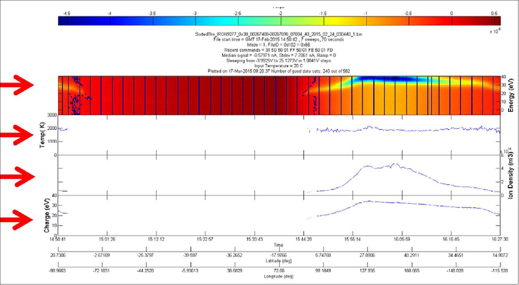
Legend to Figure 15: (top panel is equivalent to first red arrow from top)
1) Top panel: raw data product: energy-time spectrogram
• Density increases in sunlight
• Energy increases in sunlight
2) 2nd panel down: Ion temperature
3) 3rd panel down: Ion density
4) Bottom panel: derived spacecraft charging.
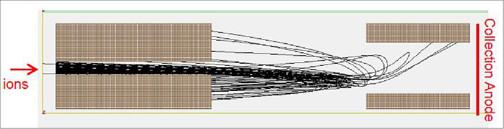
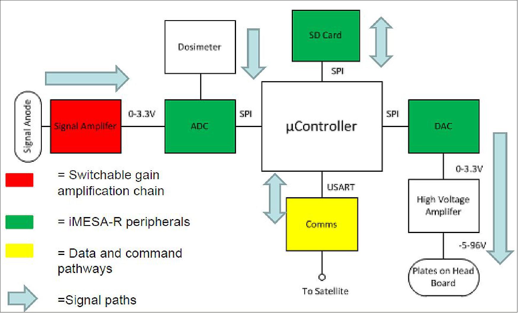
Changes for iMESA-R Flights (GPIM, OTB, STPSat-4 and STPSat-5)
• New electrostatic analyzer (ESA) design.
- Improved temperature measurements
- Reduces number of plates—ease of manufacture
• Switchable range on ESA
- Allows for different host S/C charging
• Programmable gain amplifier
- Assures data collection during entire orbit
- Higher transimpedance amplifier gain
• New power supply design
- Reduces EMI
- Change of one power supply allows flights on many different satellites
• Added dosimeter
- Allows ionizing radiation monitoring
• Rewritten software
- Assures modularity and future upgrades.
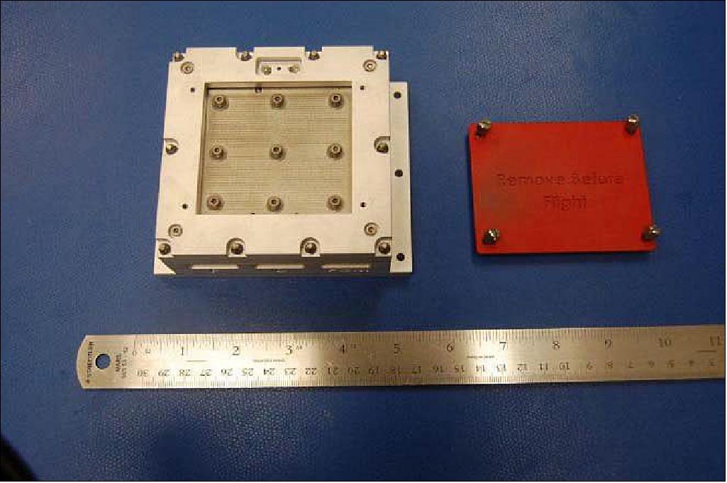
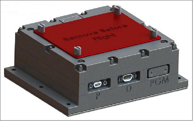
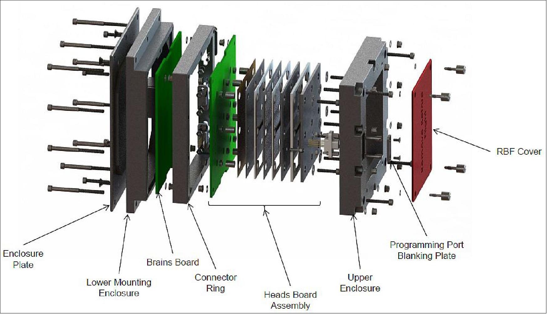
iMESA-R Instrument
• Fits into a 45 mm x 102 mm x 126 mm envelope (without RBF Cover)
• Mass is ~1kg (including mounting hardware)
• Al 6061-T651 per ASTM-B209
• PCBs (Printed Circuit Boards) are enclosed within the assembly
• Designed to fit PC-104 boards
- Keying features on boards
- Easy integration into CubeSats (for future missions)
• Modular structure design to be barnacle mount or panel flush mount
SWATS (Small Wind and Temperature Spectrometer)
SWATS is a NRL (Naval Research Laboratory) mission to provide in-situ, co-located measurements of the atmospheric neutral and ion density, composition, temperature, and winds on a global scale. These data will support improvements to the thermospheric/ionospheric density and wind models to improve orbit determination and prediction.
The SWATS instrument siute is capable of measuring neutral winds, neutral temperature, neutral composition, ion drifts, ion temperature, and ion composition.
SOS (Space Object Self-tracker)
SOS is a pathfinder experiment built by the U.S. Air Force Institute of Technology (AFIT) to decrease space collisions. 27)
References
1) “Green Propellant Infusion Mission Project - New green fuel technology will enable safer, faster and less costly space missions,” NASAFacts, URL: http://www.nasa.gov/sites
/default/files/files/Green-Propellant-Infusion-Mission-Project_-Fact-Sheet.pdf
2) “Green Propellant Infusion Mission Project,” NASA Fact Sheet, URL: http://www.nasa.gov/sites/default/files/files/Green-Propellant-Infusion-Mission-Project_-Fact-Sheet.pdf
3) “Green Propellant Infusion Mission (GPIM),” NASA, Jan. 16, 2015, URL: http://www.nasa.gov/mission_pages/tdm/green/gpim_overview.html#.VTi-q5M_P_U
4) Doug Messier, “NASA’s Green Propellant Infusion Mission to Test Advanced Thermal Insulation,” Parabolic Arc, Oct. 29, 2013, URL: http://www.parabolicarc.com/2013/10
/29/nasa-green-propellant-infusion-mission-test-advanced-thermal-insulation/
5) “Green Propellant Infusion Mission (GPIM),” BATC, URL: http://www.ballaerospace.com
/page.jsp?page=281
6) ”Ball Aerospace's Green Smallsat Ready for NASA's Green Propellant Mission Arrives in Florida,” Satnews Daily, 21 May 2019, URL: http://www.satnews.com/story.php?number=1620893901
7) Kim Newton, ”NASA Spacecraft to Test 'Green' Propellant Passes Major Pre-flight Milestone,” NASA, March 31, 2016, URL: http://www.nasa.gov/mission_pages
/tdm/green/green-propellant-test-passes-preflight-milestone.html
8) Kim Newton ”Green Propellant Infusion Mission Passes Spacecraft Integration Milestone, On Track for 2016 Launch,” NASA/MSFC, Oct. 5, 2015, URL: http://www.nasa.gov/mission_pages/tdm/green
/green-propellant-infusion-mission-passes-spacecraft-integration-milestone-on-track-for-2016.html
9) Kim Newton, ”Green Propellant Infusion Mission Receives Propulsion System; On Track for 2016 Launch,” NASA/MSFC, Aug. 28, 2015, URL: http://www.nasa.gov/mission_pages
/tdm/green-propellant-infusion-mission-receives-propulsion-system.html
10) Rick Smith, “Green Propellant Team Propels Itself Through Preliminary Design Review,” NASA, Sept. 20, 2013, URL: http://www.nasa.gov/mission_pages
/tdm/green/green-propellant-preliminary-review.html#.VRlk9eHuz_V
11) Stephen Clark, ”Falcon Heavy launches on military-led rideshare mission, boat catches fairing,” Spaceflight Now, 25 June 2019, URL: https://spaceflightnow.com/2019/06/25
/falcon-heavy-launches-on-military-led-rideshare-mission-boat-catches-fairing/
12) ”NASA Technology Missions Launch on SpaceX Falcon Heavy,” NASA Release 19-049, 25 June 2019, URL: https://www.nasa.gov/press-release/nasa-technology-missions-launch-on-spacex-falcon-heavy
13) “GPIM Spacecraft to Validate Use of 'Green' Propellant,” NASA, Aug. 19, 2014, URL: http://www.nasa.gov/content/gpim-spacecraft-to-validate-use-of-green-propellant/
14) ”NASA Technology Missions Launch on SpaceX Falcon Heavy,” NASA Release 19-049, 25 June 2019, URL: https://www.nasa.gov/press-release/nasa-technology-missions-launch-on-spacex-falcon-heavy/
15) Ball Aerospace Completes Successful Smallsat, Green Fuel Mission,” Satnews, 20 August 2020, URL: https://news.satnews.com/2020/08/20
/ball-aerospace-completes-successful-smallsat-green-fuel-mission/
16) ”Brian Marotta, Christopher McLean, Brad Porter, ”On-Orbit Performance of the BCP-100 Green Propellant Infusion Mission,” Proceedings of the 34rd Annual AIAA/USU Virtual Conference on Small Satellites, August 1-6, 2020, Logan, UT, USA, paper: SSC20-II-03, URL: https://digitalcommons.usu.edu/cgi/viewcontent.cgi?article=4715&context=smallsat
17) ”Ball Aerospace Successfully Commissions Small Satellite, Begins On-Orbit Testing of Green Fuel,” Ball News Release, 5 July 2019, URL: http://ball.mediaroom.com/2019-07-05-Ball-Aerospace-
Successfully-Commissions-Small-Satellite-Begins-On-Orbit-Testing-of-Green-Fuel?asPDF=1
18) “Ball Aerospace Green Propellant Infusion Mission to Host Three Defense Department Space Experiments,” BATC, Oct. 15, 2014, URL: http://www.ballaerospace.com/page.jsp?page=30&id=610
19) Ronald A. Spores, Robert Masse, Scott Kimbrel, “GPIM AF-M335E Propulsion System” Proceedings of the 49th AIAA/ASME/SAE/ASEE Joint Propulsion Conference &Exhibit, San Jose, CA, July 15-17, 2013, URL: https://www.rocket.com/files/aerojet/documents/Capabilities
/PDFs/GPIM%20AF-M315E%20Propulsion%20System.pdf
20) W. Deininger, B. Porter, A. Sexton, V. Moler, B. Marotta, R. Osborne, M. Riesco, R. Wendland, D. Acton, C. McLean, M. Tshudy, P. Aggarwal, ”Incorporation of secondary payloads onto the Green Propellant Infusion Mission (GPIM),” IEEE Aerospace Conference, Big Sky, MT, USA, March 7-14, 2015
21) “GPIM Spacecraft to Validate Use of “Green” Propellant,” NASA, August 19, 2014, URL: http://www.nasa.gov/content/gpim-spacecraft-to-validate-use-of-green-propellant/
22) Ronald A. Spores, Robert Masse, Scott Kimbrel, Chris McLean, “GPIM AF-M315E Propulsion System,” 49th AIAA/ASME/SAE/ASEE Joint Propulsion Conference &Exhibit,San Jose, CA, USA, July 15-17, 2023, paper: AIAA 2013-3849, URL: https://www.rocket.com/files/aerojet
/documents/Capabilities/PDFs/GPIM%20AF-M315E%20Propulsion%20System.pdf
23) Robert K. Masse, Ronald A. Spores, May Allen, Scott Kimbrel, Chris McLean, ”Enabling High Performance Green Propulsion for SmallSats,” Proceedings of the 29th Annual AIAA/USU Conference on Small Satellites, Logan, Utah, USA, August 8-13, 2015, paper: SSC15-XI-6, URL: http://digitalcommons.usu.edu/cgi/viewcontent.cgi?article=3240&context=smallsat
24) Timothy Chen, “Technology Demonstration Missions Program -Green Propellant Infusion Mission- Ball,” NASA, Dec. 4, 2014, URL: http://www.nasa.gov/sites/default/files/files/TChen_TDM.pdf
25) Timothy D. Smith, Mattew C. Deans, John T. Yim, George J. Williams, Jun J. Kojima, Christopher McLean, ”Overview of NASA’s Green Propellant Infusion Mission and NASA Glenn Research Center’s Thruster Testing and Plume Diagnostics,” IAC-15-C4.4.3.5
26) Parris Neal, Alex Strom, Nikolas Taormina, “IMESA-R Integrated Miniaturized Electrostatic Analyzer – Reflight,” 31st Space Symposium, Colorado Springs, CO, USA, April 13-16, 2015, URL of paper: http://www.spacesymposium.org/sites/default/files/downloads
/P.Neal_31st_Space_Symposium_Tech_Track_paper.pdf, URL of presentation: http://www.spacesymposium.org/sites/default/files/downloads
/P.Neal_31st_Space_Symposium_Tech_Track_Presentation.pdf
27) Megan Shaffer, “Space Object Self-Tracker Experiments,” 39th AIAA Annual Dayton-Cincinnati Aerospace Sciences Symposium, Dayton, Ohio, March 5, 2014, paper: 39DCASS‐109
The information compiled and edited in this article was provided by Herbert J. Kramer from his documentation of: ”Observation of the Earth and Its Environment: Survey of Missions and Sensors” (Springer Verlag) as well as many other sources after the publication of the 4th edition in 2002. - Comments and corrections to this article are always welcome for further updates (eoportal@symbios.space).
Spacecraft Launch Mission Status Sensor Complement References Back to top