GP-B (Gravity Probe B)
EO
NASA
Mission complete
Gravity and Magnetic Fields
Quick facts
Overview
| Mission type | EO |
| Agency | NASA |
| Mission status | Mission complete |
| Launch date | 20 Apr 2004 |
| End of life date | 08 Dec 2010 |
| Measurement domain | Gravity and Magnetic Fields |
| Measurement category | Gravity, Magnetic and Geodynamic measurements |
| Measurement detailed | Gravity field, Gravity gradients |
| Instruments | GPS receiver |
| Instrument type | Data collection, Gravity instruments |
| CEOS EO Handbook | See GP-B (Gravity Probe B) summary |
GP-B (Gravity Probe B)
Overview Spacecraft Launch Mission Status Experiment Payload (SIA) References
GP-B is a NASA fundamental gravitational physics mission, developed at Stanford University (PI: C. W. F. Everitt), Stanford, CA. Stanford developed and built the experiment apparatus consisting of the gyroscopes, the quartz block, the SQUIDs (Superconducting Quantum Interference Device) and the telescope. In the overall arrangement, Stanford University is prime contractor to NASA/MSFC (project management) with a major subcontract to LMMS (Lockheed Martin Missiles and Space) of Palo Alto, CA, consisting of the spacecraft and the payload (Dewar and Probe).
The overall objective is to provide two extremely precise new tests of Einstein's theory of gravity, namely the General Theory of Relativity (formulated in 1916 - it states that gravity affects time and distance, by stretching time and contracting distance in the presence of a gravitational field) by means of observations on gyroscopes in Earth orbit.
The GP-B experiment measures, very precisely, tiny changes in the directions of spin of four gyroscopes contained in an Earth-orbiting polar satellite. The gyroscopes will be so free of disturbances that they will provide an almost perfect space-time reference system. They will measure how space and time are warped by the presence of the Earth (as a mass-energy system), and, more profoundly, how the Earth's rotation drags space-time around with it. These effects, though small for the Earth, have far-reaching implications for the nature of matter and the structure of the Universe. Since GP-B is a "controlled physics experiment" it required many years of challenging work and sophistication in technology. The GP-B mission is expected to be approximately 16 months long. 1) 2) 3) 4) 5) 6) 7) 8) 9) 10)
Spacecraft
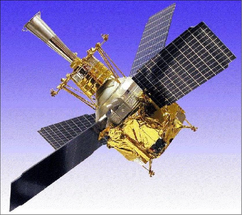
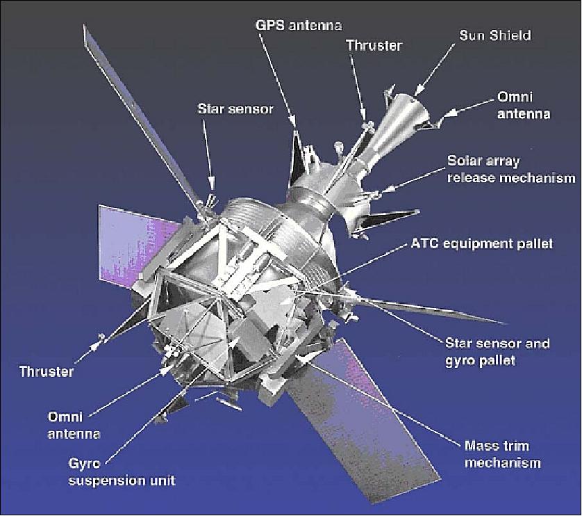
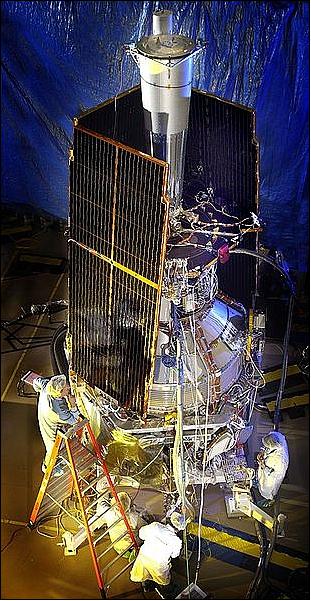
The spacecraft is spin stabilized (0.1 to 1 rpm) using proportional helium thrusters (drag-free control). Attitude measurements are provided with a cryogenic science telescope and control gyros for angular rates. The attitude reference platforms are mounted on the stable graphite rings of the dewar. Each platform has a star tracker and a rate gyro providing the information to orient the S/C initially to acquire the guide star (IM Pegasi, HR8703) with the science telescope, and to maintain accurate pointing during 45 minutes of occultation of the guide star by the Earth during each orbit. The pointing control <20 milliarcseconds rms. An onboard GPS receiver (two fully redundant sets of a receiver and 4 antennas of Trimble Navigation Ltd.) provides tracking of GP-B. The S/C structure has a length of 6.43 m, a diameter of 2.64 m, a total mass of 3,100 kg, total power of 606 W (payload = 313 W, in addition two batteries of 35 Ah), design life = 3 years.
Star trackers: The spacecraft contains two star trackers to perform the "spotting function" for the telescope - one wide FOV (Field of View) and one narrow FOV (called the star sensor). The wide FOV star tracker is used to locate the general region of the heavens containing the guide star, and then the narrow FOV star tracker helps align the space vehicle with the guide star. - The onboard telescope basically performs the same function as the star trackers, but it uses a different technique, and it is orders of magnitude more precise and more accurate. The narrow FOV star tracker has a field of view on the order of 1º (60 arcminutes), and it can focus to a position within perhaps one arcminute - about the same as the entire FOV of the onboard telescope, which can pinpoint the guide star's position to within a milliarcsecond (in fact 0.1 marcsec).
The S/C has an on-board solid-state recorder of 1.9 Gbit capacity. There are two communication links, a direct downlink via S-band at 2.5 Mbit/s, and a TDRS MA (Multiple Access) link at 1.032 kbit/s (return) and 250 bit/s (forward). The GP-B mission is being operated from Stanford University.
Launch
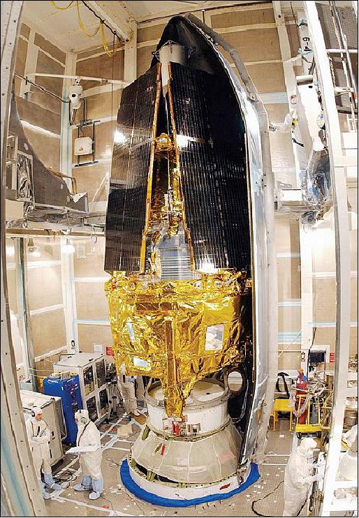
A successful launch of GP-B took place on April 20, 2004 on a Delta-2 (model 7920-10) vehicle from VAFB, CA. A first check-out of the spacecraft after launch and deployment was very positive.
Orbit: An exact polar orbit (near-circular), average altitude of 642 km, inclination of 90º, period of 97.5 minutes, eccentricity e = 0.0014, the orbital plane is aligned with the guide star direction. The ideal gravitational orbit, exactly over the Earth's poles, at relatively low altitude with GPS tracking, makes GP-B an exceptionally sensitive instrument for exploring the fine structure of the Earth's gravitational field.
In-orbit checkout and calibration phase is scheduled to last 40-60 days, followed by a 13 month science data acquisition period and a two month post-science period for calibrations.
Spacecraft size | 6.4 m (L) x 2.6 m (Ø) |
Spacecraft mass | 3100 kg |
Pointing accuracy | 0.2 arcsec |
Drag-free capability | 10-11 g |
Power | 606 W (total), S/C = 293 W, payload = 313 W |
Battery (2) | 35 Ah |
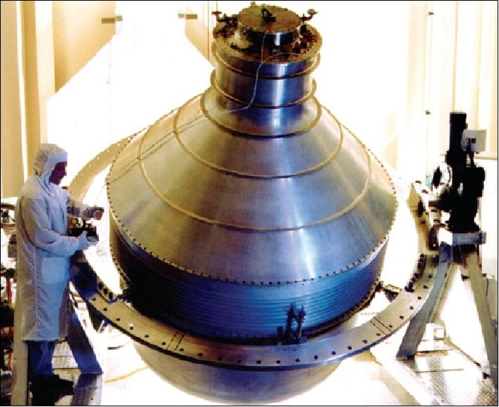
Dewar size | 2.7 m (H) x 2.6 m (Ø) |
Dewar contents | 2441 liter of superfluid helium @ 1.8 K |
Some Background on GP-B
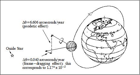
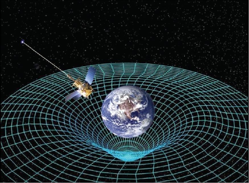
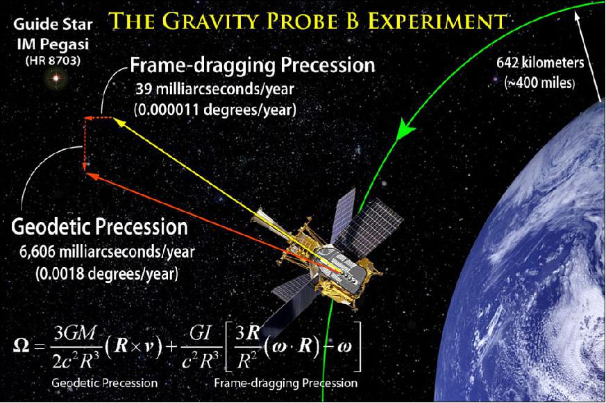
Earth is a mass-energy system. According to General Relativity, as a mass-energy, it should create a little dimple in the local space-time fabric. A gyroscope orbiting the Earth experiences two distinct space-time processes - namely the "frame-dragging" effect and the geodetic effect (orthogonal effects) - gradually changing its direction of spin. 11)
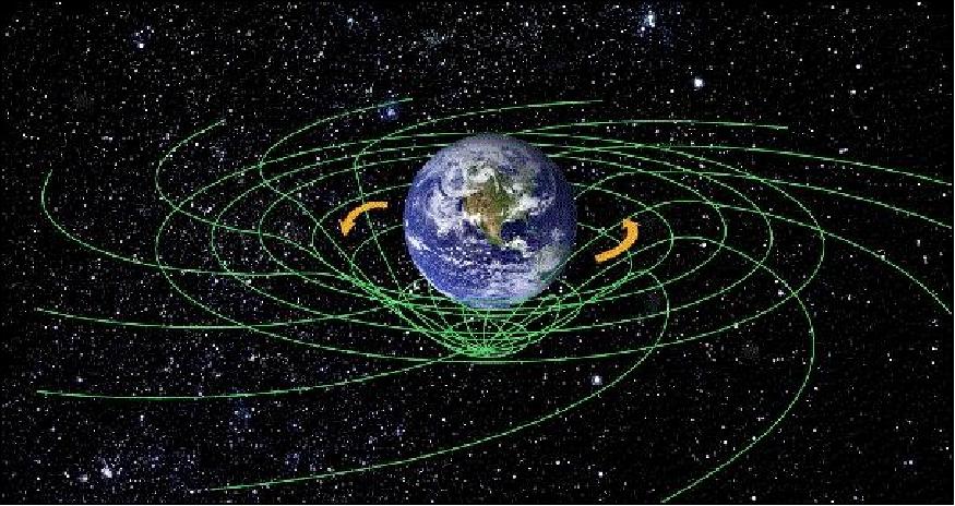
• Frame dragging (relates local physics to the rotation of the universe's mass distribution): A rotating massive body drags space and time around with it. A gyroscope orbiting Earth tends to tilt away from the plane of its orbit because the Earth is dragging it.
• Geodetic Effect: According to Einstein's General Theory of Relativity, space and time in the vicinity of a massive body is distorted. For a gyroscope orbiting near the Earth, this distortion leads to a tilting of the gyroscope's spin axis in the plane of the orbit. This effect is predicted by the general relativity theory to be 150 times larger than the frame dragging. The geodetic effect follows from the gyroscope's motion through this space-time curvature. The predicted effect for a gyroscope is a rotation in the orbit-plane of 6,600 milliarcseconds per year - quite a large angle by relativistic standards (see Figure 5). GP-B will measure this change to 1 part in 10,000 or better (0.01%).
In late 1959, these concepts were independently conceived and formulated by the physicists, Leonard Schiff of Stanford University and George W. Pugh of the US DoD (Department of Defense). According to calculations by L. Schiff, the frame-dragging effect (rotation of space-time) should turn the gyroscope with the Earth through an angle of 42 milliarcseconds in a time period of one year. G. Pugh provided a complete error analysis of a possible experiment. In particular, he suggested for the first time the far-reaching concept of a drag-free (or drag-compensated) satellite. 12) The GP-B project evolved eventually from these early thoughts.
The principle behind the Gravity Probe B measurement is that ideal rotating gyroscopes, free of disturbing forces, always point in the same direction in inertial space. In Newtonian physics, a perfect gyroscope pointed at a star should stay aligned forever. In Einstein's physics, the direction of the spin axis of the gyroscope will gradually change due to the mass and rotation of the Earth by an amount that can be exactly predicted. The gyroscopes will measure whether and how space and time are warped by the presence of Earth, and whether and how the rotating Earth drags space-time around with it.
The measurement of Schiff's two effects demands much more than placing a gyroscope in a satellite. Six distinct technical requirements have to be simultaneously satisfied:
1) A drift-free gyroscope: a gyroscope having an absolute drift-rate (i.e. change in spin direction from non-relativistic disturbances) of <10-11 degrees/hour. This is six orders of magnitude (106) better than the best inertial navigation gyros available.
2) A gyro readout: a method for determining the changes in spin angle to 0.1 milliarcsecond without disturbing the gyroscope.
3) A stable reference: a means (telescope and mechanical structure) of referring the gyro readout to the guide star.
4) A trustworthy guide star: a bright, properly located star whose motion with respect to inertial space is known.
5) A technique for separating relativity effects: an orbit and a data processing method that together allow the frame-dragging and geodetic effects to be separated.
6) A credible calibration scheme: a scheme of in-flight calibration tests to ensure that the gyroscopes - and the entire instrument - are free of errors that might masquerade as relativity signals.
All six prerequisites are met by GP-B. Every "technology component" of GP-B has been demonstrated a priori to a precision consistent with the flight requirements, some even in space.

Mechanical Systems
Two mechanical systems, essential to the success of the relativity measurement, are decidedly unusual: 13) 14) 15) 16) 17)
1) A set of seven mass-trim mechanisms is used to balance and align the principal axis of the spacecraft
2) The use of helium proportional thrusters
Mass trim mechanisms. Each mass trim mechanism consists of a 20 kg mass mounted in a closed rectangular box; they are adjusted in position by a lead screw driven by a stepper motor. These mechanisms have been subject to a very extensive qualification program. Four of the masses are mounted transversely to move the axis of rotation laterally until it coincides with the line through the center of the gyroscopes to within 0.8 mm. The other three masses are mounted parallel to the S/C axis, they adjust the direction of the principal axis of inertia. Trimming is performed intermittently as the helium is depleted (this occurs probably a few times during the course of a year).
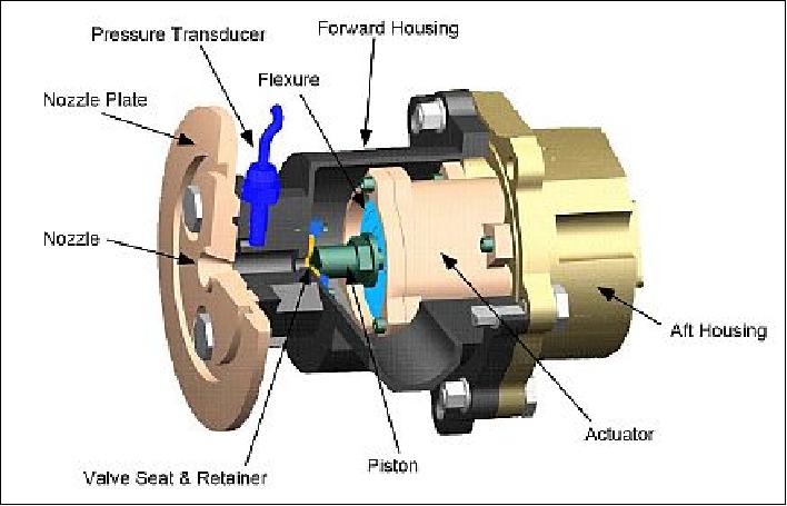
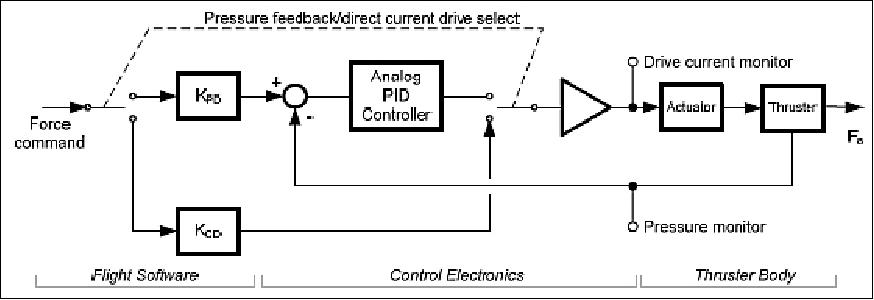
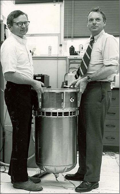
Helium proportional thrusters for attitude and translational control: In most S/C with gas-jet attitude control systems, constraints on gas consumption set by mass dictate the use of on-off valves that are fired only on demand. To apply this method to GP-B with its very fine pointing requirement of ±20 milli-arcseconds would take a space-qualified valve capable of reseating perfectly hundreds of millions of times; this is obviously a severe reliability problem. Fortunately there is a solution. Already on board is a supply of gas that must be vented, namely the helium boil-off from the dewar. By directing this gas continuously through pairs of opposed nozzles operated as "proportional thrusters," one obtains a control system that is at once smoother and mechanically more reliable than the conventional kind. This design was proposed by Stanford graduate students (J. S. Bull, J.-H. Chen, P. Wiktor and Y. Jafry) and eventually further developed and built by Lockheed Martin.
S/C control is maintained in all three support modes, namely pointing, drag-free, and roll, using signals derived from:
• The science telescope
• Either of two science gyroscopes operated drag-free
• Conventional rate-gyroscopes mounted on the spacecraft
The signals are updated from a 'star-blipper' picking up a band of stars spread over the heavens at an angle to the roll axis. The pointing accuracy is better than 10 milli-arcsec, the residual cross-track average acceleration is measured to better than 10-12 g, and the roll rate to about 1 part in 105. The translational controller is designed to force the center of rotation of the S/C into coincidence with the line through the gyro centers. The mass trim mechanism brings it within 0.8 mm; the translational controller brings it to 50 μm, that is, to within the limit to which the gyros are aligned. - The spacecraft has 16 helium thrusters mounted on fixed struts, and extending from the S/C, with geometrical and internal redundancies such that any four systems can be allowed to fail with no loss of control performance.
Note, acceleration levels on satellites at the GP-B altitude (of 640 km) with normal mass/area ratios are typically of the order of 10-8 g. In GP-B, as a drag-free spacecraft rolling about the common axis of the gyroscopes, the mean cross-track acceleration will be below 10-12 g.
Mission Status
• After launch (April 20, 2004), an IOC (In-Orbit Checkout) phase of 4.2 months followed in which all systems and instruments were initialized, tested, and optimized for the data collection to follow. The IOC phase culminated with the spin-up and initial alignment of each of the four science gyros early in August 2004.
• The science phase of the mission started on Aug. 27, 2004 and ended on Aug. 15, 2005, collecting data on the changing spin axis orientation of the four gyros that will ultimately confirm or disprove the geodetic and frame-dragging predictions that arise from Albert Einstein's General Theory of Relativity -the theory of gravity that he published in 1916. 18) 19)
• As of Sept. 29, 2005 the liquid helium in the dewar was exhausted - thus, ending the period of science data collection from the spacecraft. The very successful mission lasted for a total 17 months. With all the helium propellant used up, the micro-thruster system became inactive, and without thrusters, it is no longer possible to maintain a drag-free flight.
• Drag-free control for the GP-B satellite functioned well on orbit, giving a residual acceleration on the space vehicle of 4×10-11 m s-2 from < 0.01 mHz to 10 mHz in inertial space. In pointing, the vehicle was able to maintain a stable roll frequency of 0.081 rad/sec (13 mHz) with a roll phase error of 0.13 mrad RMS while holding pointing to within 0.97 µrad RMS (0.2 arcsec RMS) of the line of sight to the guide star.
The boil-off gas from the 2440 liter superfluid helium dewar was an effective source of propellant for the space vehicle's attitude and translation control system, always providing sufficient mass flow to control the vehicle in 6 degrees of freedom. The Lockheed Martin designed proportional helium thrusters were successful in providing reliable and accurate response to commands with a specific impulse of up to 130 s. Overall, the drag-free system reduced the gravity gradient and environmental forces on the space vehicle by a factor of ~10,000 below ambient orbit environmental conditions. This reduced to an insignificant level a primary source of torque on the gyroscopes, and thus it eliminated an important error source for the measurement of the effects of General Relativity in the GP-B experiment. 20) 21)
• During the 50-week science phase of the GP-B mission and the 7-week instrument calibration phase, which lasted from August 2004 to the end of September 2005, the project collected over 1 TByte of experimental data which have been downloaded from the spacecraft and relayed to Stanford University. Scientists have begun the painstaking task of data analysis and validation, which is expected to take approximately 1 1/2 years.
• In the fall of 2006, both the GP-B space vehicle and the payload remain in good health. The dewar inside temperature at ~ 256.6 K has essentially reached thermal equilibrium with the dewar's outer shell temperature (~254.5 K). From now on, both the inner temperature of the dewar and its outer shell temperature will continue to fluctuate slightly, due to "seasonal" changes in the spacecraft's position in relation to the sun.
• Arrangements were made with the USAFA (US Air Force Academy) of Colorado Springs, CO, to use the spacecraft part time - shared with the use at Stanford University - as a space operations training vehicle (starting in Oct. 2006).
• At the APS (American Physical Society) spring meeting in Jacksonville, FLA (April 14-17, 2007), Everitt and his team presented preliminary results of the GP-B data analysis which clearly confirm Einstein's predicted geodetic effect to a precision of better than 1 percent. However, since the frame-dragging effect is 170 times smaller than the geodetic effect, it will take to the end of 2007 for a more detailed analysis of the frame-dragging effect. 22) 23) 24)
• In Sept. 2008, the GP-B science team is continuing to make large strides in the data analysis. NASA funding and sponsorship of the program ended on September 30, 2008, but GP-B has secured alternative funding that will enable the science team to continue working at least through December 2009 to complete the data analysis and bring GP-B to a proper close. 25)
• Closing in on Einstein: Frame-Dragging Clearly Visible: The accuracy of the GP-B experimental results has improved seventeen-fold since our preliminary results announcement at the American Physical Society annual meeting in April 2007. At that time, only the larger, geodetic effect was clearly visible in the data. Over the past two and one half years, the analysis team has made extraordinary progress in understanding, modeling and removing three Newtonian sources of error—all due to patch potentials on the gyroscope rotor and housing surfaces. 26) 27)
• The GP-B spacecraft was decommissioned on December 8, 2010 (although the science data collection ended already in late September 2005).
Overview of some mission statements at the GP-B at the NASA press conference on May 4, 2011 (Referenceces: 28) 29) 30) 31) 32))
• On May 4, 2011, the research team of the GP-B (Gravity Probe-B) mission announced the long-awaited final science results at a press conference at NASA headquarters in Washington D. C. 28) 29) 31)
According to the PI of the GP-B mission, Francis Everitt of Stanford University, "The space-time around Earth appears to be distorted just as general relativity predicts."
Time and space, according to Einstein's theories of relativity, are woven together, forming a four-dimensional fabric called "space-time." The mass of Earth dimples this fabric, much like a heavy person sitting in the middle of a trampoline. Gravity, says Einstein, is simply the motion of objects following the curvaceous lines of the dimple.
GP-B determined both effects with unprecedented precision by pointing at a single star, IM Pegasi, while in a polar orbit around Earth. If gravity did not affect space and time, GP-B's gyroscopes would point in the same direction forever while in orbit. But in confirmation of Einstein's theories, the gyroscopes experienced measurable, minute changes in the direction of their spin, while Earth's gravity pulled at them (Figure 13).
The drag-free satellite concept pioneered by GP-B made a number of Earth-observing satellites possible, including the GRACE (Gravity Recovery and Climate Experiment) and the GOCE (Gravity field and steady-state Ocean Circulation Explorer) missions. These satellites provide the most precise measurements of the shape of the Earth, critical for precise navigation on land and sea, and understanding the relationship between ocean circulation and climate patterns.
GP-B is one of the longest running projects in NASA history, with agency involvement starting in the fall of 1963 with initial funding to develop a relativity gyroscope experiment. Subsequent decades of development led to groundbreaking technologies to control environmental disturbances on spacecraft, such as aerodynamic drag, magnetic fields and thermal variations. The mission's star tracker and gyroscopes were the most precise ever designed and produced.
• Summary of Final GP-B Experimental Results
After 31 years of research and development, 10 years of flight preparation, a 1.5 year flight mission and 5 years of data analysis, our GP-B team has arrived at the final experimental results for this landmark test of Einstein's 1916 general theory of relativity. 33)
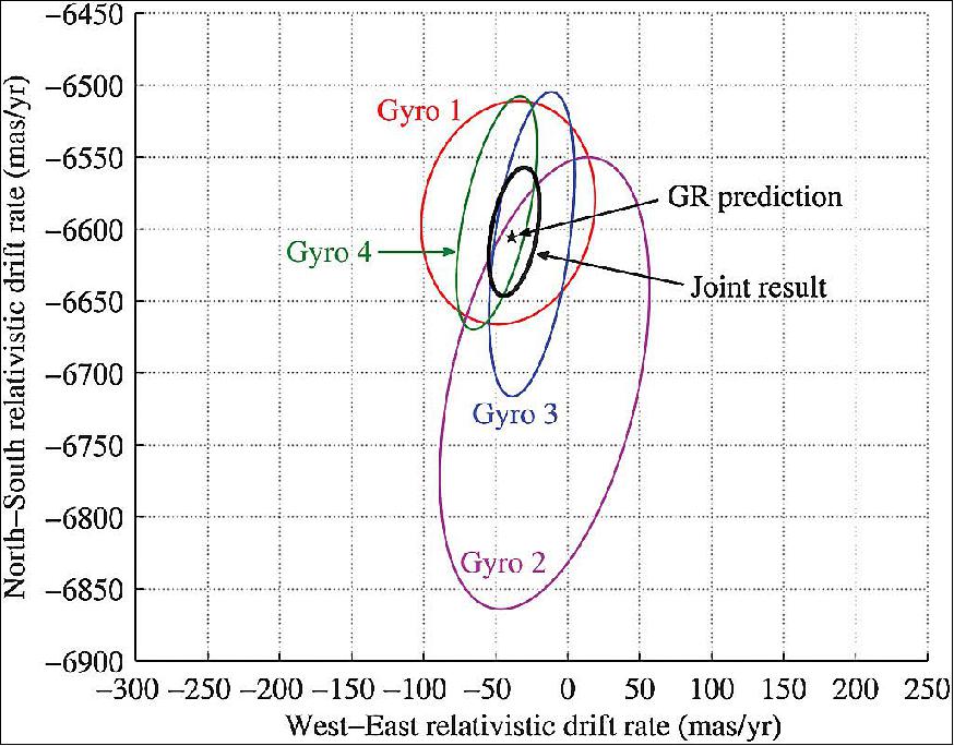
Results and conclusions: The four gyroscope signals were analyzed independently and the results combined and cross-checked in various ways. Table 3 lists the four relativity estimates and final joint result with 1σ errors, also plotted as 95% confidence ellipses in Figure 12. The values are referenced to inertial space by correcting for the solar geodetic contribution of 7:3 ± 0:3 mas/yr NS (North South) and -16:2 ± 0:6 mas/yr WE (West East), and for the guide star proper motion, 27:3 ± 0:1 mas/yr NS and -20:0 ± 0:1 mas/yr WE (the latter numbers are based on the declination and right ascension rates of 27:27 ± 0:11 mas/yr and -20:83 ± 0:10 mas/yr, respectively. 34) 35)
Note: 1 mas (milliarcsecond: 1 mas = 4:848 x 10-9 rad)
Source | rNS (Geodetic Measurement, mas/yr) | rWE (Frame-Dragging Measurement, mas/yr) |
Gyroscope 1 | -6588:6 ± 31.7 | -41.3 ± 24.6 |
Gyroscope 2 | -6707.0 ± 64.1 | -16.1 ± 29.7 |
Gyroscope 3 | -6610.5 ± 43.2 | -25.0 ± 12.1 |
Gyroscope 4 | -6588.7 ± 33.2 | -49.3 ± 11.4 |
Joint (weighted-average results for all four gyroscopes) | -6601.8 ± 18.3 | -37.2 ± 7.2 |
GR (General Relativity) prediction: Schiff-Einstein Predicted Theoretical Values | -6606.1 | -39.2 |
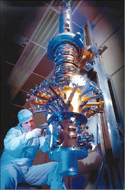
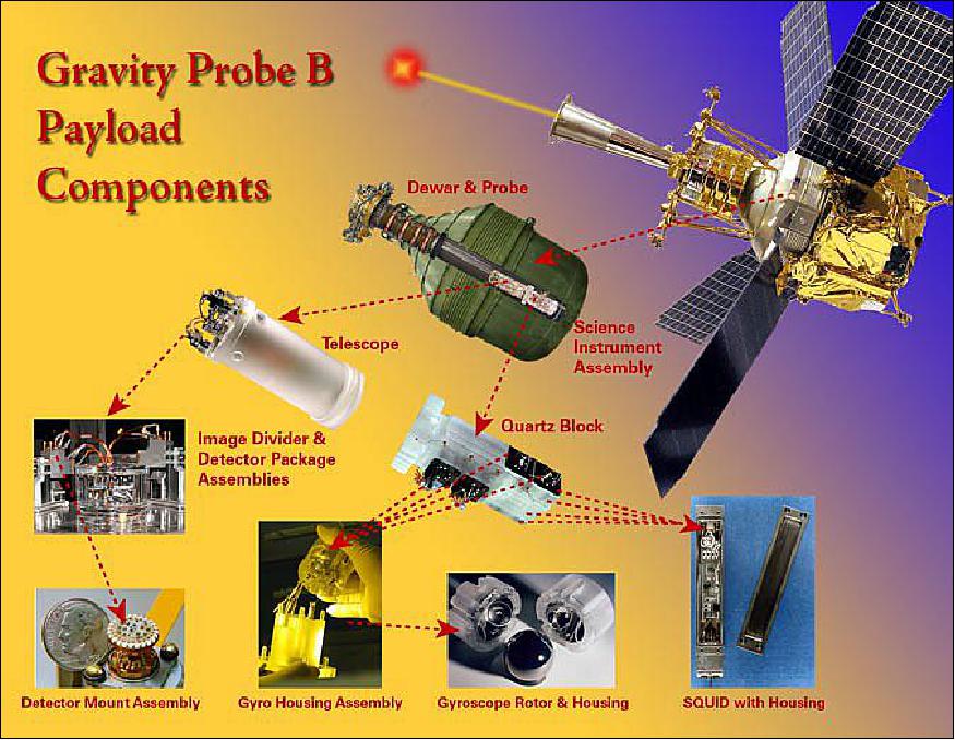
Experiment Payload (SIA)
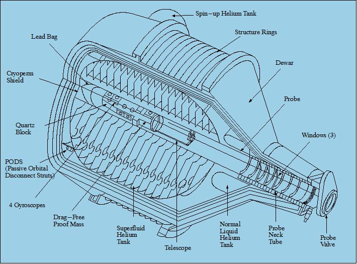
The GP-B payload is in effect a large `thermos bottle' in space. The science payload consists of a superfluid (2,440 l) helium dewar, within which a high-vacuum probe is installed, containing the SIA (Science Instrument Assembly), made up of a Quartz Block Assembly (QBA), which is optically contacted to a fused quartz Cassegrainian telescope. The QBA consists of four gyroscopes (for redundancy) and a drag-free proof mass sensor mounted in a precision-machined fused-quartz block. The spin axes of the four gyroscopes are aligned parallel to the line of sight to the guide star. The SIA is maintained at at a stable temperature of 1.8 K which provides the necessary stability of the precision alignment between the gyroscopes and the telescope. 36) 37)
A proof mass (in Gravity Probe B, a quartz sphere identical to a gyro rotor) floats within an evacuated cavity near the spacecraft's center of mass. The proof mass, being shielded from external accelerations, tends to follow an ideal gravitational orbit; and by sensing its position and applying thrust forces to make the spacecraft chase after it, the satellite can be made drag-free. The mean acceleration on the gyroscopes is reduced to 10-10 g; their performance improves by a factor of 1,000.
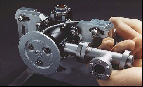
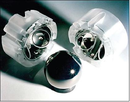
Each gyroscope (with the world's roundest sphere) is a 38 mm diameter sphere of homogeneous fused quartz with a uniform superconducting layer of niobium (Nb) coated on its surface. The coating thickness is 1.27 μm. The gyroscope is assembled inside a housing composed of two halves also made of fused quartz. Each housing half has three pairs of electrodes for electrostatic suspension of the gyroscope and raised support lands around each electrode to prevent electrical contact (when not suspended) between the gyroscope and the electrodes. In addition, the readout half has a thin-film Nb pickup loop located on its parting plane; the spin-up half has a spin-up channel with an inlet and an outlet for He gas spin-up of the gyroscope.
The four gyroscopes are aligned parallel to the telescope axis, two spinning clockwise and two counterclockwise, each gyroscope measuring both relativity effects. The difference in spin direction does not change the predicted effects; it does provide one of the many validation checks on the experiment. The gyroscopes are electrostatically suspended and then spun up to about 100 Hz by means of a helium gas at a temperature of 6.5 K. They are then evacuated to a pressure of ≤10-11 torr which, in conjunction with the averaging effect of rolling the S/C about the line-of-sight to the guide star, sufficiently minimizes torques due to differential gas damping. The proof mass sensor controls thrusters which compensate for the effects of residual drag on the S/C, and achieves an average acceleration at the gyroscopes of ≤ 10-11 g.
Two characteristics of the superconducting Nb play important roles in the performance of the gyroscope. First, the Nb coating makes an ideal equipotential surface for the electrostatic suspension; secondly, the London 38) magnetic dipole moment provides a means to readout the direction of the gyro spin axis. Note: The spinning superconducting rotor develops a magnetic `London moment' whose north-south axis exactly coincides with the rotor's spin axis. This direction is measured by a magnetometer of extreme sensitivity, known as the SQUID (Superconducting Quantum Interference Device), coupled to a superconducting loop onto the gyro housing. SQUIDs, which are very sensitive magnetometers, provide the gyroscope readouts. A SQUID has the capability to detect a field change of 5 x 10-14 Gauss within a few days, which corresponds to a gyro tilt of 0.1 milliarcseconds. 39)
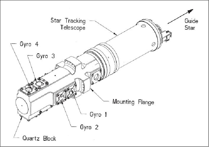
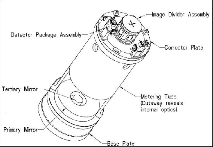
The gyroscope spin directions are related via a quartz block to the telescope viewing the guide star. Like the rest of the instrument, the telescope is made of fused quartz. Its aperture (i.e. primary mirror diameter) is 14.4 cm, overall length of 50.5 cm, folded optics design, modified Cassegrainian-type, focal length = 3.81 m (f/27). The guide star telescope rotates about its central axis, thereby providing a constant pointed reference direction to a star that is fixed on the celestial sphere. This setup provides the critical inertial reference frame for the spacecraft.
Within the dewar, surrounding the probe, is a shield formed of superconducting lead bags (foil) which almost completely excludes the Earth's magnetic field. Thus, the gyroscopes operate: a) at low temperature, b) at low pressure, c) in a low magnetic field, and d) in the low gravity of space.
The spin of the spacecraft is needed to average out potential error sources in GP-B (drifts in the telescope readout, Newtonian drift torques on the gyroscopes, etc.). Thus, the spin offers an important symmetry effect in the overall measurement concept.
The SIA is enclosed in a cylindrical cryogenic vacuum tube, 0.3 m in diameter and 2.4 m in length. The inside of the dewar vessel contains 2440 l of superfluid helium. The size of the dewar is 2.74 m in length and 2.64 m in diameter. The dewar, which maintains cryogenic temperatures on orbit for 18 months, serves as the main structural element of the S/C. The boil-off gas from the dewar, vented through proportional thrusters, provides thrust for attitude, translational and roll control of the S/C.
Magnetic shielding (DC and AC) is an essential feature of the experiment. For the London moment readout to work, the field trapped in the gyro rotor during cooling through its superconducting transition temperature must be below the value of 3 x 10⁻¹⁰ T (this is well below the limit achievable by conventional ferromagnetic shields). Equally important is to eliminate the AC disturbances from external magnetic fields such as the Earth's. The required AC shielding factor is 1012. These requirements are met by surrounding the instrument with a nested series of conventional and superconducting magnetic shields.
So as the spinning Earth drags space-time along with it, the satellite's four gyroscopes - themselves embedded in space-time - will twist a bit as well. By keeping a careful watch on the gyroscopes' orientation with respect to the (corrected) guide star, scientists can deduce whether this frame-dragging effect changes direction in which the gyroscopes point.
Some Challenging Technologies
The design and construction of the GP-B probe represented an enormous engineering challenge due to the measurement requirements of extremely minute changes in the orientation of gyroscopes housed within it. The dewar and the gyroscope each combine new physics and engineering principles, tailored for space. The thrusters for spacecraft pointing combine new mechanical and astronautical design principles. The porous plug and the instrument for measuring quartz homogeneity are engineering devices invented by physicists.
The "Kalman filter" for processing relativity data is a physics function developed by engineers. Even mathematical techniques cross. Methods from nuclear physic s theory have revolutionized the analysis of gyro performance. Methods from spacecraft orbital dynamics have simplified a correction to Schiff's formulae arising from the Earth's imperfect sphericity. - To bring the GP-B experiment to its present state of readiness has taken many years of research, advancing the frontiers in many areas: cryogenics , magnetics, quantum devices, telescope design, control systems, quartz fabrication techniques, metrology, and above all - gyroscope technology.
Simply stated, the technology requirements were so demanding that it took over 40 years from idea to launch. No spacecraft ever built has required such extreme demands on technology and testing.
Some background on the Gravity Probe A (GP-A) Mission
Gravity Probe A (GP-A) of NASA/MSFC and the Smithsonian Astrophysical Observatory (SAO), Cambridge, MA, was launched on June 18, 1976 on a Scout-D launch vehicle from Wallops Island, VA.The goal was to test Einstein's general theory of relativity. The probe attained an intended ballistic (sub-orbital) flight path with an apogee of 10,000 km (GP-A was only in space for one hour and 55 minutes in an elliptical flight trajectory over the Atlantic).
The principal payload was an atomic hydrogen-maser oscillator system with the objective to measure directly the effect of the gravitational potential on the frequency of a proper clock, a hydrogen maser. The objective of the experiment was to determine whether time progressed at a different rate in conditions where gravity is weaker. Hence, the sub-orbital clock tests included the Shapiro time delay experiment and the redshift experiments (the experiment verified Einstein's predicted gravitational redshift principle with a precision of 70 parts per million).
During this short trip, GP-A transmitted accurate measurements of slight changes in the clock's rate in lower gravity (the frequency of the maser was compared continuously during ascent and descent against a maser on the ground). The analysis of the GP-A experimental data verified a portion of Einstein's gravitation and relativity theories which are referred to as the "Principle of Equivalence (EP)" [Note: EP is a fundamental law of physics that states that gravitational and inertial forces are of a similar nature and often indistinguishable. EP in fact states that two fundamentally different quantities, inertia and passive gravitational mass, always be exactly proportional to one another]. GP-A was also the first test in space to explore the structure of space and time. It is known to many scientists as the "Red Shift Experiment" or the "Clock Experiment" (part of Einstein's special and general theories of relativity holds that changes in gravity and speed will alter the speed at which time flows). 40)
Launch
The probe was launched on June 18, 1976 from the NASA-Wallops Flight Center in Wallops Island, Virginia (suborbital mission). The probe was carried via a Scout rocket, and attained a height of 10,000 km, while remaining in space for 1 hour and 55 minutes, as intended. It returned to Earth by splashing down into the Atlantic Ocean. 41)
References
1) "Testing Einstein with Orbiting Gyroscopes, Gravity Probe B," Stanford University brochure
2) S. Buchman, C. W. F. Everitt, B. Parkinson, et al., "The Gravity Probe B Relativity Mission," Advances in Space Research, Vol. 25, No. 6, 2000, pp. 1177-1180
3) J. A. Lipa, D. H. Gwo, R. K. Kirschman, "Status of the cryogenic inertial reference system for the Gravity Probe B mission," SPIE, Vol. 1765 Cryogenic Optical Systems and Instruments V, 23-24 July 1992, San Diego, pp. 85-93
4) C. W. F. Everitt, D. Bardas, Y. M. Xiao, et al., "Three Papers on Gravity Probe B," presented at The Sixth Marcel Grossmann Meeting on Relativity, Kyoto, Japan, June 23-29, 1991
5) M. Tapley, et al., "Gradiometry Coexperiments to the Gravity Probe B and Step Missions," Advanced Space Research, Vol. 11, No. 6, 1991, pp. 179-182
6) C. W. F. Everitt, B. W. Parkinson, "The gravity probe B relativity mission," Fundamental Physics in Space II, Proceedings of the 32 nd COSPAR Scientific Assembly, July 12-19, 1998, Nagoya, Japan
7) Information provided by C. W. F. Everitt of Stanford University, Stanford, CA
8) "Gravity Probe B Testing Einstein's Universe," NASA Facts, http://www.nasa.gov/pdf/162789main_gpb_fs.pdf
9) John Mester, "The Gravity Probe B Relativity Mission," URL: http://luth2.obspm.fr/IHP06/lectures/mester-vinet/IHP-7GP-BMission.pdf
10) "Overview of the GP-B Mission," URL: http://einstein.stanford.edu/MISSION/mission1.html
11) "The Gravity Probe B in a Nutshell," URL: http://www.nasa.gov/pdf/168809main_gpb_nutshell-0506.pdf
12) Note: The first drag-free satellite to fly a completely gravitational orbit was Triad-1 of the US Navy, built by JHU/APL and launched Sept. 2, 1972. The development of the drag-free system on Triad-1 is a direct flight experiment of George Pugh's proposal.
13) D. B. DeBra, W. J. Bencze, C. W. F. Everitt, J. VandenBeukel, J. Kirschenbaum, "Proportional Helium Thrusters for Gravity Probe B," Proceedings of the AAS Guidance and Control Conference, Breckenridge, CO, USA, Feb. 1-6, 2008, paper: AAS 08-038
14) C. W. F. Everitt, S. Buchman, D. B. DeBra, G. M. Keiser, J. M. Lockhart, B. Muhlfelder, B. W. Parkinson, J. P. Turneaure, "Gravity Probe B: Countdown to Launch," NASA contract NAS8-39225 paper, 2000
15) G. M. Reynolds, R. H. Vassar, R. T. Parmley, D. Read, W. Reeve, K. Shaul, D. St. Clair, J. Vanden Beukel, "Payload and Spacecraft Technology for GP-B," Advances in Space Research, Vol. 25, No 6, 2000, pp. 1193-1197
16) E. B. Acworth, R. J. Bernier, N. J. Kasdin, D. B. DeBra, J. Lipa, C. W. F. Everitt, K. Triebes, L. Huff, "Design of an Artificial Star for Gravity Probe B: A Precision Light Beam for Testing a Cryogenic Space Telescope," AAS/AIAA Astrodynamics Conference, Sun Valley, Idaho, USA, Aug. 4-7, 1997, AAS 97-061
17) J. Li, W. J. Bencze, D. B. DeBra, G. Hanuschak, T. Holmes, G. M. Keiser, J. Mester, P. Shestople, H. Small, "On-orbit performance of Gravity Probe B drag-free translation control and orbit determination," Advances in Space Research, Vol. 40, Issue 1, 2007, pp. 1-10
18) http://einstein.stanford.edu/
19) Erica Hupp, George Deutsch, Steve Roy, "NASA's Gravity Probe B Mission Completes Data Collection," Oct. 3, 2005, URL: http://www.nasa.gov/home/hqnews/2005/oct/HQ_05293_probe_b.html
20) W. J. Bencze, D. B. DeBra, L. Herman, T. Holmes, M. Adams, G. M. Keiser, C. W. F. Everitt, "On-orbit performance of the Gravity Probe B drag-free translation system" Proceedings of the 29th Annual AAS GNC 2006 (Guidance & Navigation Conference), Breckenridge, CO, USA, Feb. 4-8, 2006, AAS 06-083
21) D. B. DeBra, W. J. Bencze, C. W. F. Everitt, J. VandenBeukel, J. Kirschenbaum, "Proportional Helium Thrusters for Gravity Probe B," Proceedings of the AAS Guidance and Control Conference, Breckenridge, CO, USA, Feb. 1-6, 2008, AAS 08-038
22) B. Kahn, "Scientists Provide First Public Peek At Gravity Probe B Results," Spacedaily, April 17, 2007, URL: http://www.spacedaily.com/reports/Scientists_Provide_First_Public_Peek_At_
Gravity_Probe_B_Results_999.html
23) W. J. Bencze, S. Buchman, B. Clarke, D. DeBra, C. W. F. Everitt, G. Green, M. I. Heifetz, D. N. Hipkins, G. M. Keiser, J. Li, J. A. Lipa, B. Muhlfelder, B. W. Parkinson, A. S. Silbergleit, M. Taber, J.P. Turneaure, S. Wang, "Gravity Probe B – Testing Einstein at the Limits of Engineering," Nuclear Physics B, Proceedings Supplements, Volume 166, April 2007, pp. 147-152
24) "The Gravity Probe B Experiment - Testing Einstein's Universe," Post Flight Analysis - Final Report, Preface & Executive Summary, October 2006, URL: http://www.nasa.gov/pdf/168808main_gp-b_pfar_cvr-pref-execsum.pdf
25) Mission update, Sept. 26, 2008, URL: http://einstein.stanford.edu/highlights/hl_092608.html
26) Mission Update, Nov. 12, 2009, URL: http://einstein.stanford.edu/highlights/status1.html
27) Barry Muhlfelder, "Gravity Probe B Overview," HEPL-AA Seminar, June 17, 2009, URL: http://einstein.stanford.edu/RESOURCES/presentations/T0133_GPB-Overview_Muhlfelder.pdf
28) Tony Phillips, "NASA Announces Results of Epic Space-Time Experiment," NASA, May 4, 2011, URL: http://science.nasa.gov/science-news/science-at-nasa/2011/04may_epic/
29) "NASA's Gravity Probe B Confirms Two Einstein Space-Time Theories," NASA, Press Release, May 4, 2011, URL: http://einstein.stanford.edu/content/press-media/results_news_2011/NASA_Press_Release.pdf
30) "Stanford's Gravity Probe B confirms two Einstein theories," Stanford University Press Release, May 4, 2011, URL: http://einstein.stanford.edu/content/press-media/results_news_2011/Stanford_Press_Release.pdf
31) "Public Announcement of GP-B Final Experimental Results," Mission update, April 26, 2011, URL: http://einstein.stanford.edu/highlights/status1.html
32) "Gravity Probe B Data Confirms Frame-Dragging and Geodetic Effect in Support of Einstein's General Theory of Relativity," Lockheed Martin Press Release, May 4, 2011, URL: http://einstein.stanford.edu/content/press-media/results_news_2011/Lockheed_Martin_Press_Release.pdf
33) "GP-B Status Upadate — May 4, 2011, URL: http://einstein.stanford.edu/highlights/status1.html#PRL_paper
34) C. W. F. Everitt, D. B. DeBra, B. W. Parkinson, J. P. Turneaure, J. W. Conklin, M. I. Heifetz, G. M. Keiser, A. S. Silbergleit, T. Holmes, J. Kolodziejczak, M. Al-Meshari, J. C. Mester, B. Muhlfelder, V. G. Solomonik, K. Stahl, P. W. Worden, Jr., W. Bencze, S. Buchman, B. Clarke, A. Al-Jadaan, H. Al-Jibreen, J. Li, J. A. Lipa, J. M. Lockhart, B. Al-Suwaidan, M. Taber, S. Wang, "Gravity Probe B: Final Results of a Space Experiment to Test General Relativity," Physical Review Letters, Vol. 106, 221101, June 3, 2011, URL: http://einstein.stanford.edu/content/sci_papers/papers/PhysRevLett.106.221101.pdf
35) Clifford M. Will, "Finally, results from Gravity Probe B," Physics, Vol. 4, 43, 2011, URL: http://einstein.stanford.edu/content/press-media/results_news_2011/C_Will-Physics.4.43-Viewpoint.pdf
36) S. Buchman, C. W. F. Everitt, B. Parkinson, et al., Gyroscopes and Charge Control for the Relativity Mission Gravity Probe B," Advances in Space research, Vol. 25, No 6, 2000, pp. 1181-1184
37) S. Buchman, B. Muhlfelder, J. Turneaure, "Gravity Probe B Science Instrument Assembly (SIA)," APS (American Physical Society), Jacksonville, FLA, April 14-17, 2007
38) When a superconductor like niobium spins, it generates a magnetic field effect known as the `London moment,' after physicist Fritz London (1900-1954). In 1948 Fritz London predicted that a spinning superconductor would develop a magnetic moment, exactly aligned with its instantaneous spin axis.
39) "Low-temperature system provides thermal insulation between detector electronics operating at 80 K and a quartz telescope operating at 2.5 K," URL: http://einstein.stanford.edu/content/spinoffs/detector.html
40) R. F. C. Vessot, M. W. Levine, "A Test of the Equivalence Principle Using a Space-Borne Clock," General Relativity and Gravitation, Vol. 10, No. 3, 1979, pp. 181-204
41) "Gravity Probe A," NASA/JPL, URL: http://funphysics.jpl.nasa.gov/technical/grp/grav-probea.html
42) "Gravity Probe A," ESA, Nov. 9, 2015, URL: http://www.esa.int/spaceinimages/Images/2015/11/Gravity_Probe_A
The information compiled and edited in this article was provided by Herbert J. Kramer from his documentation of: "Observation of the Earth and Its Environment: Survey of Missions and Sensors" (Springer Verlag) as well as many other sources after the publication of the 4th edition in 2002. - Comments and corrections to this article are always welcome for further updates (eoportal@symbios.space)
Overview Spacecraft Launch Mission Status Payload References Back to Top