GEOS (GEOstationary Scientific Satellite), ESA
EO
ESA
Mission complete
Launched in April 1977 and July 1978 respectively, GEOS-1 (Geostationary Earth Orbit Satellite-1) and GEOS-2 were two satellites operated by the ESA (European Space Agency). They monitored Earth’s magnetic field until 1978 and 1983 respectively.
Quick facts
Overview
| Mission type | EO |
| Agency | ESA |
| Mission status | Mission complete |
| Launch date | 20 Apr 1977 |
| End of life date | 23 Jun 1978 |
| CEOS EO Handbook | See GEOS (GEOstationary Scientific Satellite), ESA summary |
Summary
Mission Capabilities
Both GEOS-1 and GEOS-2 performed the same seven experiments which required the same instruments onboard. A search coil magnetometer and a fluxgate magnetometer studied magnetic fields; the deflection of electrons from an electron gun was used to study the magnetic and electric fields; two electrostatic analysers and an ion composition sensor studied plasma’s interaction with the magnetic field; and ten electrostatic analysers and an electron spectrometer measured the pitch-angle distribution of electrons.
Performance Specifications
The search coil magnetometer measured AC (alternating current) magnetic field variations of up to 30 kHz whilst the fluxgate magnetometer measured DC (direct current) and ULF (ultra low frequency) magnetic field variations. The two electrostatic analysers monitored plasma up to an energy of 500 eV whilst the ion composition sensor monitored plasma up to an energy of 16 keV. The 10 electrostatic analysers monitored electrons with an energy of 0.2 - 20 keV whilst the electron spectrometer monitored electrons with an energy of 20 - 300 keV.
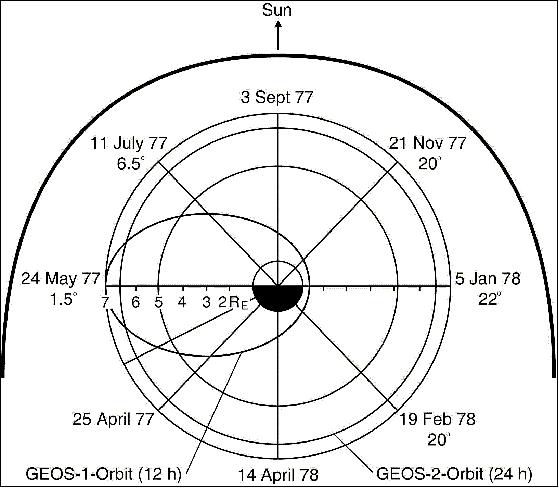
GEOS-1 undertook an elliptical orbit (2682 - 38475 km) with an inclination of 26.6°, and a period of 12 hours. GEOS-2 undertook a geostationary orbit with an altitude of 35,786 km.
Space and Hardware Components
It was originally planned to just have a single satellite (GEOS-1) in geostationary orbit for the GEOS mission but due to a separation problem between stages two and three, GEOS-1 was left in an elliptical orbit. As such, GEOS-2 was launched.
Weighing 573 kg each, both GEOS-1 and GEOS-2 were launched aboard a Thor-Delta launch vehicle from the Cape Canaveral Space Force Station.
GEOS (GEOstationary Scientific Satellite), ESA - GEOS Program
GEOS-1 GEOS-1 Launch GEOS-1 Mission Status Sensor Complement GEOS-2 GEOS-2 Launch GEOS-2 Mission Status References
The GEOS research missions (GEOS-1 and -2) of ESA had the objective to study the particles, fields and plasmas of the Earth's magnetosphere from a geostationary orbit. The definition of the GEOS program was actually started in the late 1960s under ESRO (European Space Research Organization) management, the predecessor organization of ESA (ESA was founded in 1975).
GEOS was conceived by ESRO as a broad scientific mission to be accomplished by a set of experiments chosen among proposals coming from the scientific community and integrated into the payload. The GEOS experimenters from the very beginning discussed ways to achieve the maximum scientific value from the satellite and defined common modes of payload operation and data handling (a GEOS coordination committee was established in 1972). Because of its unique orbit and the sophistication of its payload, GEOS was selected as the reference spacecraft in the world-wide IMS (International Magnetospheric Study) program during the period 1977-1982.
GEOS-1
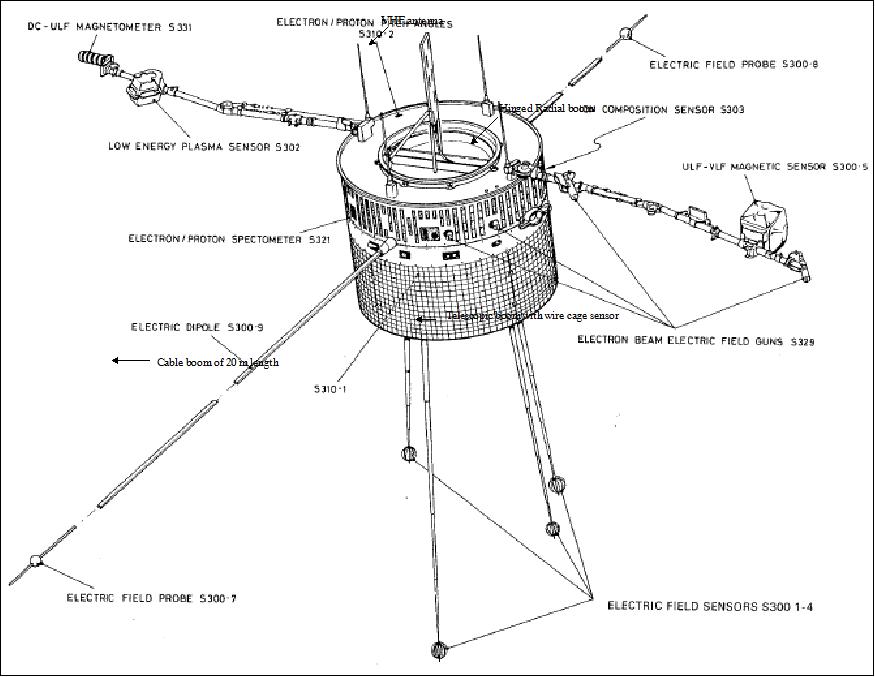
The S/C structure consisted of a cylindrical bus, 132 cm high and 164.5 cm in diameter, equipped with several booms. The S/C was spin-stabilized (nominal spin rate of 10 rpm). Attitude was measured by sun and Earth sensors and an accelerometer. Surface mounted solar cells provided energy of > 110 W (BOL). A total of 7200 cells were mounted on the cylindrical bus.
Spacecraft launch mass of 574 kg, design life of 2 years. The spacecraft integration was performed at British Aircraft Corporation (Bristol) as prime contractor, spacecraft testing was done at ESA/ESTEC. 1) 2) 3) 4) 5)
An apogee kick motor of 269 kg and 30.6 kg of propellant, was used for injection from GTO into GEO. Six 15 N thrusters provided reaction control.
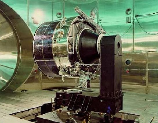
Legend to Figure 1: GEOS-1 is being prepared for boom deployment tests in the dynamic spin test chamber at ESA/ESTEC.
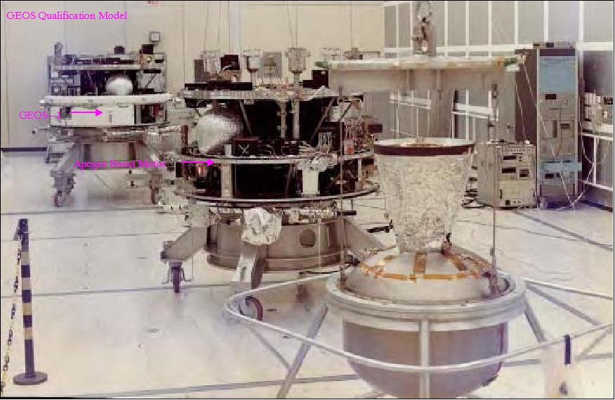
Legend to Figure 2: In front of GEOS-1 spacecraft (middle) is the Apogee Boost Motor. In the background is the GEOS Qualification Model, later modified as GEOS-2.
Launch
The GEOS-1 spacecraft was launched on April 20, 1977 by Thor Delta vehicle from Cape Canaveral, FLA, USA (COSPAR designation: 77-029A).
Unfortunately, a booster/separation problem meant that geostationary orbit could not be achieved. Hence, the S/C was placed into a 12 hour final orbit where the instruments could make the planned measurements for about 6 hours of each revolution between 5 and 7 Earth radii. In this orbit the mission was still able to serve as a core or reference spacecraft for the IMS, and carried out planned correlative measurements with extensive ground-based networks in Scandinavia and conjugate point measurements between a station in Iceland and in Antarctica.
Orbit: GEOS-1 was left in a GTO orbit due to a stage 2/3 separation problem; apogee of 38,475 km, perigee of 2936 km, inclination of 26.6º, period of ~ 12 hours.
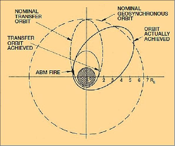
Legend to Figure 4: The originally planned and launch-failure-degraded GEOS-1 orbits. The spacecraft's apogee boost motor was fired at the point indicated to achieve a 12 hour eccentric orbit as the best recovery compromise.
Application: Detailed study of the magnetosphere's radial distribution of plasma, particles and waves (in conjunction with ground-based observations in Scandinavia, Iceland, Antarctica, and Alaska). Magnetospheric transport phenomena.
RF communications: Transmission rate of 100 kbit/s (continuously at a frequency of 2299.5 MHz, no onboard data storage) containing high-speed data (wide-band analog and correlator data from the wave experiment), and low-speed data, consisting of low-frequency data from the wave experiment and the data from all other experiments. Uplink at 149.48 MHz (VHF).
Mission Status
• In April 2017, ESA is remembering the 40th anniversary of the GEOS-1 launch on April 20, 1977. 7)
- GEOS-1 was designed for geostationary orbit to study the particles, fields and plasmas of Earth's magnetosphere using seven instruments provided by ten European laboratories. Because of its high orbit and the sophistication of its payload, GEOS-1 was selected as the reference mission for the global IMS (International Magnetospheric Study).
- As a consequence of the lower than geostationary orbit, the mission's qualification model was subsequently launched as GEOS-2 on 14 July 1978 with an identical payload and successfully reached the planned orbit. In spite of its orbit, GEOS-1 made a significant contribution to IMS, and its mission formally ended on 23 June 1978.
• The S/C performed measurements in its elliptical orbit for 14 months (return of very useful data).
Sensor Complement
The scientific payload was made up of 7 different instruments provided by 10 European laboratories. Use of simultaneous waves and particle experiments along with electric and magnetic fields and total plasma density. 8) 9)
S 300 (Search Coil Magnetometer)
S-300 was developed by CRPE, France, ESA/ESTEC, and the Danish Space Research Institute (DSRI). Objectives: study of magnetospheric wave phenomena in both electric and magnetic domains; measurement of AC magnetic fields up to 30 kHz; DC/AC electric fields and plasma resonances up to 80 kHz; mutual and self-impedance. The instrument consisted of: 10) 11)
• 2 vitreous carbon spheres mounted on radial booms (42 m tip-to-tip)
• 2 sets of three-axis search coil magnetometers, one for the ULF/ELF range and one for the VLF range (each is mounted on the locking 3 m booms at a distance of 2 m from the spacecraft), 4 meshed spheres mounted at the end of the 2.5 m axial booms.
S 302 (Electrostatic Space Plasma Analyzer)
S 302 consisted of 2 units, designed/developed by the Mullard Space Science Laboratory (MSSL), London, UK. Objectives: measurement of thermal plasma (electron, protons) up to 500 eV in the magnetosphere. The hemispherical electrostatic analyzers are boom-mounted with a novel sensor bias control in order to overcome difficulties associated with electron emission from spacecraft surfaces and the consequent charging.
S 303 (Combined Electrostatic and Magnetic Analyzer)
S 303 was designed/developed by the University of Bern and MPI, Garching. Objectives: measurement of the composition (1-140 amu) and energy spectra of ions up to 16 keV.
S 310 (Ten Electrostatic Analyzers)
S 310 was designed/developed by the Kiruna Geophysical Observatory, Sweden. Objectives: measurement of the pitch-angle distribution of electrons and protons in the 0.2-20 keV energy range.
S 321 (Magnetic Deflection System followed by Solid-state Detectors)
S 321 was designed by MPAe, Katlenburg-Lindau, Germany. Objectives: measurement of the pitch-angle distribution for electrons (20-300 keV) and protons (20 keV - 3 MeV).
S 329 (Tracing of Electron Beam over one or more gyrations)
S 329 was designed by MPI Garching. Objectives: measurement of DC electric field grad |B|.
S 331 (Fluxgate Magnetometer)
S 331 was designed/developed by CNR, Frascati, Italy, and by NASA/GSFC. Objectives: measurement of the three components of the DC and ULF magnetic field. The instrument was boom-mounted.
GEOS-2
The GEOS-2 satellite of ESA carried the same payload (sensor complement) as GEOS-1 and is regarded a replacement for GEOS-1 (GEOS-2 was originally considered as a spare or backup spacecraft). Objective: Measurement of fluctuations in the magnetic field which are picked up by small antennas (about 25 cm). GEOS-2 had six antennas to measure the three components of the field in two frequency bands. 12)
The spacecraft was cylindrical with a height of 1.321 m. The total mass, excluding propellants, was 273.6 kg (launch mass of 573 kg). GEOS-2 featured four telescopic axial booms 2.5 m in length for the wire mesh spheres of an AC electric field experiment, two 20 m cable booms for magnetic and electric field sensors and for an excitation antenna for plasma resonances, and two locking radial booms 3 m in length for a variety of instruments.
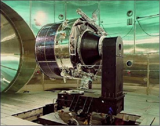
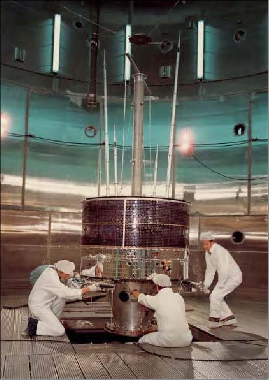
Legend to Figure 5: The GEOS qualification model is mounted onto the moment-of-inertia measurement machine in the Dynamic Test Chamber at ESTEC.
Launch
GEOS-2 was launched July 14, 1978 on a Thor-Delta vehicle from Cape Canaveral, FLA. 13)
Orbit: initial perigee of 36,009 km, initial apogee of 36,071 km, inclination at 11.8º, positioned at 37º East (initially).
Mission Status
• On January 25, 1984, GEOS-2 became the first ESA spacecraft to be removed from geostationary orbit. The spacecraft was raised to a final orbital altitude of 42,426 km. This resulted into an Earth drifting orbit (in the westward direction at a rate of 3.3º/day) from its original longitude at 36º east. At this rate, GEOS-2 completed one revolution relative to the rotating Earth in 108 days. 14)
• GEOS-2 provided two years of data, was placed in hibernation for eight months, then revived for eight months in 1981 to support the EISCAT program of upper atmosphere motion measurements. GEOS-2 remained in use until the end of 1983. Periodic monitoring support (1984) of the chemical releases of the AMPTE mission. 15)
• The GEOS-1/-2 were the first spacecraft anywhere to carry a totally conductive coating - even over their solar panels. An electron beam experiment and a pair of probes, 40 m apart, provided independent measurements of the electric field surrounding the S/C. The S/C surface-treatment technology was confirmed.
References
1) D. E. Mullinger, "The Special Technical Features of GEOS," ESA Bulletin No 9, May 1977, pp. 4-11
2) G. Schmidt, M. Newns, B. Henson, "The Booms and Mechanisms of GEOS," ESA Bulletin No 9, May 1977, pp. 22-27
3) C. Kalweit, A. Pitt, "Electromagnetic Cleanliness - An Important Characteristic of the GEOS Satellite," ESA Bulletin No 9, May 1977, pp. 28-34
4) "More than Thirty Years of Pioneering Space Activities," ESA publication BR-142, 1999, compiled by Andrew Wilson, pp. 46-49
5) "GEOS," ESA brochure BR-250, June 2005, pp.66-69, URL: http://www.esa.int/esapub/br/br250/br250.pdf
6) "GEOS-1," ESA Bulletin No 117, Feb. 2004, p. 57, URL: http://www.esa.int/esapub/bulletin/bullet117/chapter7_bul117.pdf
7) "The way they were — GEOS-1 being tested at ESTEC," ESA, April 26, 2017, URL: http://www.esa.int/spaceinimages/Images/2017/04/GEOS-1_being_tested_at_ESTEC
8) GEOS - Projects under Development, ESA Report to COSPAR, Jan. 1977, pp. 112-123
9) K. Knott, "GEOS at the Center of a World-wide Study of the Earth' Magnetosphere," ESA Bulletin No 9, May 1977, pp. 12-16
10) D. Jones, "Introduction to the S-300 wave experiment onboard GEOS," Space Science Reviews, Vol. 22, 1978, pp. 327-332
11) "Measurements of electric and magnetic wave fields and of cold plasma parameters on-board GEOS-1. Preliminary results," Planetary and Space Science, Vol. 27, 1979, pp. 317-339
12) "GEOS," Interavia Space Directory 1992-93, pp. 155-156
13) http://rammb.cira.colostate.edu/dev/hillger/esa-geos.htm
14) P. Beech, M. Soop, J. van der Ha, "The de-orbiting of GEOS-2," ESA Bulletin, No 38, May 1984, pp. 86-89
15) S. Perraut, A. Roux, P. Robert, R. Gendrin, J. A. Sauvaud, J. M. Bosqued, G. Kremser, A. Korth, "A systematic study of ULF waves above FH+ from GEOS-1 and 2 measurements and their relationships with proton ring current distributions," Journal of Geophysical Research, Vol. 87, 1982, pp. 6219-6236
16) "Past, Present and Future Missions," ESS 265, UCLA, URL:
http://www-ssc.igpp.ucla.edu/personnel/russell/ESS265/Ch3.html
The information compiled and edited in this article was provided by Herbert J. Kramer from his documentation of: "Observation of the Earth and Its Environment: Survey of Missions and Sensors" (Springer Verlag) as well as many other sources after the publication of the 4th edition in 2002. - Comments and corrections to this article are always welcome for further updates (eoportal@symbios.space).
GEOS-1 GEOS-1 Launch GEOS-1 Mission Status Sensor Complement GEOS-2 GEOS-2 Launch GEOS-2 Mission Status References Back to top