GEO-KOMPSAT-2
EO
Ocean colour instruments
Atmosphere
Ocean
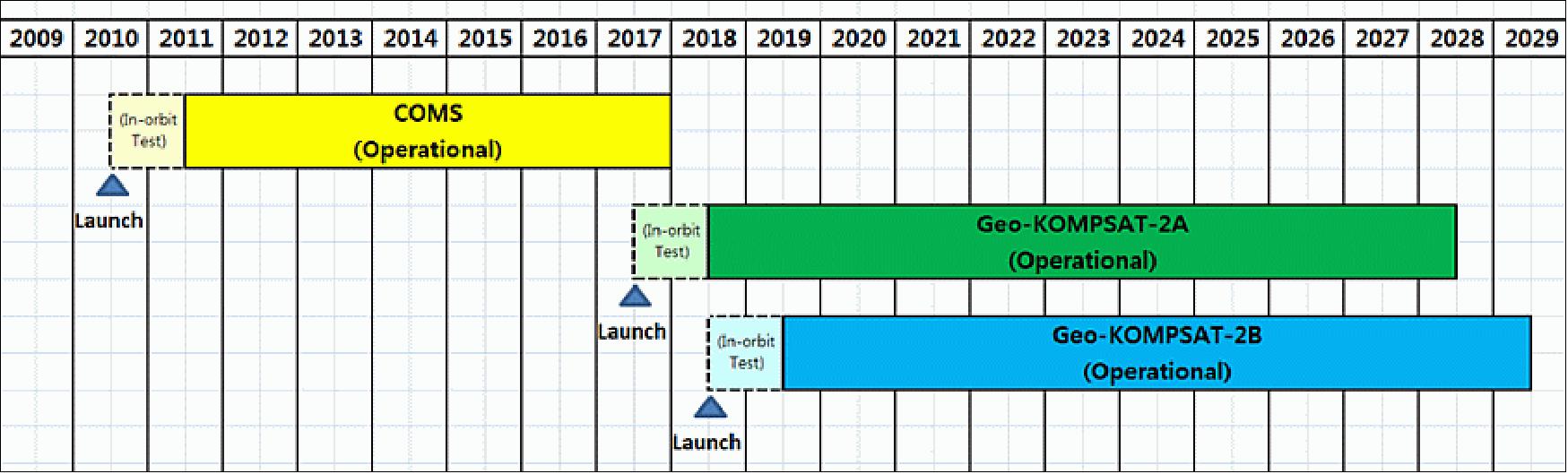
GEO-KOMPSAT-2 (Geostationary - Korea Multi-Purpose Satellite-2) is a twin constellation mission from the Korean Meteorological Administration (KMA) inclusive of GEO-KOMPSAT-2A (GK-2A) and GEO-KOMPSAT-2B (GK-2B) and is a continuation of the Korean Communications, Ocean and Meteorological Satellite program (COMS). The objective of the mission is to obtain geostationary meteorological data for monitoring of meteorological phenomena in the Asia-Oceania region. GK-2A launched in December 2018 and GK-2B launched in February 2020.
Quick facts
Overview
| Mission type | EO |
| Agency | KARI, BATC, KIOST, NIER, KMA, L3Harris |
| Mission status | Operational (nominal) |
| Launch date | 04 Dec 2018 |
| Measurement domain | Atmosphere, Ocean, Land, Snow & Ice |
| Measurement category | Cloud type, amount and cloud top temperature, Liquid water and precipitation rate, Atmospheric Temperature Fields, Cloud particle properties and profile, Ocean colour/biology, Aerosols, Radiation budget, Multi-purpose imagery (land), Surface temperature (land), Albedo and reflectance, Surface temperature (ocean), Atmospheric Humidity Fields, Ozone, Trace gases (excluding ozone), Ocean topography/currents, Sea ice cover, edge and thickness, Snow cover, edge and depth, Atmospheric Winds |
| Measurement detailed | Cloud top height, Aerosol absorption optical depth (column/profile), Ocean chlorophyll concentration, Downward long-wave irradiance at Earth surface, Cloud optical depth, Precipitation intensity at the surface (liquid or solid), Aerosol optical depth (column/profile), Cloud type, Cloud imagery, Cloud liquid water (column/profile), Land surface imagery, Upward short-wave irradiance at TOA, Upward long-wave irradiance at TOA, Cloud drop effective radius, Aerosol effective radius (column/profile), Cloud ice effective radius (column/profile), Fire fractional cover, Earth surface albedo, Atmospheric specific humidity (column/profile), O3 Mole Fraction, Atmospheric temperature (column/profile), Land surface temperature, Sea surface temperature, NO2 Mole Fraction, Sea-ice cover, Snow cover, Cloud top temperature, Wind profile (horizontal), Atmospheric stability index, Volcanic ash, SO2 Mole Fraction, Downward short-wave irradiance at Earth surface, Upwelling (Outgoing) long-wave radiation at Earth surface, Visibility, Cloud mask, Aerosol Layer Height, Water vapour imagery, Turbulence, Ocean velocity, Cloud top pressure |
| Instruments | GEMS, Advanced GOCI, AMI |
| Instrument type | Ocean colour instruments, Imaging multi-spectral radiometers (vis/IR), Atmospheric chemistry |
| CEOS EO Handbook | See GEO-KOMPSAT-2 summary |
Summary
Mission Capabilities
GEO-KOMPSAT-2A carries two instruments: the Advanced Meteorological Imager (AMI) and the Korean Space Environment Monitor (KSEM). AMI is a multi-spectral radiometer that provides continuous monitoring capability for the near real-time generation of high-resolution meteorological products and long-term change analysis of sea surface temperature and cloud coverage. KSEM consists of a Particle Detector (PD), Magnetometer (MAG), and a Satellite Charging Monitor (SCM) that are used to monitor the space environment and collect data on radioactive environmental hazards to the spacecraft.
GEO-KOMPSAT-2B also carries two instruments: the Geostationary Environment Monitoring Spectrometer (GEMS) and the Advanced Geostationary Ocean Colour Imager-II (GOCI-II). GEMS is a medium-resolution spectrometer that conducts measurements of atmospheric chemistry and the precursors of aerosols and ozone in high temporal and spatial resolution over Asia. GOCI-II is a multi-purpose imager that measures ocean colour, as well as monitors coastal and land resources.
Performance Specifications
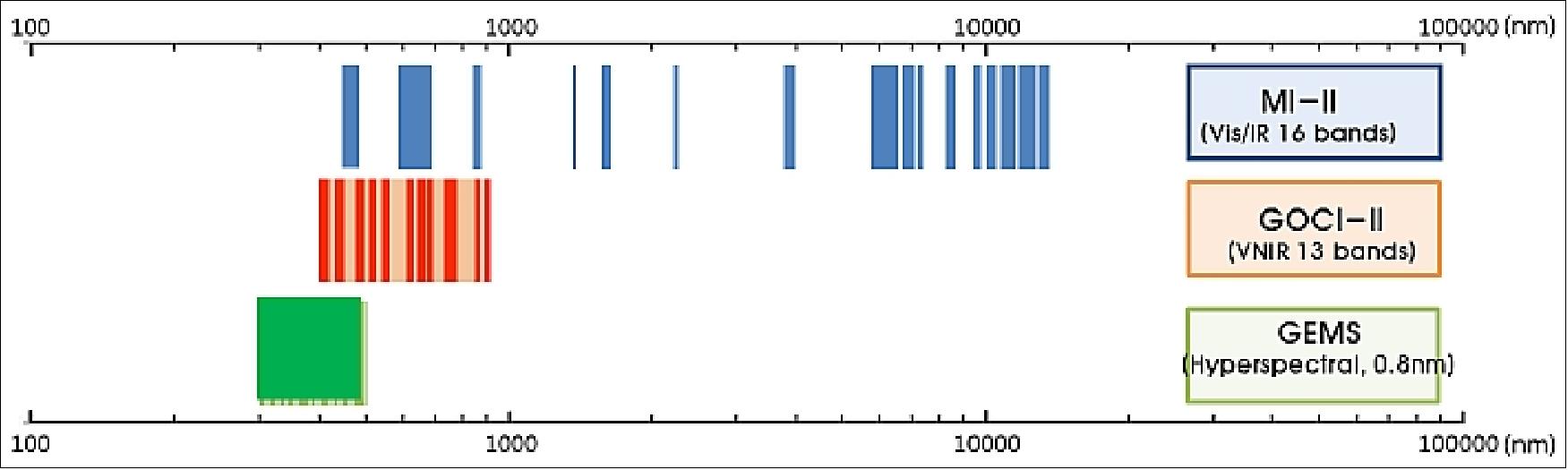
AMI images in 16 spectral channels, ranging from visible to thermal infrared (wavelengths between 0.47 - 13.3 μm). The spatial resolution ranges from 0.5 - 1.0 km for the visible channels, and 2 km for the infrared bands. The observation time in full disk mode is 15 minutes, while in local area mode, the observation time is 30 seconds. AMI has a field of view of 0.9° x 1.9°, a field of regard of 22°, and an aperture of 270mm.
GEMS is a hyperspectral imager, with a spectral range of 300 - 500 nm and spectral resolution of less than 0.6nm, sampling at less than 0.2 nm intervals. Using a scanning UV-Visible spectrometer, its observations provide a set of tropospheric column products over the Asia-Pacific region at spatial resolution of about 8 km and temporal resolution of 1 hour.
GOCI-II images in 12 visible and near-infrared bands, with one additional wideband, covering a spectral range of 380-900 nm. The instrument can image an area of 2500 km2 of the North-East Asian Sea in local area mode, with a spatial resolution of 300 m.
Space & Hardware Components
GEO-KOMPSAT-2 has ground systems designed to support missions and operations, composed of the SOC (Satellite Operations Center), NMSC (National Meteorological Satellite Center), KOSC (Korea Ocean Satellite Center), and ESC (Environmental Satellite Center). The satellites use S-band, X-band, and L-band communication frequencies, with X-band used for the downlink of payload data and the downlink of UHRIT (Ultra High Rate Information Transmission) dissemination channel.
The Korea Aerospace Research Institute (KARI) developed the GEO-KOMPSAT-2 platform, basing the system design and flight software development on COMS. Northrop Grumman provided the Scalable SIRU (Space Inertial Reference Units) devices, an inertial reference system for each of the two GEO-KOMPSAT-2 satellites, while Airbus Defence and Space delivered the complete propulsion subsystem and the structure of the medium-sized/small geostationary satellite platforms.
GEO-KOMPSAT-2 (Geostationary - Korea Multi-Purpose Satellite-2) Program / Cheollian-2 / GK-2
Spacecraft Launch Mission Status Sensor Complement Ground Segment References
KMA (Korea Meteorological Administration) is planning for the follow-on geostationary meteorological satellite (GEO-KOMPSAT-2) to continue the Korean COMS (Communications, Ocean, Meteorological Satellite) mission. From 2009 onwards, KMA has prepared a feasibility study for the GEO-KOMPSAT-2 program under the cooperation of the following Ministries: Ministry of Science, ICT and Future Planning (MSIP), Ministry of Oceans and Fisheries (MOF), and Ministry of Environment (ME) of the Korean government. The GEO-KOMPSAT-2 program has been approved in September 2010, and was kicked off in the middle of 2012. 1)
Note: The nickname Cheollian means long distance view (literally “Thousand Li View”) in Korean.
KMA/NMSC (Korea Meteorological Administration/National Meteorological Satellite Center) of Korea started the COMS-Next (GEO-KOMPSAT-2) program with the overall objective to obtain geostationary meteorological data for continuous monitoring of meteorological phenomena in the Asia-Oceania region.
Specific mission goals are: 2)
• Continuing the COMS (Communication, Ocean and Meteorological Satellite) meteorological mission
• Improving the severe weather monitoring
- Higher frequency of observation
- Retrieving the atmospheric structure (pseudo-sounding)
• Improving the support of the NWP (Numerical Weather Prediction) model with an efficient data assimilation model
• Intensifying the environment & climate monitoring
- Various surface information retrieval
- Air pollution monitoring
- Establishing long-term observation data.
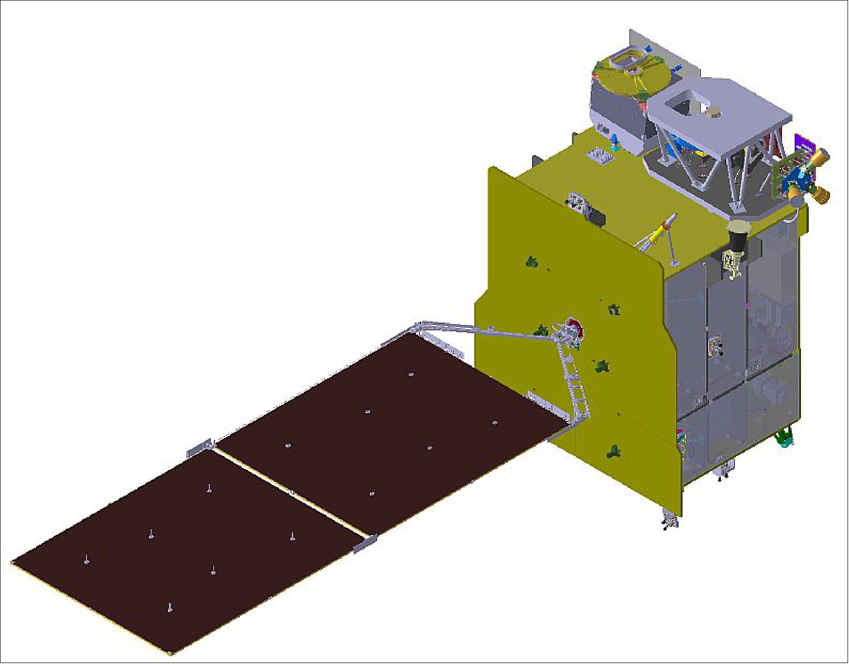
The GEO-KOMPSAT-2 program comprises two satellites for multi-purpose applications: GEO-KOMPSAT-2A for meteorological missions and GEO-KOMPSAT-2B for ocean and environmental monitoring. KARI (Korea Aerospace Research Institute) of Daejeon, Korea, is responsible for the development of the GEO-KOMPSAT-2 space segment while KMA/NMSC implements the ground segment. 3)
Spacecraft
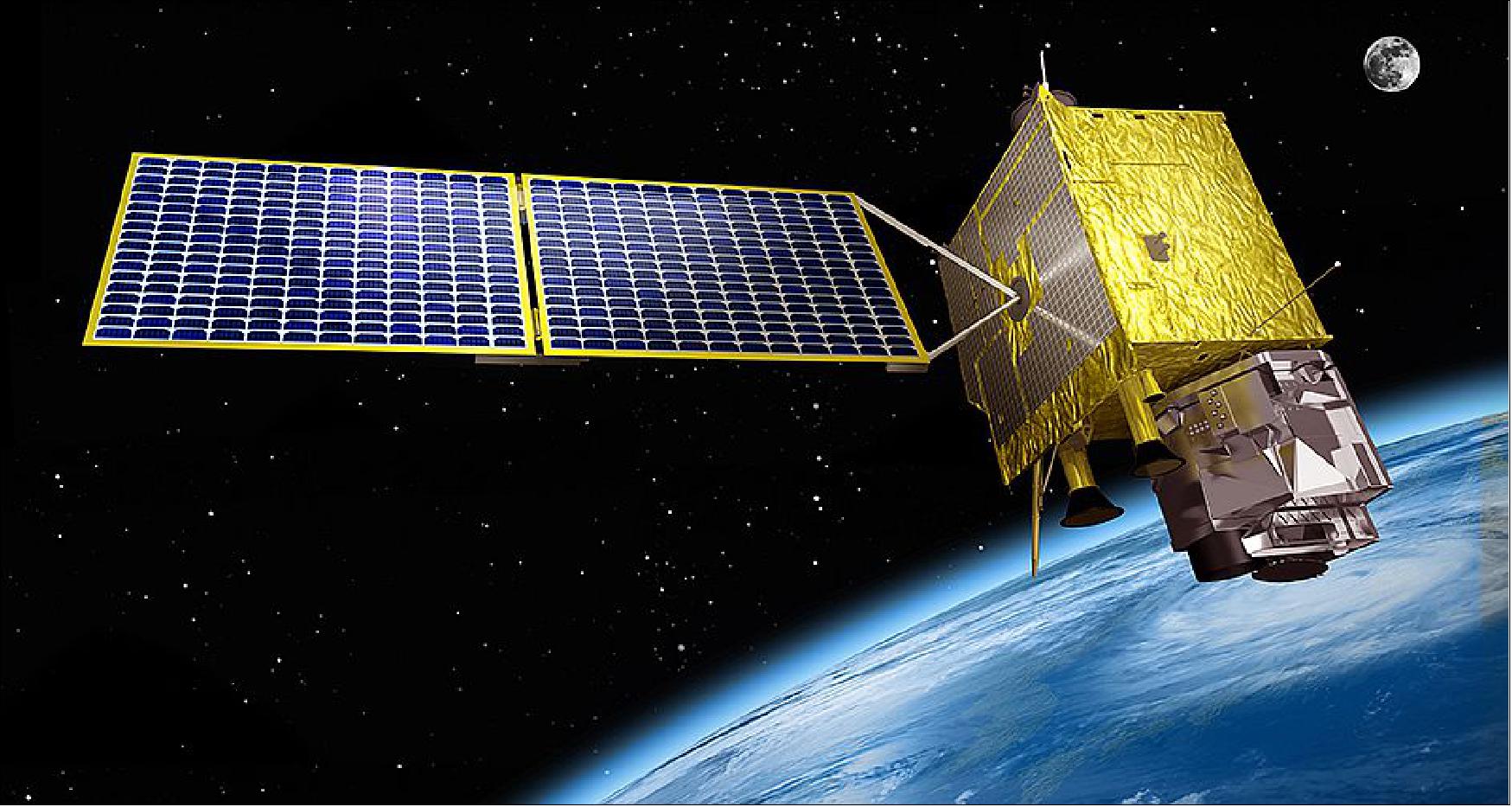
The GEO-KOMPSAT-2 (GK-2) satellites will inherit the mission of COMS(Cheollian-1) to observe the weather and ocean environment and strengthen the national capability to monitor the environment around the Korean Peninsula. Two satellites will be developed: a weather and space weather observation satellite (GK-2tA) and ocean and environmental observation satellite (GK-2B). 5) 6)
Meteorological Mission: GK-2A (GK2A)
• The objective is to continue and enhance the COMS meteorological observation mission.
• To monitor weather and climate phenomena with an enhanced measurement cycle.
• To monitor more accurately high-impact weather events with high spatial resolution.
The weather observation capability of GK-2A will be more than four times greater than that of COMS, while the observation interval and observation channels will both be improved more than threefold. The satellite is expected to greatly improve the accuracy of precision weather observation and weather forecasting, as well as enhance the capability to monitor and forecast unusual weather conditions in the Korean Peninsula and the Asian region.
The prime contractor for the design and development of the GK-2 satellites is KARI (Korea Aerospace Research Institute). The platform is being developed using procured qualified components, produced in Korea
Ensuring the GK2 system development under KARI’s responsibility (Ref. 6)
• GK2 platform is being developed by KARI
- The system design and flight software development are performed based upon COMS and previous knowledge and experience of KARI having in mind the maximum commonality between GK2A and GK2B
- Some units are manufactured and qualified by Korean industries with KARI’s involvement
- Already qualified hardware are procured from qualified manufacturers
- Observation data communication subsystem (ODCS) for payloads is developed as a part of the platform
- As a conservative approach, Software Test Bed (STB), Electric Test Bed (ETB) are developed prior to Flight Model
- Also, Structure and Thermal Model (STM) are developed and qualified prior to Flight Model.
In June 2014, KARI awarded a contract to Northrop Grumman to provide the Scalable SIRU (Space Inertial Reference Units) devices, an inertial reference system for each of the two GEO-KOMPSAT-2 satellites. The Scalable SIRU is the industry standard for high-precision, long-life attitude control solutions supporting commercial, government and civil space missions. At the heart of the Scalable SIRU is Northrop Grumman's patented HRG (Hemispherical Resonator Gyro) technology. HRGs have been used in space without a mission failure for more than 26 million operating hours and have been launched aboard more than 100 spacecraft. Since 2007, Northrop Grumman has supplied the Scalable SIRU for satellites developed and operated by KARI, including KOMPSAT-3, KOMPSAT-3A and KOMPSAT-5. 7)
In September 2014, KARI awarded Airbus Defence and Space a €45 million contract to deliver important subsystems and equipment for the two GEO- KOMPSAT-2 platforms (GK-2A and GK-2B). 8) Airbus Defence and Space will deliver the complete propulsion subsystem and the structure of the medium-sized/small geostationary satellite platforms, which have a launch mass of three to four tons. The Electronics Business Line of Airbus Defence and Space will supply the GK2 satellites with power and avionics units, while the Space Systems Business Line will provide them with a fully integrated propulsion subsystem consisting of the central cylinder structure, the chemical propulsion and the associated thermal control system.
Space Environment Monitoring Mission: GK-2B (GK2B)
• The objective is to provide monitoring of space weather phenomena
- Measurement of energetic particle flux and magnetic field in the GEO-orbit
- Monitoring of GK2A spacecraft charging.
The resolution of the ocean observation payload of GK-2B, an ocean/environmental observation satellite, is also more than four times that of the COMS satellite. The environmental observation payload will monitor the movement of border-crossing atmospheric pollutants such as fine dust and yellow sand in 7 km resolution 8 times a day.
The GK2B spacecraft has an expected launch mass of ~3500 kg and a design life of 10 years. — A description of the GK-2B spacecraft will be provided when available.
GK-2B sensor complement:
• GOCI-II (Global Ocean Color Imager-II)
• GEMS (Geostationary Environment Monitoring Spectrometer).
Both GEO-KOMPSAT-2 spacecraft description will be updated when the information becomes available.
RF communications:
• Sensor data downlink rate in X-band : 115 Mbit/s for each spacecraft, GK2A and GK2B
• LRIT/HRIT (Low Rate Information Transmission/High Rate Data Transmission) downlink in L-band: 256 kbit/s, 3 Mbit/s (same as COMS, only for GK2A)
• LRIT/HRIT uplink in S-band: 256 kbit/s, 3 Mbit/s (same as COMS, only for GK2A)
• UHRIT (Ultra High Rate Information Transmission) downlink in X-band: 31Mbit/s (only for GK2A)
• UHRIT uplink in S-band: 31Mbit/s (only for GK2A)
Development Status
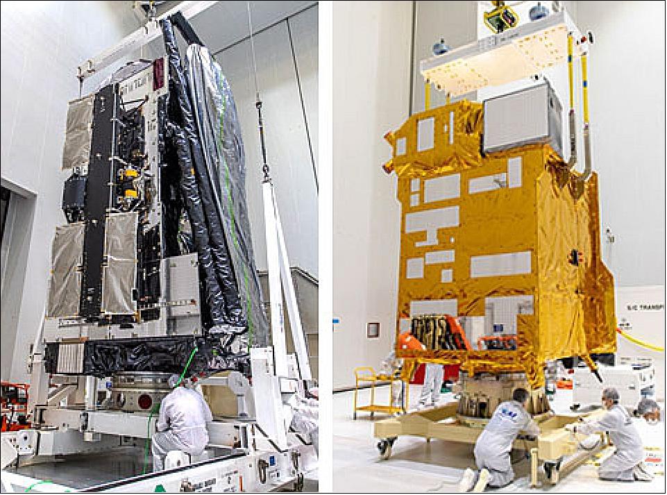
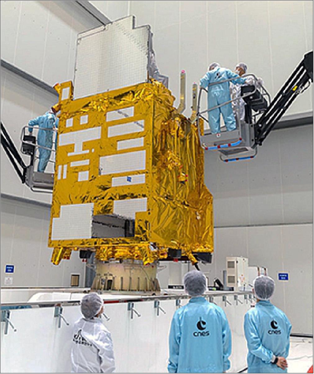
• January 27, 2020: The two satellite passengers for Arianespace’s next Ariane 5 mission – scheduled for liftoff on 18 February – are advancing through their pre-flight preparations during parallel activity in French Guiana. 9) Riding in the upper position of Ariane 5’s dual-payload dispenser system will be JCSAT-17. This is a telecommunications satellite for SKY Perfect JSAT Corporation, built by Lockheed Martin. Based on the A2100 platform, the spacecraft’s main coverage zone will be Eastern Asia, including Japan. South Korea’s GEO-KOMPSAT-2B – produced by the Korea Aerospace Research Institute (KARI) – will be deployed as the mission’s second passenger from Ariane 5’s lower payload position. Once in orbit, it will be used primarily for ocean and Earth environmental monitoring. Both spacecraft, which will be deployed in geostationary transfer orbit (GTO) during the Arianespace mission, are undergoing their preparation activity in the Spaceport’s S5 payload processing facility.
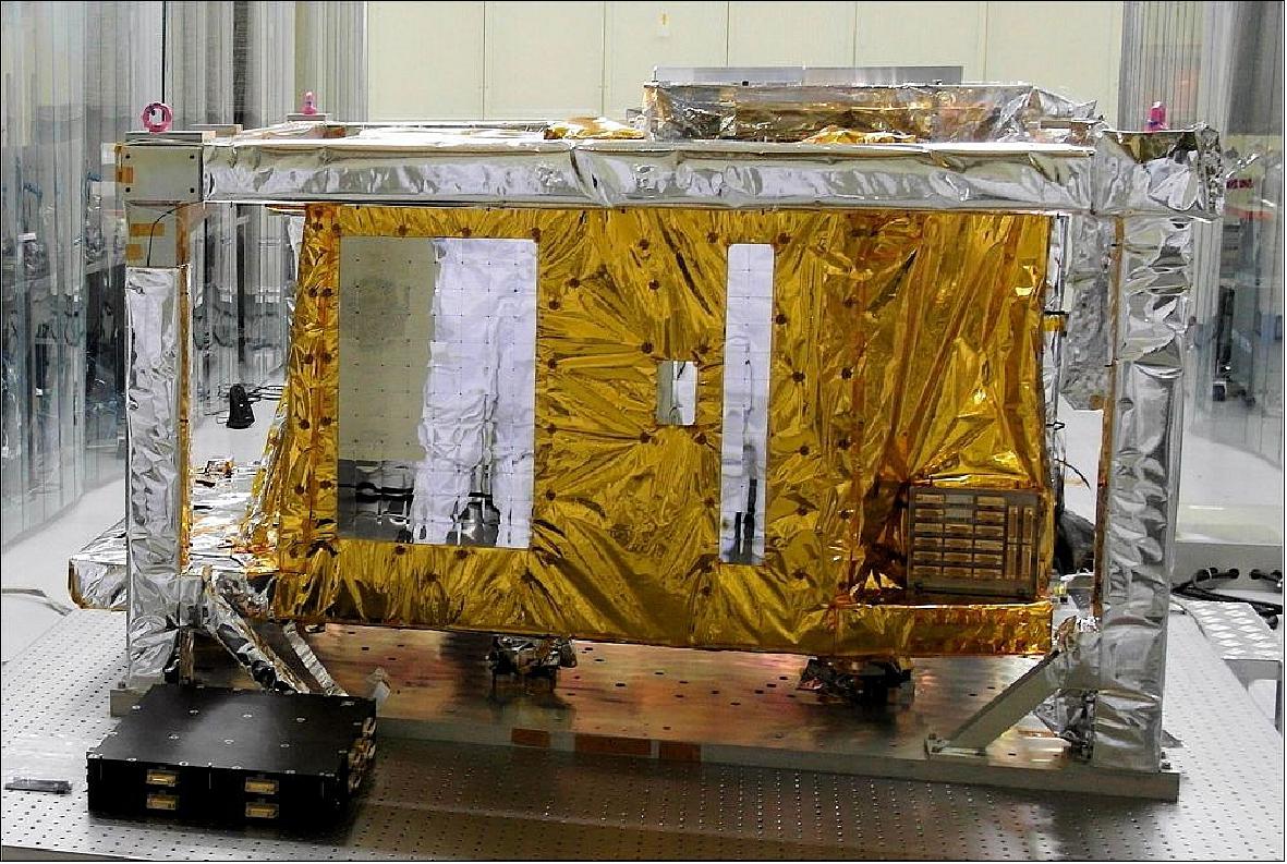
• December 20, 2017: After four months at the KARI (Korean Aerospace Research Institute) test facilities in Daejeon, South Korea, during which intensive testing was performed by a joint team of KARI and Airbus Defence and Space, the GOCI-II ocean colour imaging instrument has been delivered to the customer. 11) GOCI-II will be mounted on the GK2B satellite and will be launched in 2019 from Kourou on an Ariane 5. From its geostationary orbit, GOCI-II will analyse the colour of the ocean around the Korean peninsula, in order to detect, monitor, quantify and predict short-term variations in the characteristics of the coastal regions, for scientific and industrial purposes.
• June 21, 2017: The Harris-built AMI (Advanced Meteorological Imager) was delivered to KARI (Korea Aerospace Research Institute) and will be integrated into the next-generation GEO-KOMPSAT-2A weather satellite, scheduled to launch in 2018. 12)Highlights of AMI are that it provides three times more data, four times the resolution, than current capability, improves weather forecasting to help save lives and property and marks the third advanced imager sold internationally.
• April 18, 2017: TAS (Thales Alenia Space) of Madrid, Spain has sent South Korea the third of three panels that make up the communications payloads on the two GEO-KOMPSAT-2 satellites being built by KARI (Korea Aerospace Research Institute). This last panel will be integrated in the GK-2B satellite, and follows the two panels already delivered by the company at the end of last year for the GK-2A satellite. 13)Thales Alenia Space integrated and tested three communication panels in its plant in Spain, two for GK2A and one for GK2B. These panels house the subsystems that transmit to Earth the raw data from the instruments, as well as a communications payload comprising two repeaters, used to retransmit processed data to end-users. Thales Alenia Space and the South Korean company Qnion teamed up to develop RF (RadioFrequency) filters as part of the COACH (Co-development for Advanced Channel Filters) program, co-financed by CDTI (Spain’s Center for Industrial Technology Development) and KIAT (Korea Institute for Advancement of Technology). This program, completed on March 31, was instrumental in the development of several components and subassemblies used in the communications systems on GK2A and GK2B.
• January, 2016: CDR for GK2B completed
• February, 2016: Functional verification is being done at ETB (Electric Test Bed) and STM (Structure Thermal Model) qualification was completed.
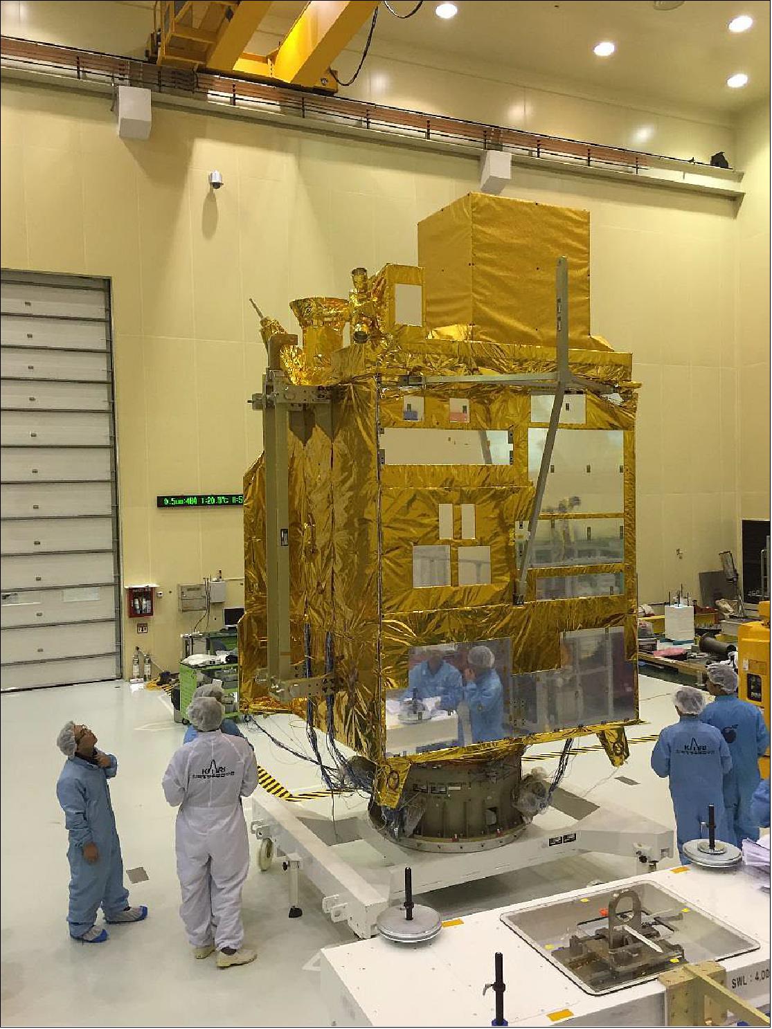
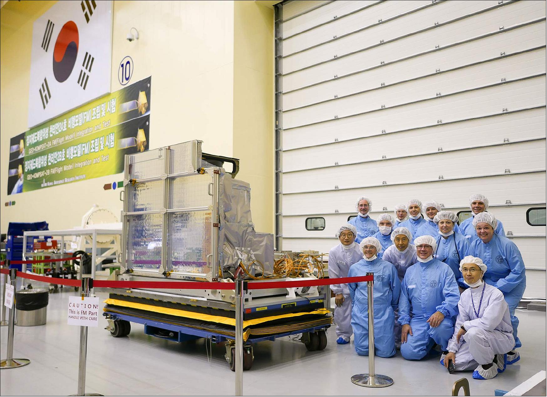
• May, 2016: GK2A FM (Flight Model) integration and Test started.
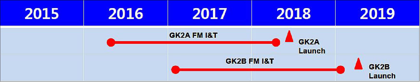
• Septmeber, 2015: CDR for GK2A completed
Launch
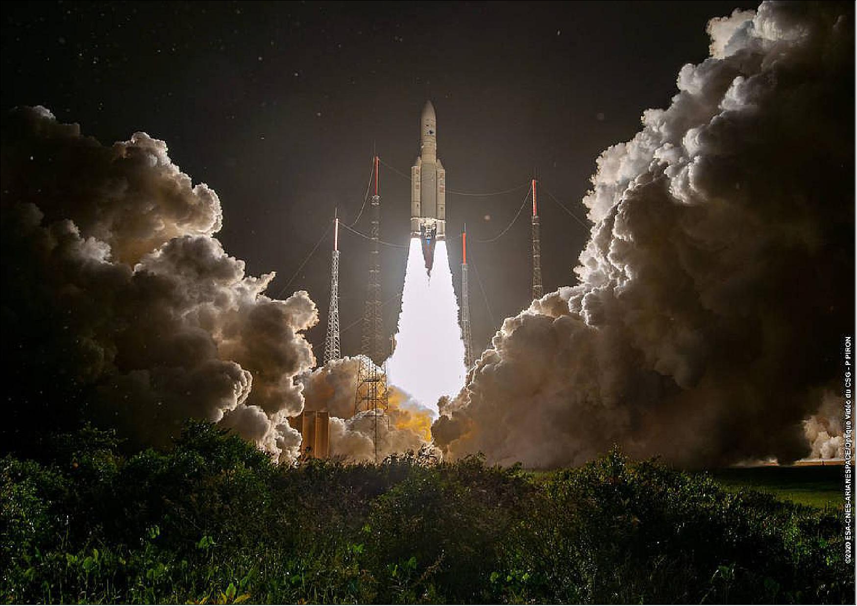
The GK-2A (GEO-KOMPSAT-2A) of KARI, along with the GSAT-11 communication satellite of ISRO were launched on 04 December 2018 (20:37 UTC) on an Ariane-5 ECA vehicle from Europe’s Spaceport in Kourou. The flight is designated VA246 in Arianespace terminology. 14) 15) 16) 17) 18)
GEO-KOMPSAT-2A, owned and operated by KARI ( Korea Aerospace Research Institute), provides meteorological and space weather monitoring over the Asia-Pacific region. The satellite has a design life of more than 10 years.
The GK-2B (GEO-KOMPSAT-2B) ocean monitoring satellite of KARI, along with the JCSAT-17 communication satellite of Japan's SKY Perfect JSAT corporation, were launched on 18 February 2020 (22:18 UTC) on an Ariane-5 ECA vehicle from Kourou. The flight was designated VA252 in Arianespace terminology. 19)
Orbit: Geostationary orbit over equator, mean altitude of 35786 km, inclination = 0º.
• Longitude of GEO-KOMPSAT-2A: 128.2ºE
• Longitude of GEO-KOMPSAT-2B: 128.0ºE.
GEMS is a sister instrument to NASA's TEMPO (Tropospheric Emissions: Monitoring of Pollution). GEMS will be the first satellite instrument in a constellation of three satellite instruments that will revolutionise the way scientists observe air quality over significant swaths of the Northern Hemisphere. GEMS will monitor atmospheric gases over Asia hourly during daytime from a geostationary, or fixed, orbit over the equator. This marks a significant leap forward in scientists' ability to monitor air pollution from space. 20)
GEMS is nearly identical to TEMPO, which is scheduled to launch into geostationary orbit in 2022 as a payload on Intelsat 40e. TEMPO will make hourly daytime measurements of air quality over North America. Both GEMS and TEMPO were built by Ball Aerospace in Boulder, Colorado. The European Space Agency's Sentinel-4, currently in development, will observe air quality over Europe.
All three instruments will provide data products that will improve scientists' ability to understand and forecast air quality around the Northern Hemisphere.
Mission Status
• October 8, 2020: The Ministry of Science and ICT (MSIT), Ministry of Oceans and Fisheries (MOF), and Ministry of Environment (MOE) announced that they would begin the standard marine image service provided by Cheollian 2B satellite through the Korea Hydrographic and Oceanographic Agency (KHOA) on October 5. 21) MOF provides marine image data (pre-processing standard data, Level 1) produced for the general public to view through the KHOA website (www.khoa.go.kr) easily. The data can be used by municipal administrations to cope with marine disasters related to red tide and oil spills, by agencies to support and manage fishing activities such as fishery search, and by marine research institutes. Beginning in 2021, there were plans to integrate marine data, such as the wide-area distribution of marine waste and the migration path of Sargassum horneri, into map-based services and continue to expand the services utilising satellite information. In the future, it will also provide satellite information services to cope with marine issues such as red tide and oil pollution detection. The public can receive marine image data (pre-processing standard data) from the Cheollian 2B satellite free of charge through the KHOA website beginning today, and 26 types of data will be serviced from January next year.
• May 25, 2020: First Release of the Ocean Color Images of the Seas around the Korean Peninsula taken by Cheollian 2B. Successful reception of the first ocean colour images from Cheollian-2B 22) The Ministry of Science and ICT (MSIT) and the Ministry of Oceans and Fisheries (MOF) announced the first release of the ocean colour images taken by the GEO-KOMPSAT-2B satellite (Cheollian 2B, 3.4-ton class).
- Cheollian 2B conducted two performance tests of the GOCI-II (Geostationary Ocean Color Imager II) payload on March 23 and April 21-22. Though the payload is still undergoing the calibration phase, the first ocean colour images of Korea as well as other parts of Northeast Asia and the surrounding sea area were seen to be very clear thereby demonstrating the excellent performance of Cheollian 2B. Cheollian offers a spatial resolution (500 m x 250 m) four times better than its predecessor, Cheollian 1, providing clearer images for marine observation. With four additional observation bands, it can swiftly gather diverse marine data, including information on port and coastal facilities, water quality changes, and oil spills detection. These bands cover a range of optical wavelengths, offering insights into marine pollutants, chlorophyll concentrations, suspended matter, and vegetation.
- The GOCI-II payload of Cheollian 2B will go through fine adjustments and calibration for optimisation of the payload until it begins normal services through the Korea Ocean Satellite Center (KOSC) in October this year. It is expected to achieve its performance target without difficulty. The GEMS (Geostationary Environment Monitoring Spectrometer) payload is also undergoing preparations to deliver observation images using hyperspectral information with all operations proceeding nominally as originally scheduled. The GEMS payload is the world’s first hyperspectral imager to operate in the geostationary orbit, requiring a longer time for testing and validation compared to the GOCI-II payload for which KOSC already has prior operational experience. The Ministry of Environment plans to complete software development for the calibration of hyperspectral observation data in May and begin the testing and validation of the observation data product in June and release the first atmospheric environment image around October.
• February 19, 2020: The Geostationary Environment Monitoring Spectrometer (GEMS) instrument, jointly developed by Ball Aerospace and Korea Aerospace Research Institute (KARI) under the leadership of Ball Aerospace, launched successfully on 18 February 2020. GEMS was integrated onto KARI's GEO-KOMPSAT-2B satellite. 23) Once operational in space, GEMS will be the first air quality sensor in geostationary orbit where it will help monitor pollution events in the Korean peninsula and Asia-Pacific region.
• February 11, 2020: The NMSC (National Meteorological Satellite Center) of KMA is providing a GK-2A online image product service on the following link: http://nmsc.kma.go.kr/enhome/html/satellite/viewer/selectGk2aSatViewer.do?view=basic#none 24)
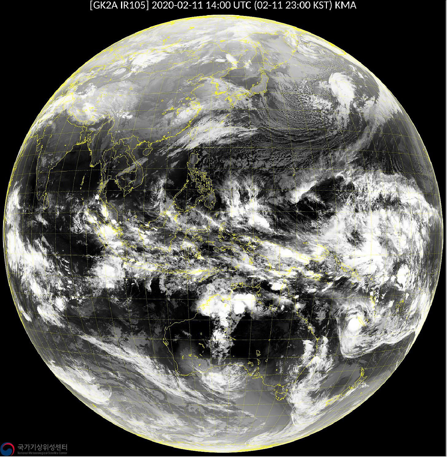
• July 25, 2019: The Geo-KOMPSAT-2A geostationary meteorological satellite, managed by the Korea Meteorological Administration (KMA), began operation at 00 UTC on 25 July 2019, continuing the COMS (Communication, Ocean and Meteorological Satellite) mission of strengthening Korea’s capability to monitor the atmospheric environment over the Asia-Pacific region. Geo-KOMPSAT-2A data and images are now available through the NMSC webpage. Start of the GK-2A official operation was on 31 July 2019. 25)
• January, 2019: The GK-2A satellite was in the early commissioning phase after launch. 26)
Sensor Complement
The following sensor complements were selected for the two GEO-KOMPSAT-2 missions: 27) 28) 29) 30)
1) GEO-KOMPSAT-2A mission (meteorological / space weather sensors). The main purpose of GEO-KOMPSAT-2A is meteorological remote sensing. Sensor complement:
• AMI (Advanced Meteorological Imager), formerly known as MI-II (Meteorological Imager-II)
• KSEM (Korean Space Environment Monitor)
2) GEO-KOMPSAT-2B (ocean / environmental sensors), a launch is scheduled for 2019. Sensor complement:
• GOCI-II (Global Ocean Color Imager-II)
• GEMS (Geostationary Environment Monitoring Spectrometer).
Parameter | AMI (ABI heritage) | GOCI-II | GEMS |
Spectral range | 0.47 µm-13.3 µm | 380-900 nm | 300-500 nm |
Spatial resolution | 500 m, 1 km(VIS), 2 km(IR) | 300 m | 7.0 km |
Spectral resolution | 400~1,000 nm | 10~40 nm, 500 nm | 0.8 nm |
No of bands | 16 | 13 | Hyperspectral |
Coverage | FD, NHFD, North-East Asia, Korea Peninsula (LA) | 2,500 x 2,500 km(LA), FD | FD, NHFD, North-East Asia, Korea Peninsula (LA) |
Observation period | FD 4 times/hour | 10 times/day | 8 times/day |
Observation time | FD 15 min, NHFD 5 min, | < 30 minutes (LA) | 30 minutes |
Ensuring the GK2 system development under KARI’s responsibility (Ref. 6)
• The development of GK2 Satellite system is KARI’s responsibility. This is the 1st attempt of KARI for Geostationary satellite.
• The GK2 payloads are acquired by Procurement (AMI), Joint development (GOCI-2, GEMS) and Domestic development (KSEM) through international/domestic competition.
• System level Integration & Test will be done by KARI using KARI facilities:
- Required EGSE are newly developed
- Some MGSE of COMS are reused and others are newly developed
- KARI accommodates payloads to platform and perform system test with the payload team support as necessary.
• Ground station will be developed by KARI and Korean industries.
AMI (Advanced Meteorological Imager)
The requirements of AMI call for:
• Multi-channel observation capability: 16 channels (4 VIS and 12 infrared)
• High spatial resolution: 0.5-1.0 km for VIS and 2 km for the infrared channels
• Fast imaging: within 10 minutes for FD (Full Disk) observations
• Flexibility for the regional area selection and scheduling.
In April 2013, KARI awarded a contract to ITT Exelis of Rochester, N.Y., USA (Harris Corporation as of 2015) to provide Korea an advanced geostationary weather imager to support the country’s forecasting capabilities. Under the GEO-KOMPSAT-2A program, Exelis will deliver AMI (Advanced Meteorological Imager), which is based on the ABI (Advanced Baseline Imager) to be flown on the next-generation NASA/NOAA GOES-R (Geostationary Operational Environmental Satellite-R) series. In fact, ITT Exelis has or will design and develop all instruments (AMI, ABI,AHI and MI) listed in Table 2. 31)
AMI of GK-2A will have sixteen spectral bands (Table 2) which are slightly different from ABI of GOES-R and AHI (Advanced Himawari Imager) of Himawari-8/9, and will provide three times more spectral information, four times the spatial resolution, and more than four times faster temporal coverage than the current MI (Meteorological Imager) of COMS.
AMI of GK-2A has a mass of 338 kg, a power consumption of 450 W, and a data rate of 66 Mbit/s.
Channel No | Channel | AMI (µm) | ABI (µm) | AHI (µm) | MI (µm) |
1 | VIS (blue) | 0.470 | 0.470 | 0.46 |
|
2 | VIS (green) | 0.511 |
| 0.51 |
|
3 | VIS (red) | 0.640 | 0.640 | 0.64 | 0.675 |
4 | VNIR | 0.865 | 0.865 | 0.86 |
|
5 | SWIR | 1.380 | 1.378 |
|
|
6 | SWIR | 1.610 | 1.610 | 1.6 |
|
|
|
| 2.250 | 2.3 |
|
7 | MWIR | 3.830 | 3.90 | 3.9 | 3.75 |
8 | MWIR (WV) | 6.241 | 6.185 | 6.2 |
|
9 | MWIR (WV) | 6.952 | 6.95 | 7.0 | 6.75 |
10 | MWIR (WV) | 7.344 | 7.34 | 7.3 |
|
11 | TIR | 8.592 | 8.50 | 8.6 |
|
12 | TIR | 9.625 | 9.61 | 9.6 |
|
13 | TIR | 10.403 | 10.35 | 10.4 | 10.8 |
14 | TIR | 11.212 | 11.20 | 11.2 |
|
15 | TIR | 12.364 | 12.30 | 12.3 | 12.0 |
16 | TIR | 13.31 | 13.30 | 13.3 |
|
AMI of GK-2A is designed to have an improved spectral, temporal, and spatial resolution compared to the first generation imager. For example, the number of channels will be increased at least threefold (from 5 to 16) while the spatial resolution will be 2 km for the 10 infrared channels and 1 km for 6 visible channels (only channel No 3 will have a resolution of 0.5 km). Furthermore, the time required to scan a full disk will be reduced to about one-fifth of the current 28 minutes. With these improvements, many of new value-added products are expected to be produced, in addition to the significant improvement of the current 16 products.
Among the new products, atmospheric instability information is one of the important new possibilities with the pseudo-sounding capability of AMI. Although its accuracy is expected to be limited due to the limited number of sounding channels, its high spatial and temporal resolution could provide a significant addition for the nowcasting applications.
In May 2015, KARI completed a multi-disciplinary design review of the AMI ( Advanced Meteorological Imager) and determined the team is ready to begin final production. KARI’s review focused on the AMI and spacecraft interfaces and mission requirements. 33)
Bands | Nadir resolution | SNR (min) | NEDT (max) | MTF (Modulation Transfer Function) | Dynamic range | |||||
@ 240 K | @ 300 K | 1/4 | 1/2 | 3/4 | 4/4 | |||||
VNIR | VSI0.4 | 1 km | 261 | - | 0.85 | 0.73 | 0.53 | 0.32 | 0~720W/m2/sr/µm | |
VSI0.5 | 1 km | 299 | - | 0.84 | 0.65 | 0.41 | 0.22 | 0~710W/m2/sr/µm | ||
VSI0.6 | 0,5 km | 130 | - | 0.83 | 0.59 | 0.37 | 0.19 | 0~620W/m2/sr/µm | ||
VSI0.8 | 1 km | 300 | - | 0.86 | 0.64 | 0.40 | 0.20 | 0~320W/m2/sr/µm | ||
NIR1.3 | 2 km | 300 | - | 0.90 | 0.73 | 0.53 | 0.32 | 0~114W/m2/sr/µm | ||
NIR1.6 | 2 km | 300 | - | 0.90 | 0.73 | 0.39 | 0.32 | 0~77W/m2/sr/µm | ||
MWIR | IR3.8 | 2 km | - | 2.7 K | 0.18 K | 0.84 | 0.62 | 0.39 | 0.22 | 0~400 K |
IR6.3 | 2 km | - | 0.40 K | 0.10 K | 0.83 | 0.62 | 0.39 | 0.22 | 0~300 K | |
IR6.9 | 2 km | - | 0.37 K | 0.10 K | 0.81 | 0.62 | 0.39 | 0.22 | 0~300 K | |
IR7.3 | 2 km | - | 0.32 K | 0.10 K | 0.81 | 0.62 | 0.39 | 0.22 | 0~320 K | |
IR8.7 | 2 km | - | 0.27 K | 0.10 K | 0.83 | 0.62 | 0.39 | 0.22 | 0~330 K | |
LWIR | IR9.6 | 2 km | - | 0.22 K | 0.10 K | 0.82 | 0.61 | 0.39 | 0.22 | 0~300 K |
IR10.5 | 2 km | - | 0.21 K | 0.10 K | 0.80 | 0.60 | 0.39 | 0.22 | 0~330 K | |
IR11.2 | 2 km | - | 0.19 K | 0.10 K | 0.80 | 0.59 | 0.39 | 0.22 | 0~330 K | |
IR12.3 | 2 km | - | 0.26 K | 0.12 K | 0.79 | 0.57 | 0.38 | 0.22 | 0~330 K | |
IR13.3 | 2 km | - | 0.48 K | 0.30 K | 0.78 | 0.56 | 0.37 | 0.20 | 0~305 K | |
Parameter | GK-2A AMI (Advanced Meteorological Imager) | COMS MI (Meteorological Imager) |
Spectral bands | 16 channels (4 VIS, 2 NIR, 10IR) | 5 channels ((1 VIS, 4 IR) |
Spectral resolution | 0.64 µm: 0.5 km | 0.675 µm: 1 km |
Observation duration | Full disk: ≤10 minutes | Full disk: ≤30 minutes |
On-board calibration | Visible: Solar Diffuser |
|
FOV (Field of View) | 0.9º x 1.9º; Large NS (North-South) FOV: Slower Scan Rate, Higher SNR |
FOR (Field of Regard) | 22º ((i.e. ±11º) |
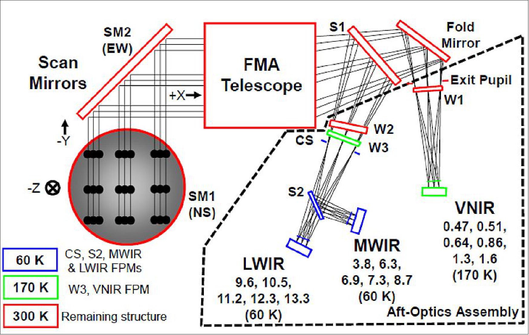
Two scan mirrors | (NS, EW), SiC with silver coating; Lower inertia and power; Less disturbance |
Two beam-splitters(S1,S2) | S1 for VNIR; S2 for MWIR/LWIR |
FMA (Four Mirror Anastigmatic) telescope | Aperture = 270 mm; Collecting sufficient photons for good SNR |
AMI On-Board Calibration in the IR Bands
• 3-bounce ICT (Internal Calibration Target)
• Robust against stray-light and contamination
• Very high Emissivity : 0.995
• Accommodated in anti-nadir location
- Observe the black body target at the start of every operational timeline iteration.
AMI On-Board Calibration in the Visible Bands
• Solar calibration target : Spectralon®Diffuser
• Solar calibration cover open only when calibrating
- Solar calibration can occur any day of the year at 6:00~6:15 hours (spacecraft local time).
AMI Development Status
• EDC (Effective Date of Contract) : February 18 2013 (completed)
• Kick-off Meeting : April 10, 2013 (completed)
• SRR (System Requirement Review) Meeting : October 23, 2013 (completed)
• PDR (Preliminary Design Review) Meeting : April 8, 2014 (completed)
• CDR (Critical Design Review)/EQSR Meeting : March 2-3, 2015 (completed)
• TRR (Test Readiness Review) Meeting : February 2016
• PER (Pre-Environmental Review) Meeting : April 2016
• PSR (Pre-Sip Review) Meeting : January 2017
• AMI Delivery : March 2017
KSEM (Korean Space Environment Monitor)
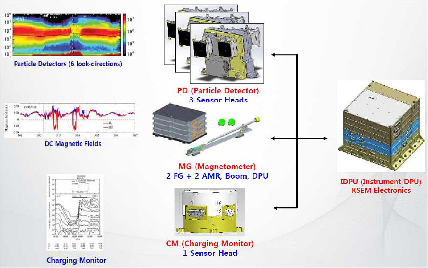
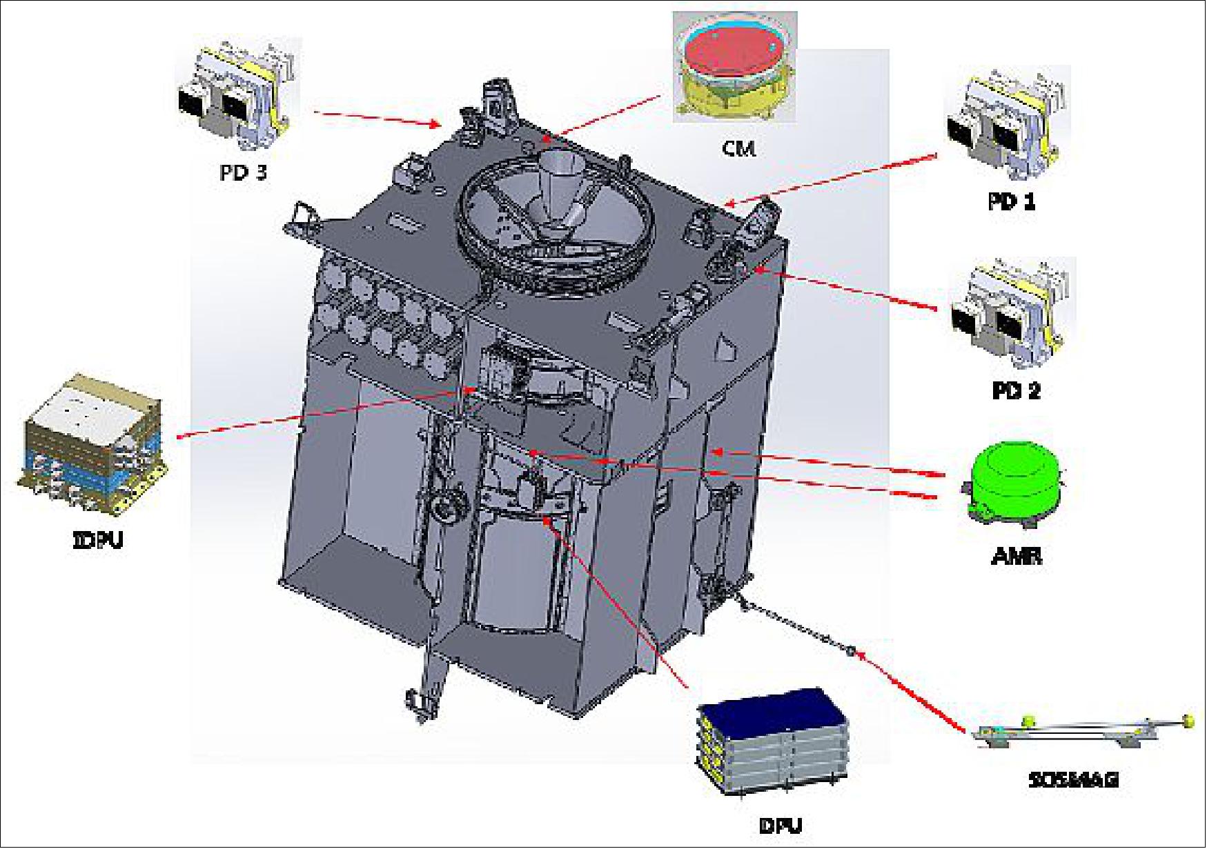
KMA in coordination with KARI selected KHU (Kyunghee University) of Seoulto develop the KSEM suite of instruments and post-delivery support for the assembly and integration test, pre- and post- launch test of Geo-KOMPSAT-2A. The suite of KSEM instruments consists of particle detector (PD); magnetometer (MAG); and SCM (Satellite Charging Monitor). The sensors are used to monitor the space environment 6 the severe space weather information of high-impact space storms, the radiation environment hazardous to spacecraft, aircraft and radio communication for 24 hours/7 days. 34) 35)
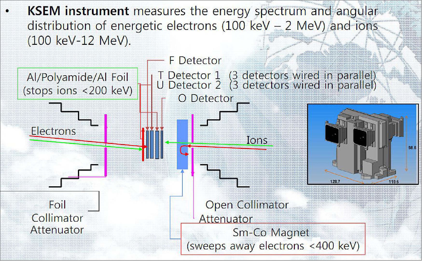
• PD (Particle Detector): The PD is of THEMIS SST (NASA) heritage. It consists of 3 detector heads and measures the differential energy flux of electrons and ions within the energy range of 100 keV and 2 MeV, which are trapped within Earth’s magnetic field.
• MAG, of THEMIS FGM (FluxGate Magnetometer) heritage, measures three components of near Earth magnetic field within the range of ±350 nT and monitors those variations caused by space storm and high-speed stream.
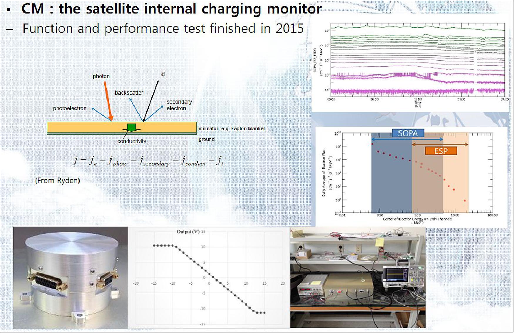
• SCM (also referred to as CM) measures the satellite internal charging current within the range of ±3 pA/cm2 due to high energy particles and provides advance warning of a possible electrical discharge.
KSEM is the first Korean space weather instrument suite aboard a GEO satellite. Like the Galaxy 15 anomaly on 2010, GEO satellites are easily exposed to the risk due to severe space weather. It is expected that KSEM data will contribute to secure the satellite operation and the high-tech ground infrastructure.
Sensor | Parameter | Requirement | Specification (after CDR) |
PD (Particle Detector) | Energy range | 100 keV ≤ E ≤ 2 MeV | 100 keV ≤ E ≤ 2 MeV |
Energy resolution | ΔE/E ≤ 30% | ΔE/E ≤ 30% | |
Time resolution | ≤ 0.33 s | ≤ 0.33 s | |
View direction | 5-directions | 6-directions | |
Geometric factor | ≥10-3 (cm2 sr) | ≥10-2 (cm2 sr) | |
Background contamination | ≤3% | ≤3% | |
Count resolution | ≥8 bit | 8 bit | |
MAG (Magnetometer) | Range | -350 nT to +350 nT (3-axis) | Variable up to ± 64,000 nT |
Accuracy | ≤1 nT | ≤1 nT | |
Time resolution | ≤0.1 s | 0.1 s | |
Type | Non-deployable | Deployable | |
SCM (Satellite Charging Monitor) | Range | -3 pA/cm2 to +3 pA/cm2 | -3 pA/cm2 to +3 pA/cm2 |
Accuracy | ≤0.01 pA/cm2 | ≤0.01 pA/cm2 | |
Time resolution | ≤1 s | ≤1 s |
SOSMAG (Service Oriented Spacecraft Magnetometer)
Monitoring the solar wind conditions, in particular its magnetic field (interplanetary magnetic field) ahead of the Earth is essential in performing accurate and reliable space weather forecasting. The magnetic condition of the spacecraft itself is a key parameter for the successful performance of the magnetometer onboard. In practice a condition with negligible magnetic field of the spacecraft cannot always be fulfilled and magnetic sources on the spacecraft interfere with the natural magnetic field measured by the space magnetometer. 36)
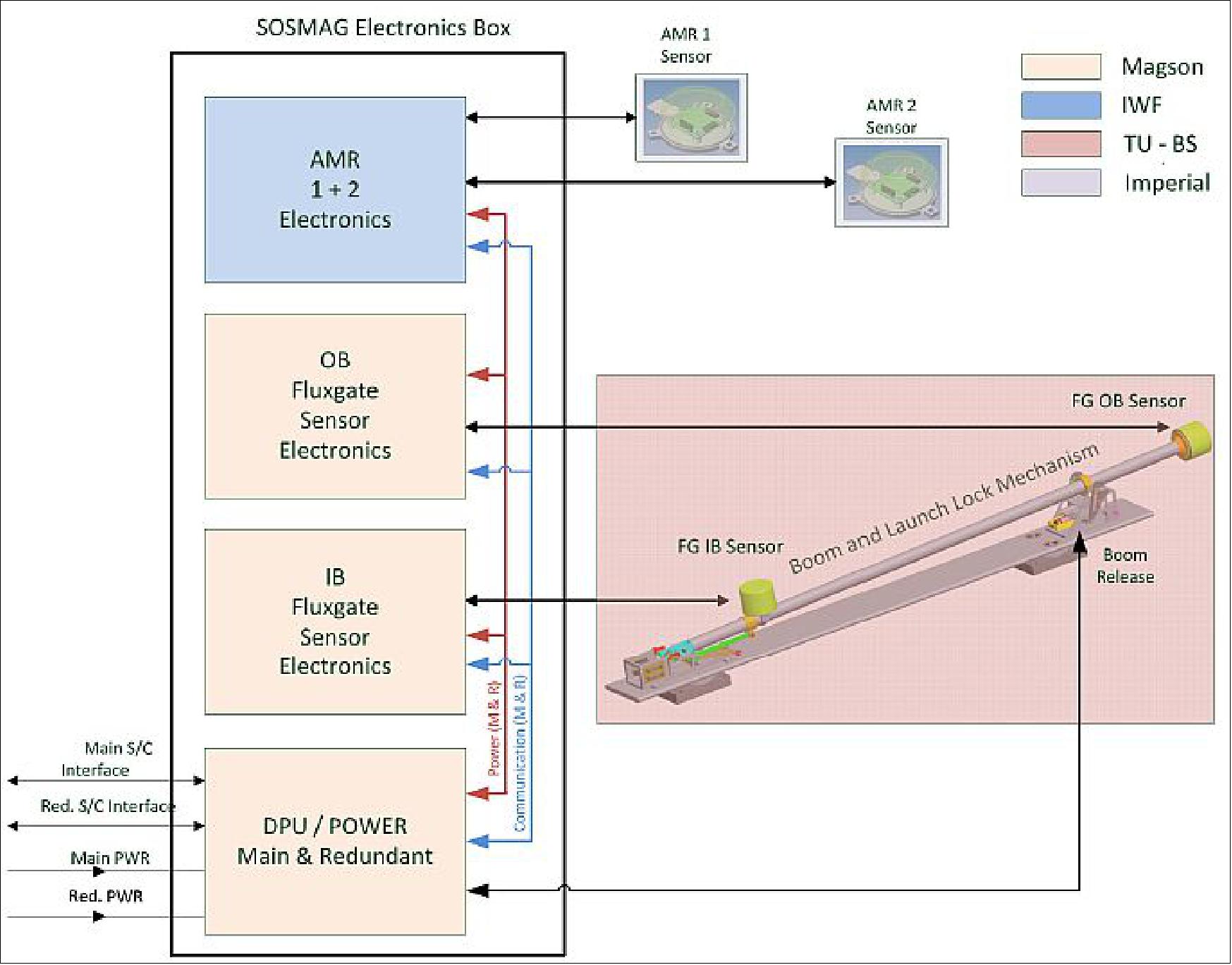
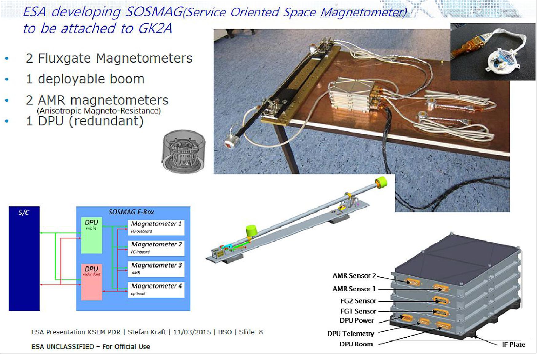
The "ready-to-use" SOSMAG (Service Oriented Spacecraft Magnetometer) is developed for use on any satellite implemented without magnetic cleanliness programme. It enables detection of the spacecraft field AC variations on a proper time scale suitable to distinguish the magnetic field variations relevant to space weather phenomena, such as sudden increase in the interplanetary field or southward turning. This is achieved through the use of dual fluxgate magnetometers on a short boom (1m) and two additional AMR (Anisotropic Magneto-Resistance) sensors on the spacecraft body, which monitor potential AC disturbers. The measurements of the latter sensors enable an automated correction of the AC signal contributions from the spacecraft in the final magnetic vector. After successful development and test of the EQM prototype, a FM (Flight Model) is being built for the Korean satellite Geo-Kompsat 2A.
SOSMAG has the following basic features:
1) 2 fluxgate sensors (FG) on a short boom -the inboard (IB) and outboard (OB) sensor
2) 2 AMR sensors on spacecraft body
3) deployable boom of 1m length
4) a mounting interface for the boom, without specific requirements on the spacecraft structure
5) and the associated electronics.
Mass budget: sensor and electronics 2.0 kg; mounting plate and boom 1.1 kg. Power budget: 2.6 W.
All four sensors are operated continuously and simultaneously with a time resolution of at least 1 Hz or higher, depending on the type of effect to be characterised.
The operation shall be continuous and with higher time resolution in the early stages (commissioning phase) of the spacecraft flight, such that the typical operations of spacecraft subsystems and instruments are closely monitored and characterised in detail. The data of this early phase are studied on ground to detect and characterise the spacecraft AC effects and to determine correction factors for each specific AC disturbance. The correction factors are implemented in inflight algorithms, which then enable automated correction for these AC effects during further flight operation.
Advantages of SOSMAG:
For SOSMAG, the key point is that the use of 2 sensors on a boom but with 2 additional sensors on the spacecraft body, which monitor important AC disturbers, allows a considerable reduction of the boom length (estimated factor ~3 compared to conventional systems). The advantage of these additional spacecraft sensors is demonstrated here in the functionality test with the spacecraft mockup.
The experience from the Venus Express spacecraft with only two sensors (2 sensors on 1 m boom and no magnetic cleanliness for the spacecraft) showed that correction for AC disturbers is difficult. As long as spacecraft disturbers are only switched on/off, their effect may be identified from the difference of the measurements at the boom sensors. Yet the detection of all the "jumps" and precise determination of their respective amplitude, due to switching events during the whole flight, was a cumbersome task, even when semiautomated after a learning phase. It was also difficult to separate simultaneously active AC sources, due to their overlapping effect in the data. The correction for AC disturbers with a changing character needed a specific procedure; the correction for the AC effects of the Solar Array Drive Motors (SADAM) required permanently the housekeeping data from the spacecraft. The finally achieved precision was ± nT per component on DC level. 37)
Now with SOSMAG, two additional sensors are mounted on the spacecraft to monitor specific AC sources. These sensors are intended to measure mainly the signature of a single source or eventually a few sources together located near the sensor. This allows to clearly correlate their signal at that spacecraft sensor with the signal measured at the outboard boom sensor in a learning phase, where the individual AC disturbers are characterised and the correction factors determined. This is possible also for non-linear effects of the AC source, e.g. the motor in the mockup test-sequence. Later on during the spacecraft flight, the correction can be performed automatically with weighed subtractions; it is not necessary to detect and process each individual AC variation during flight. The achievable accuracy on AC level is ± 0.1 nT, which is appropriate to study space weather phenomena and to allow space weather forecast for Earth.
The main advantage of SOSMAG is, that no requirements of magnetic cleanliness are posed on the spacecraft. The effort of mounting the base plate with the boom and accommodation of two additional sensors on the spacecraft body is far lower than for any magnetic cleanliness program. Furthermore, it is known from scientific spacecraft missions, e.g. Cluster (ESA), MMS (NASA), Venus Express (ESA), Mars Express (ESA), that not the constant or slowly varying DC magnetic level is the main problem for the accuracy of the data, but the continuously occurring AC effects during flight (up to ~ 1000 per day), due to switching events, motors etc. The effect of induced spacecraft fields can generally be neglected in the low space field environment of interest.
The SOSMAG magnetometer system allows for an automated removal of AC effects during the spacecraft flight, thus solving the main problem of the dataaccuracy for space weather observation. In practice, any spacecraft on a suitable orbit for space weather monitoring could be equipped with a ready-to-go SOSMAG magnetometer package, increasing the availability of data required for eventual space weather alerts.
Flight model for GEO-KOMPSAT-2A:
KARI in cooperation with the KHU (Kyung Hee University) in Seoul is developing a satellite GEO-KOMPSAT-2A for meteorological observations, in geostationary orbit located 128.2° East. Space weather observation will be performed by the KSEM (Korean Space Environment Monitor) developed by KHU, with particle detectors, a charging monitor and a magnetometer. The SOSMAG system (when in the EQM development phase) was chosen as a suitable ready-to-go instrument without imposing a requirement on magnetic cleanliness to the spacecraft.
The development of this specific flight model of SOSMAG is funded by ESA (European Space Agency) in the framework of the SWE (Space Weather Environment) of the ESA’s SSA (Space Situational Awareness) Program. 38)
The SOSMAG mounting plate with boom and two fluxgate sensors will be positioned on one side of the spacecraft; the two AMR sensors are located at selected positions near potential strong AC disturbers on the spacecraft body.
The flight model development with hardware and onboard software for the correction of the AC sources is ongoing. Delivery to KARI is foreseen for early 2017. After launch and a learning phase to determine the correction factors during the commissioning of the spacecraft, the automated correction will be standard procedure during the science phase of the spacecraft.
GEMS (Geostationary Environment Monitoring Spectrometer)
The Ministry of Environment (ME), Korea, is funding the GEMS instrument for atmospheric composition measurements in the Asia-Pacific region. Feasibility studies for the subsystem, system level and scientific missions had been finished. For the air quality mission, ME formally established the Global Environmental Satellite Program Office in June 2009 in NIER (National Institute of Environmental Research) of ME. 39)
GEMS will contribute to the understanding of the globalisation of pollution events, source/sink identification, and long-range transport of pollutants and SLCFs (Short-Lived Climate Forcers), as a part of the activities of the Atmospheric Composition Constellation under CEOS (Committee on Earth Observation Satellites). This Constellation coordination activity is focused on collaboration to improve and extend data utilisation from the planned missions. The missions now funded are: Korea (GEMS), Europe (Sentinel-4), and the US (TEMPO), will enable the “baseline” constellation data products.
Science Questions | Objectives |
• What are the temporal and spatial variations of concentrations and emissions of gases and aerosols that are important for air quality? | • To provide measurements of atmospheric chemistry, precursors of aerosols and ozone in particular, in high temporal and spatial resolution over Asia |
• How do regional and intercontinental transport affect local and regional air quality? | • To monitor regional transport events: transboundary pollution and Asian dust |
• How does air pollution drive climate forcing and how does climate change affect air quality? | • To quantify radiative forcing of aerosol and ozone and to monitor air quality for long term |
• How does meteorology affect the air quality ? | • To improve our understanding on interactions between atmospheric chemistry and meteorology |
• How can we quantify the outflow from Asia to cross Pacific ? | • To better understand the globalisation of tropospheric pollution |
• How can we improve the accuracy of air quality forecast using satellite measurements? | • To improve air quality forecast by constraining emission rates and assimilating chemical observation data |
In May 2013, KARI (Korea Aerospace Research Institute) awarded a contract to BATC (Ball Aerospace & Technologies Corporation) of Boulder, CO, USA to build the GEMS instrument for NIER (National Institute of Environmental Research) of the Ministry of Environment, Korea. 41)
GEMS is a geostationary scanning ultraviolet-visible spectrometer designed to monitor trans-boundary pollution events for the Korean peninsula and the Asia-Pacific region. The spectrometer provides high spatial and high temporal resolution measurements of ozone, its precursors, and aerosols. Hourly measurements by GEMS will improve early warnings for potentially dangerous pollution events and to support the monitoring of long-term climate change.
The GEMS instrument is the Asian element of a global air quality monitoring constellation of geostationary satellites that includes the TEMPO (Tropospheric Emissions: Monitoring of Pollution) spectrometer. Ball is the TEMPO instrument provider for NASA(LaRC (Langley Research Center) and the Harvard Smithsonian Astrophysical Observatory (SAO) on this EVI (Earth Venture Instrument) line program of NASA. TEMPO will be a hosted payload to be flown on a commercial geostationary satellite in the timeframe 2018/19. 42) 43) 44) 45)
Ball is building nearly identical geostationary ultraviolet visible spectrometers: TEMPO for NASA and GEMS for KARI. Both instruments will complete critical design in 2015 and be delivered in 2017. 46)
• TEMPO will be NASA's first UV-VIS spectrometer in GEO to make accurate observations of atmospheric pollution with high spatial and temporal resolution over North America, from Mexico City to the Canadian tar/oil sands, and from the Atlantic to the Pacific. TEMPO will provide hourly daylight measurements of ozone, nitrogen dioxide, sulfur dioxide, formaldehyde, glyoxal and other pollutants to create a revolutionary dataset that provides understanding and improves AQ (Air Quality) and climate forcing.
• The GEMS spectrometer is designed to monitor trans-boundary pollution events for the Korean peninsula and the Asia-Pacific region. The spectrometer provides high spatial and high temporal resolution measurements of ozone and its precursors. Hourly measurements by GEMS will improve early warnings for potentially dangerous pollution events and monitor long-term climate change. GEMS is manifested on the GEO-KOMPSAT-2B spacecraft.
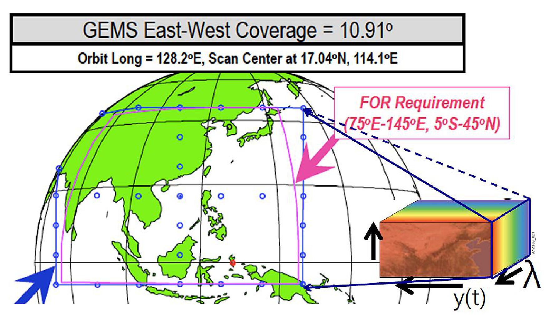
GEMS is expected to contribute monitoring air quality and SLCFs including ozone and aerosols in Asia in high temporal and spatial resolution. Using a scanning UV-Visible spectrometer, its observations can contribute to provide a set of tropospheric column products over the Asia-Pacific region at spatial resolution of ~ 8 km and temporal resolution of 1 hour. Other products include NO2, HCHO, SO2, and aerosol optical depth.
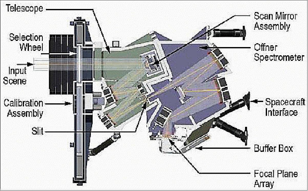
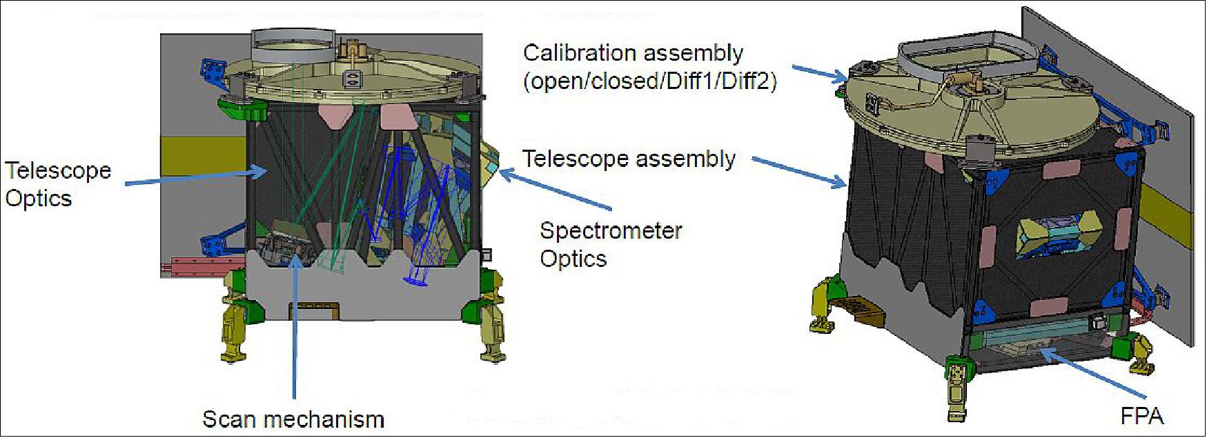
The GEMS instrument has a 2-axis scan mirror and a 1 k x 2 k focal plane array using a CCD (Charge Coupled Device) to image the ultraviolet/visible spectrum. GEMS will scan a 5000 km East/ West area in less than 30 minutes with state-of-the-art calibration and high spatial and spectral resolution. In geostationary orbit, GEMS will collect images over an 8 to 12 hour period.
Parameter | Requirement |
Design life, reliability | > 10 years after IOT (In-Orbit Test), > 0.85 @ 7 years |
FOR (Field of Regard) | > 5,000 km(N/S) x 5,000 km(E/W) N/S: 45ºN-5ºS, E/W: Selectable between 75ºE -145ºE |
Duty cycle/Imaging time | 8 images during daytime |
GSD (Ground Sampling Distance) | < 7 km(N/S) at Seoul GSD area < 56 km2 at Seoul (Aspect ratio shall be less than 1:3) |
Spectral range | 300 nm to 500 nm |
Spectral resolution | < 0.6 nm (hyperspectral) |
Spectral sampling | < 0.2 nm |
SNR (Signal-to-Noise Ratio) | > 720 @ 320 nm, > 1500 @ 430 nm |
Data quantisation | ≥ 12 bit |
MTF (Instrument level) | > 0.3 in N/S direction @ Nyquist frequency, > 0.3 in E/W direction @ Nyquist frequency |
Radiometric calibration accuracy | < 4% |
Spectral calibration accuracy | < 0.02 nm |
Polarisation factor | < 2% (310-500 nm), No inflection point within 20 nm for all wavelength ranges |
In February 2015, the GEMS instrument passed the CDR (Critical Design Review) which allowed the program to move into the manufacturing, assembly, integration and testing phase with instrument completion expected in early 2017. 47)
GEMS design features
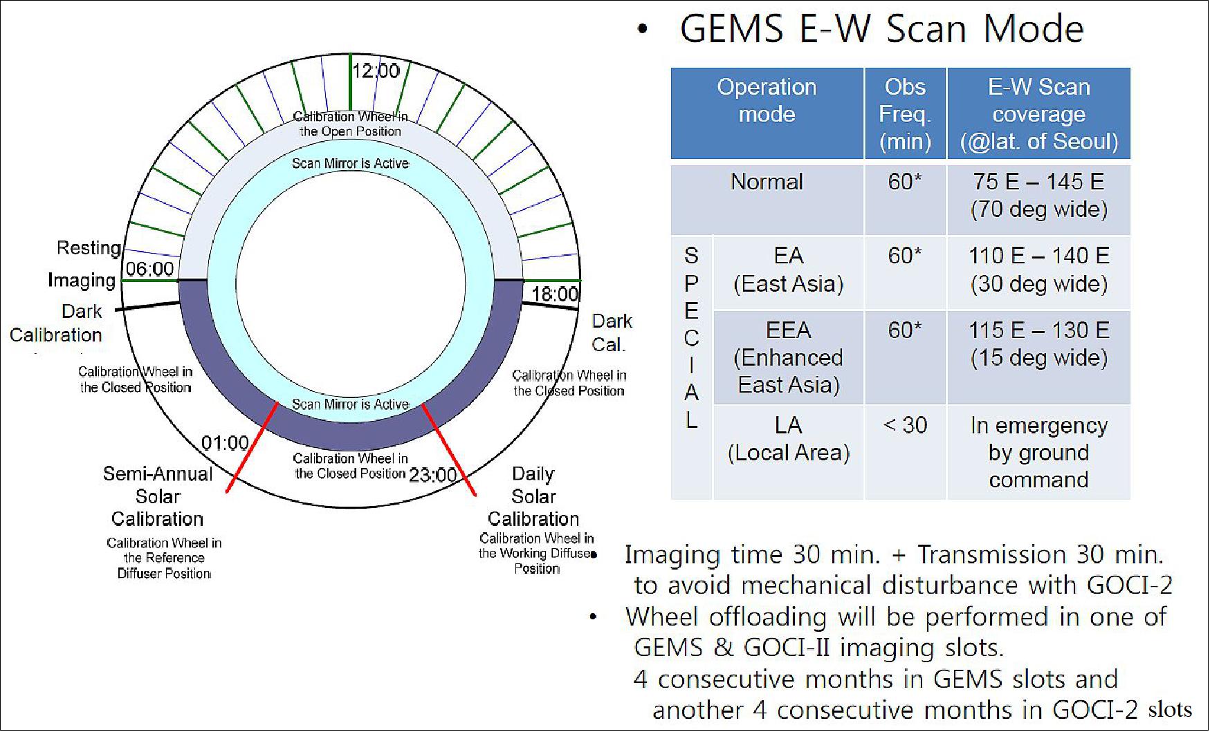
• Step-and-stare UV-Visible imaging spectrometer scanning at least 8 x per day in 30 minutes
• Daily solar and dark calibration
• Images coadded at each position + mirror move back < 30 minutes
- [ ~2 s @ each position (= coadding x image) + step & settle ] x ~700 position + ~2 s scan mirror back to null position
• Scanning Schmidt telescope and Offner spectrometer
• Diffusers for on-orbit solar calibration and onboard LED light source
• 2-axis scan mechanism with gyro feed capability
• Redundant electronics for 10-year lifetime
In summary:
• GEMS onboard the Geo-KOMPSAT-2B is expected to provide information on aerosol and O3 together with their precursors in high spatial and temporal resolution
- O3 NO2 HCHO SO2 AOD/AI/AEH, (possibly CHOCHO, BrO)
- Clouds, surface reflectance, UV radiation.
• The predicted performance of trace gases from the initial design of GEMS satisfies the product accuracy requirements of NO2, HCHO, O3. Meanwhile, the performance is expected to be poor in winter, in particular near Korea.
GOCI-II (Global Ocean Color Imager-II)
Korea established an independent national institute, KIOST (Korea Institute of Ocean Science & Technology), which is responsible for the definition of mission and user requirements and for the operation of GOCI-II. GOCI-II is the next-generation instrument of GOCI, one of the major payloads on COMS, the 1st ocean colour imager in the world operating in the geostationary orbit.
GOCI had been developed to provide a monitoring of ocean colour around the Korean Peninsula to detect, monitor, quantify, and predict short term changes of coastal ocean environment for marine science research and application purposes. As such, GOCI acquired only LA (Local Area) mode observations in an area of size 2500 x 2500 km. The requirements of GOCI-II call for two coverage modes: LA (Local Area) and FD (Full Disk) as illustrated in Figure 30.
In July 2013, KARI awarded a contract to Airbus Defence and Space (former EADS Astrium) to jointly design and manufacture the GOCI-II instrument for the future Korean mission GK-2B (GEO-KOMPSAT-2B), scheduled for launch in 2019. The GOCI-II instrument will be designed using the latest generation technologies developed by Airbus DS (former Astrium) for space applications, including a 7 Mpixel CMOS sensor, a silicon carbide telescope and a high-precision pointing mechanism. GOCI-II offers significant advances in comparison to GOCI: enhanced resolution (250 m), 12 spectral bands and daily coverage of full disk Earth data. 48) 49)
GOCI-II is being developed by the Joint Development Team, KARI, KIOST and Airbus DS. The contract signed with KARI also stipulates that six Korean engineers will help to develop the instrument at the Airbus Group site in Toulouse. Airbus Defence and Space has agreed to use South Korean industrial services amounting to 5% of the contract price. In addition, test resources made available by KARI at its Daejeon site in Korea will be used for environment testing.
• GOCI-II is focused on the coastal and global ocean environment monitoring with better spatial resolution and spectral performance for the succession and expansion of the mission of GOCI.
• The user requirements of GOCI-II will have higher spatial resolution, 300 m x 300 m, and 13 spectral bands to fulfill GOCI’s user requests, which could not be implemented on GOCI for technical reasons.
• GOCI-II will have a new capability, supporting user-definable observation requests such as clear sky area without clouds and special-event areas, etc. This will enable higher applicability of GOCI-II products. GOCI-II will perform observations 10 times daily (GOCI 8 times daily).
• The main difference between GOCI-II and GOCI is the addition of the FD (Full Disk) mode in addition to the LA (Local Area) mode. A daily FD monitoring mode is planned for GOCI-II in support of research for long-term climate change.
Item | GOCI Instrument Specification | GOCI-II Instrument Specification |
Duty Cycle (Local Area : LA) | 8 times / day | 10 times / day |
Duty Cycle (Full Earth Disk : FD) | — | 1 time during day time |
Observation Time | ≤30 minutes for LA | ≤30 minutes for LA, ≤240 minutes for FD |
Spatial resolution (GSD) | ≤500 m @ center of Ref. LA (130ºE, 36ºN) | ≤250 m @ Nadir (Ref. LA : 2.500 km x 2.500 km) |
Number of bands | 8 bands (VIS/NIR) | 12 bands (VIS/NIR)+1 wideband |
Coverage | North-East Asian Sea around Korea | North-East Asian Sea + Event Area Full Disk |
SNR @ nominal ocean radiance | ~750-1200 | ~ 750-1200 |
MTF @ Nyquist frequency | > 0.3 | > 0.25 |
Mass, Power, Volume | 85kg, 116 W, 1.0 m x 0.8 m x 0.8 m | 150 kg, 250 W, 1.5 m x 1.0 m x 0.9 m |
Additional functions of GOCI-II:
• Improved optical design to eliminate the straylight
• Star imaging to enhance the geometric correction
• Lunar imaging to quantify the sensor degradation.
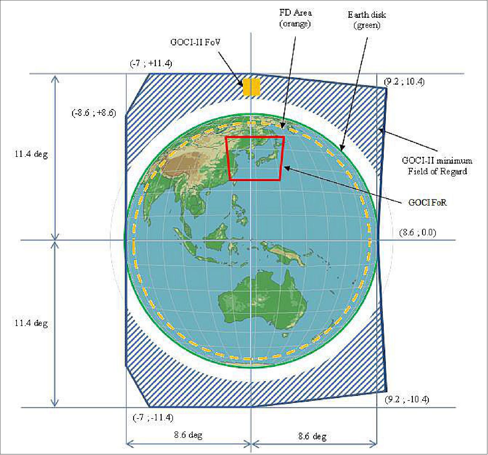
FOR (Field of Regard):
• SN (South North) FOR (±11.4 º)
- 1.1º instrument FOV set as margin
- 1.1º useful FOV for moon and star
- 0.5º margin for pointing bias
• EW (East West) FOR (±8.6º)
- 8.06º FD area
- 0.5ºmargin for pointing bias.
Band | Band Center (nm) | Bandwidth (nm) | Nominal Radiance | Maximum Ocean Radiance | Saturation (Threshold) Radiance | Maximum Cloud Radiance | SNR @ Nominal Radiance |
B1 | 380 | 20 | 93 | 139.5 | 143.1 | 634.4 | 998 |
B2 | 412 | 20 | 100 | 150 | 152 | 601.6 | 1050 |
B3 | 443 | 20 | 92.5 | 145.8 | 148 | 679.1 | 1145 |
B4 | 490 | 20 | 72.2 | 115.5 | 116 | 682..1 | 1228 |
B5 | 510 | 20 | 55.3 | 85.2 | 122 | 665.3 | 1124 |
B6 | 555 | 20 | 55.3 | 85.2 | 87 | 649.7 | 1124 |
B7 | 620 | 20 | 40.3 | 67.8 | 70.5 | 616.5 | 1080 |
B8 | 660 | 20 | 32 | 58.3 | 61 | 589 | 1060 |
B9 | 680 | 10 | 27.1 | 46.2 | 47 | 549.3 | 914 |
B10 | 709 | 10 | 27.7 | 50.6 | 51.5 | 450 | 914 |
B11 | 745 | 20 | 17.7 | 33 | 33 | 429.8 | 903 |
B12 | 865 | 40 | 12 | 23.4 | 24 | 343.8 | 788 |
B13 | 643.5 (PAN) | 483 | - | - | - | - | - |
Band | Band Center (nm) | Primary Usage |
B1 | 380 | CDOM (Chromophoric Dissolved Organic Matter), absorbing aerosol correction |
B2 | 412 | CDOM, chlorophyll |
B3 | 443 | Chlorophyll absorption maximum |
B4 | 490 | Chlorophyll and other pigments |
B5 | 510 | Chlorophyll, absorbing aerosol in oceanic waters |
B6 | 555 | Turbidity, suspended sediment |
B7 | 620 | Phytoplankton species detection |
B8 | 660 | Baseline of fluorescence signal, Chlorophyll, suspended sediment |
B9 | 680 | Fluorescence signal |
B10 | 709 | Fluorescence base signal, atmospheric correction, suspended sediment |
B11 | 745 | Atmospheric correction, vegetation index |
B12 | 865 | Atmospheric correction, aerosol optical depth |
B13 | Wideband | Star Imaging for the INR (Image Navigation and Registration) performance |
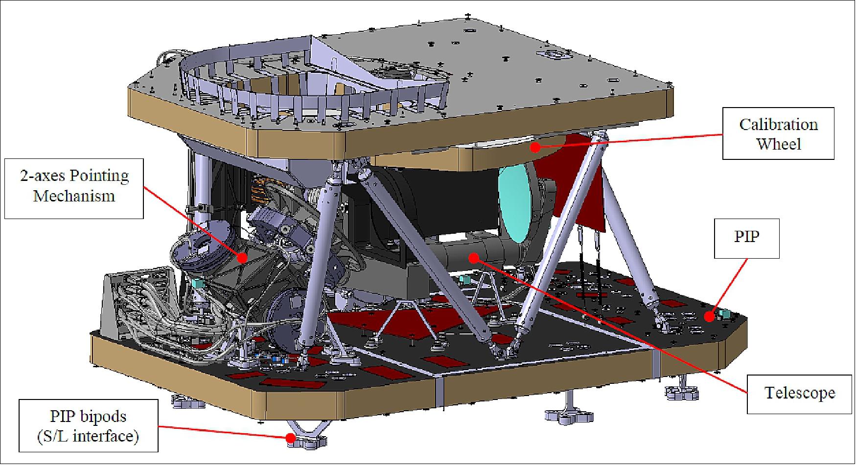
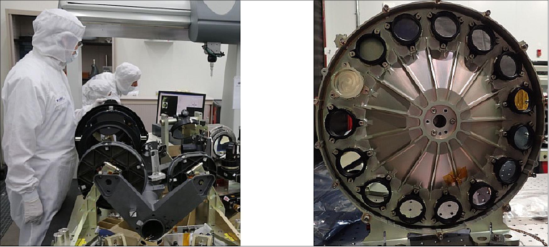
Design overview: The GOCI-II instrument consists of a SU (Sensor Unit) and one IEU (Instrument Electronic Unit) deported inside the satellite platform. The total mass is about 150 kg. The baseline instrument concept is a compact TMA telescope with a 200 mm pupil diameter, featuring a 7.3 Mpixel CMOS array. The 12 narrow band spectral channels are obtained by means of a filter wheel. A 13th wideband spectral channel is implemented for star imaging.
A PIP (Payload Interface Plate) supports a highly stable full SiC (Silicon Carbide) telescope, the two-dimensional FPA (Focal Plane Array) and a FEE (Front End Electronics), the pointing mirror mechanism, the filter wheel mechanism and also the shutter / calibration wheel mechanism.
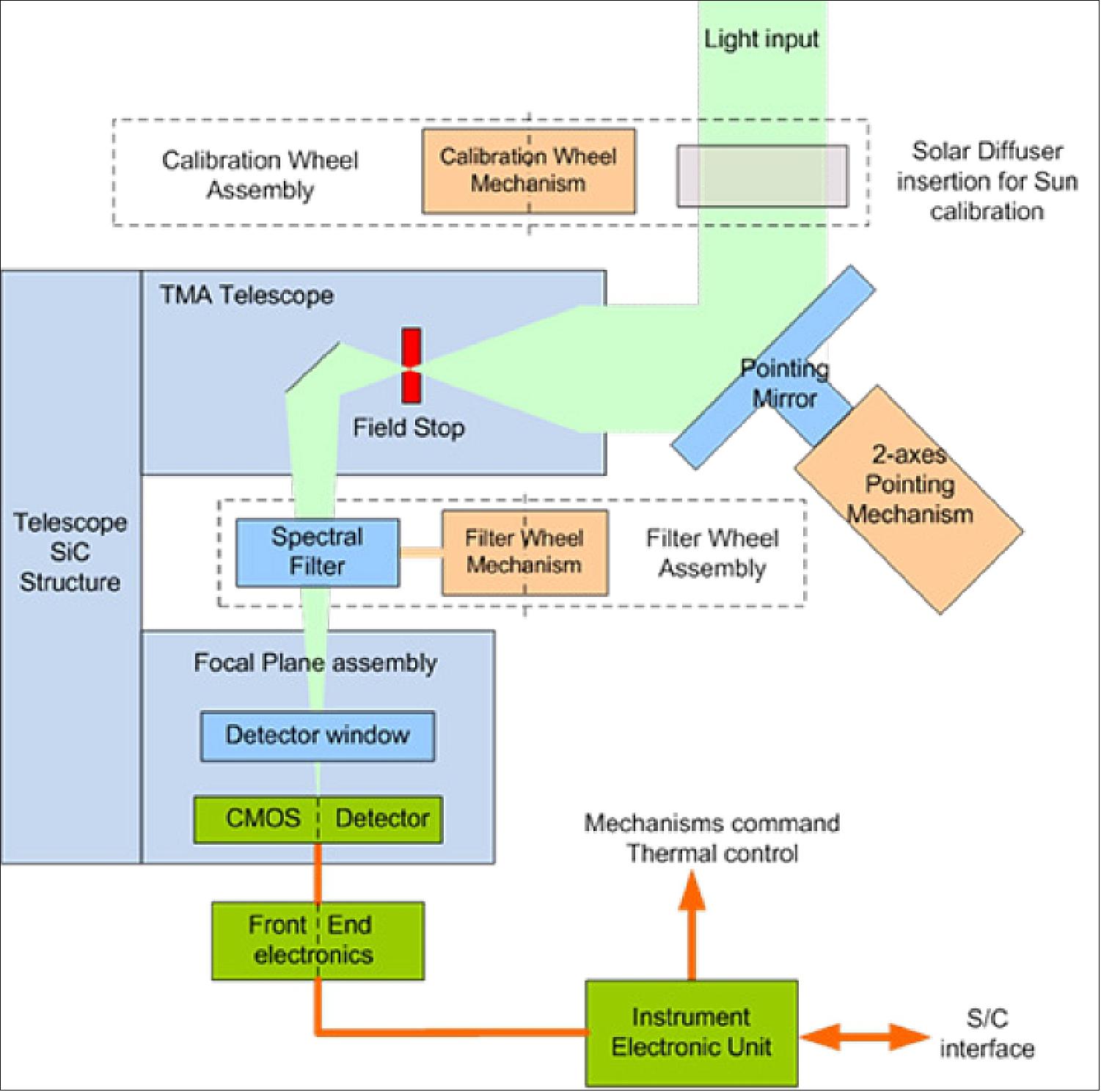
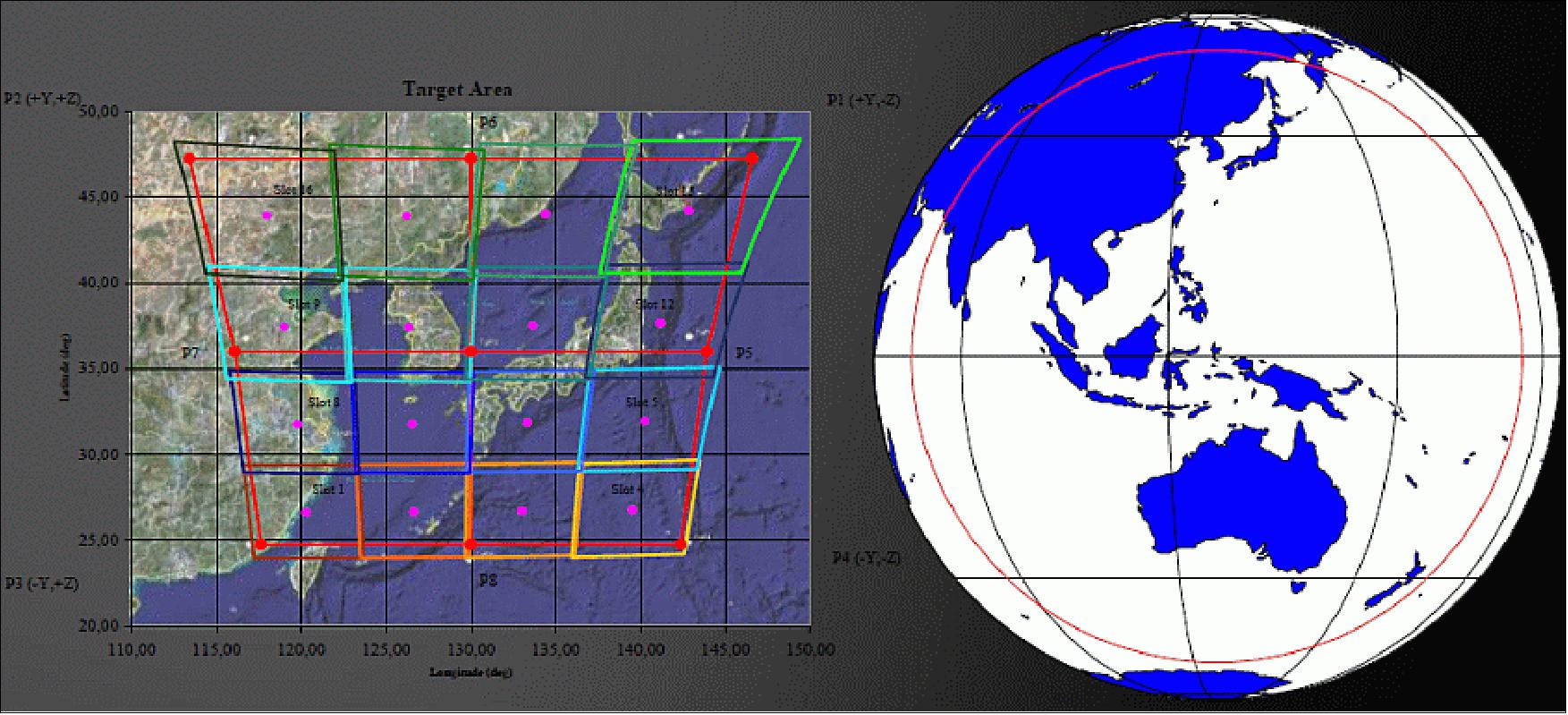
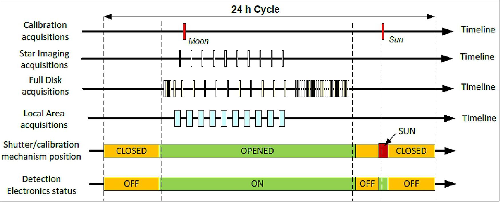
Imaging and Operating Principles: The operating principle consists in imaging a portion of the specified image frame, termed slot. A 2-axes Pointing Mechanism provides a 2D scanning on the Earth. By successive pointing, the array is moved in the field of view to cover the complete image (local area around Korea or full Earth disk in global observation mode). Each slot is imaged over the 12 spectral channels, plus a dark position for offset monitoring and correction. The image is acquired for two gain levels corresponding to sea and cloud radiance levels, respectively. The image data are sent in quasi-real-time to the ground. One single slot acquisition period takes less than 100 seconds in Local Observation mode and less than 60 seconds in Global Observation mode. Star images are done from time to time to calibrate the instrument LOS (Line of Sight) and feed the image ground processing (INR). The instrument in-orbit radiometric calibration is achieved by a combination of Solar Calibration (possible every day) and Moon calibration (monthly).
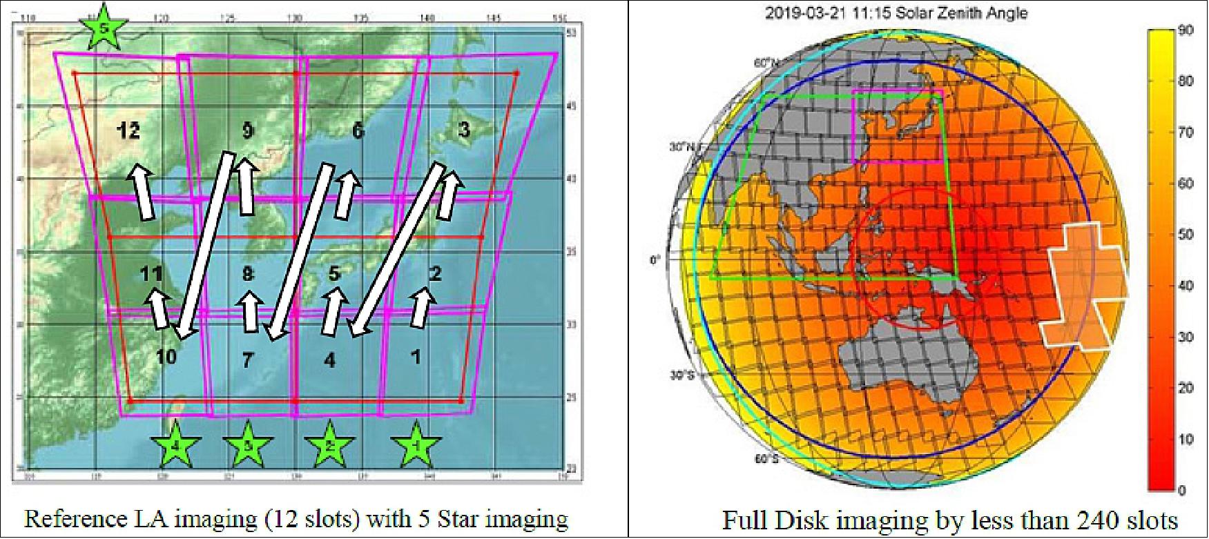
The instrument operations are managed by a programmable timeline uploaded in the instrument electronics. The timeline covers 24h operations (mechanism motions, slot acquisitions, detection electronics on/off) and is automatically repeated by default. Figure 35 illustrates a typical set of operations that can be autonomously executed by the instrument and shows the instrument flexibility for Earth observation and calibration activities. The coverage of the Reference Local Area is done in a short time frame (20 minutes in 12 slots) giving the user up to 10 minutes per hour for complementary acquisitions: star imaging for efficient INR processing and Full Disk slots to fulfill the global coverage mission during daytime with optimal illumination conditions.
Main challenges of GOCI-II development: Although the overall instrument architecture and operation principles are inherited from the first GOCI, the specified performance enhancements required major new developments of key components:
• New dedicated CMOS image sensor to fit the smaller sampling distance with increased number of pixels while keeping high level radiometric and MTF performances. This detector was developed in partnership between Airbus DS and ISAE.
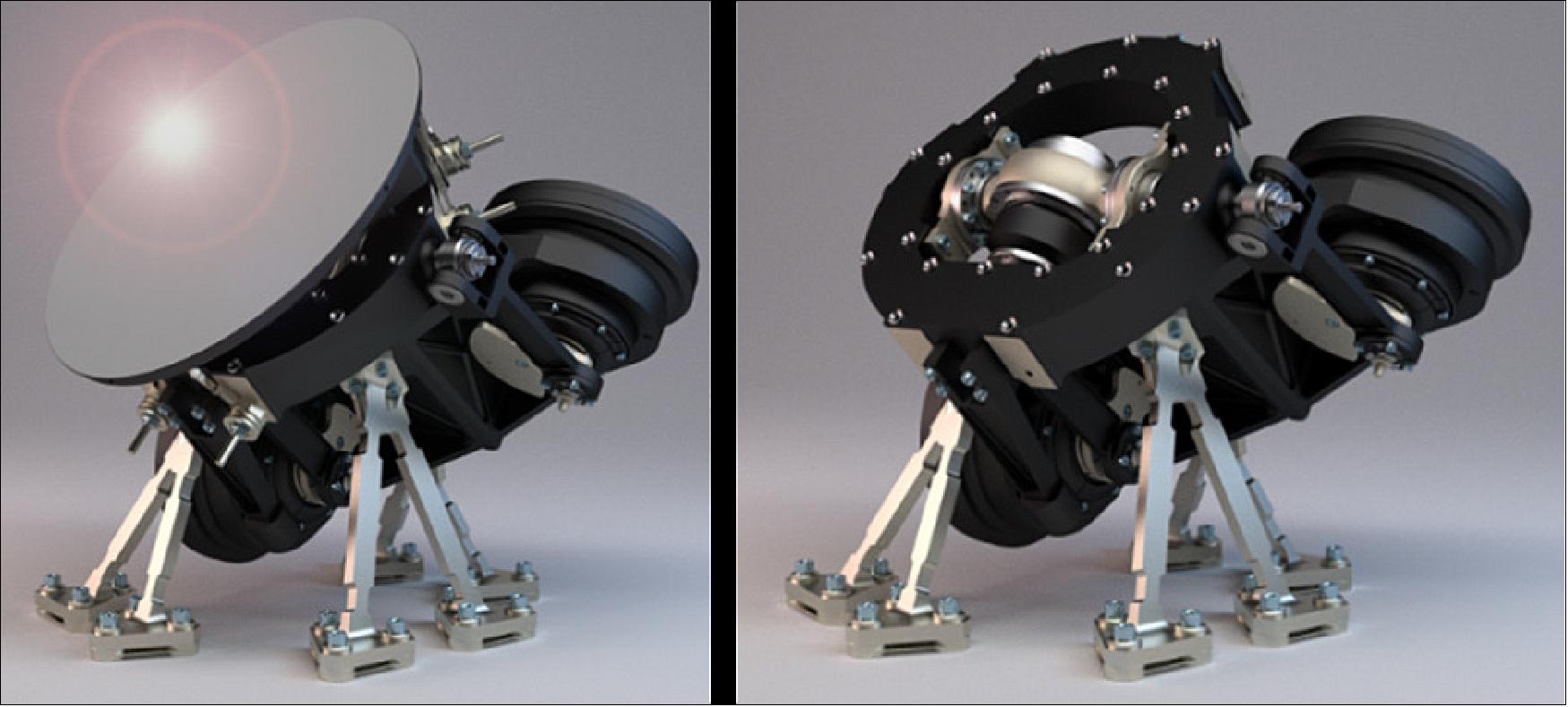
• New 2-axes POM (Pointing Mechanism, Figure 36) to manage the enlarged instrument FOR (Field of Regard) and the increased pointing mirror size and mass, while keeping a high stability, an accurate restitution of the pointing direction and the capability of being launched without a Launch Locking Device. The POM was designed and developed by Airbus DS in Toulouse. A fully representative qualification model has been build and the qualification tests will be completed before the end of the summer 2016.
• The IEU (Instrument Electronic Unit) that has to manage more detection chains and has to provide higher level of autonomy and flexibility for the user, while keeping low size and mass (7.5 kg). The IEU was developed by the Airbus DS electronics division. The full functional and performance validation was reached in 2015 on an EM model and the Flight Model has been delivered in mid-2016.
• The dedicated TMA telescope with enlarged pupil and improved straylight performances (field stop implementation) while keeping compactness and diffraction limited performances. The SiC telescope structure and mirrors are designed by Airbus DS and manufactured by Mersen Boostec. Mirror polishing is done by Amos (Belgium) and coating by Schott (Switzerland).
• The optical filters were newly designed by OBJ (Optics Blazers Jena) in Germany with barrels made by Sodern. After full qualification on dedicated models, the Flight Models have been delivered in mid-2016.
• Two Sun diffusers made of HOD material are also implemented to enhance radiometric calibration.
• In addition, several key elements (harness, structures, EGSE) have been subcontracted to the Korean industry.
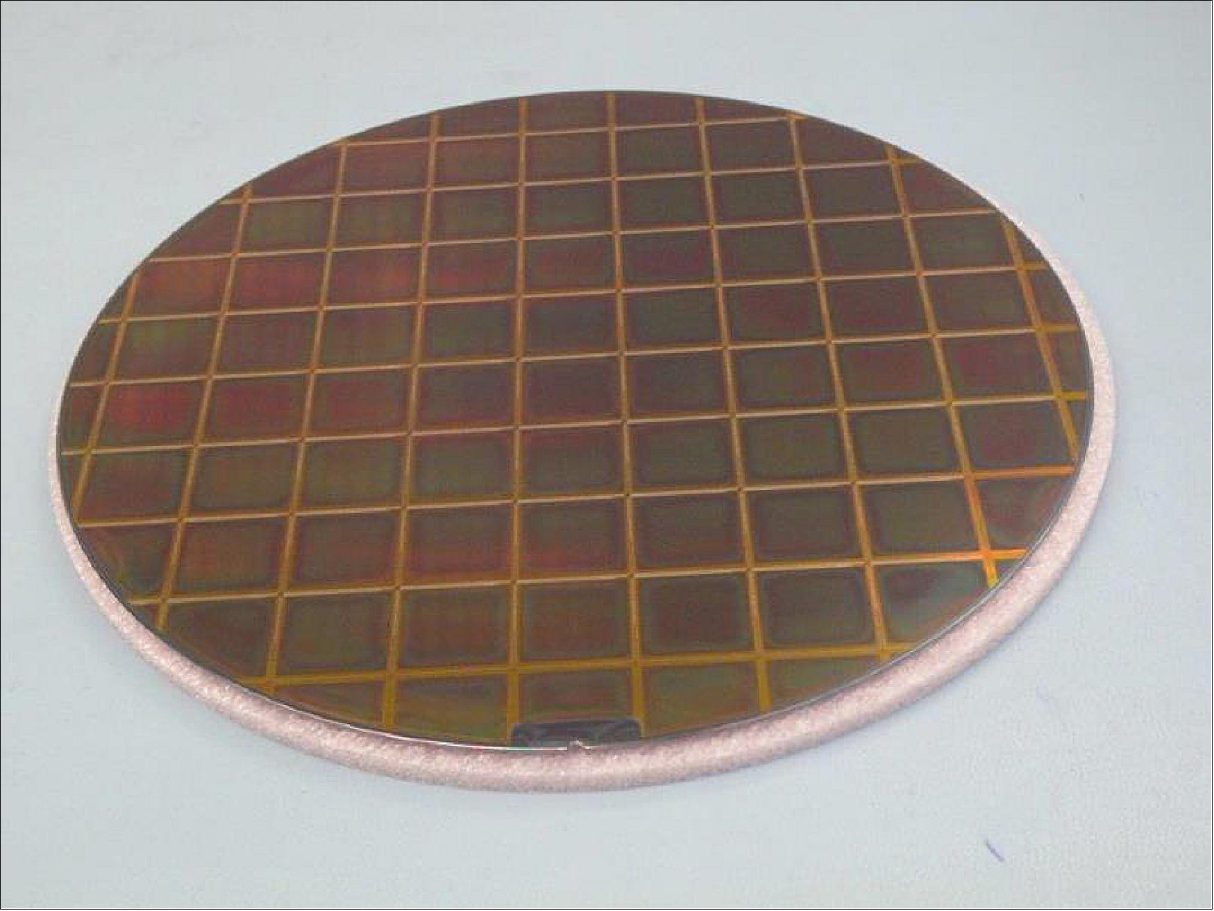
The GOCI-II CMOS imaging sensor: In order to meet the demanding radiometric performance requirements, a 7.3Mpixel CMOS imaging sensor has been specifically designed for the GOCI-II instrument. Die design and architecture have been carried out in partnership with ISAE (Institut Supérieur de l’Aéronautique et de l’Espace), Toulouse, France. Following the design phase, the silicon wafers (Figure 38) have been manufactured and processed in an Asian semiconductor foundry.
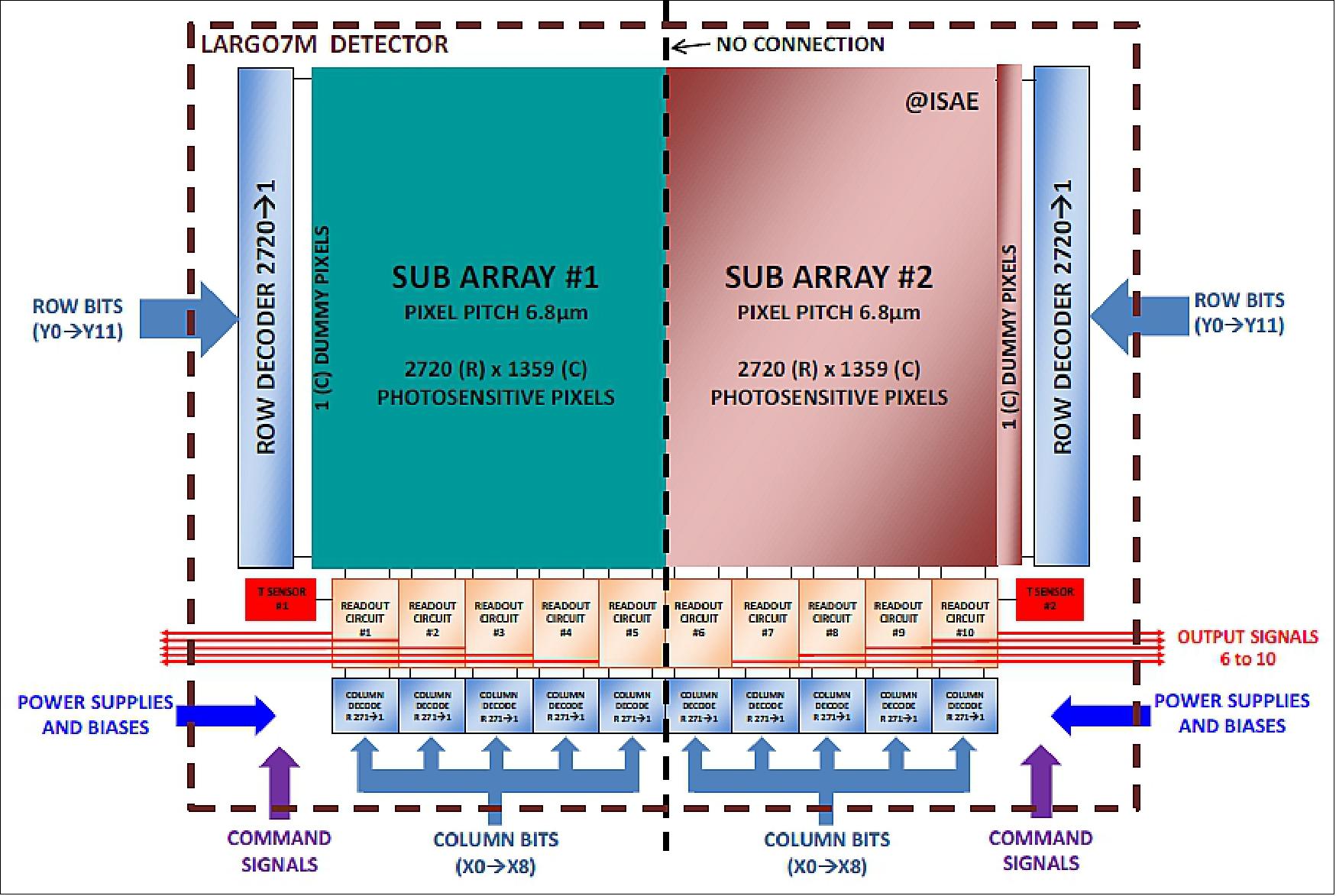
The 7.3MPixels CMOS image sensor features:
• 2720 rows by 2718 columns of 6.8μm pitch pixels with 10 analog outputs to answer at the closest to spatial resolution and acquisition duration requirements (Figure 39)
• Pixel topology optimisation to meet detection efficiency and Modulation Transfer Function challenging requirements
• Adjustment of in pixel conversion factor (CVF) including design and manufacturing tolerances for SNR (Signal-to-Noise Ratio) and dynamic range budgets.
GOCI-II development schedule: The GOCI-II development started in July 2013 and the instrument Flight Model delivery is scheduled for mid-2017. The design, procurement and integration phase take place in Airbus DS in Toulouse (France) with the help of a detached Joint Development Team from KARI and KIOST.
A GOCI-II EM instrument made of EM electronics, including fully representative detector and mechanisms was built for early verification of the detection chains and full instrument functional validation. The EM instrument was delivered to KARI beginning of 2016.
The completion of the GOCI-II Flight Model integration is scheduled by the end of 2016. The first set of performance acceptance tests will be done at the Airbus DS premises in ambient conditions. Then the instrument will be shipped to Korea beginning of 2017 and all the environmental tests (mechanical, thermal vacuum, EMC) will be performed within the KARI facilities in close collaboration between the French and Korean teams.
After the completion of the acceptance tests, the instrument will be formally delivered to KARI. It will then be mounted on GK-2B satellite and launched aboard an Ariane-5 vehicle in 2019.
Ground System
GK2A/2B Ground Centers
The GK2A/2B will have ground systems designed to support missions and operations over 10 years, respectively. It is composed of the SOC (Satellite Operations Center), NMSC (National Meteorological Satellite Center), KOSC (Korea Ocean Satellite Center), and ESC (Environmental Satellite Center), as shown in Figure 40. The SOC provides the functionality to operate the GK2A/2B satellite by receiving and transmitting commands to satellites. The NMSC, KOSC, and ESC converts payload data from the satellite into calibrated data. The AMI and GOCI-I/GOCI-II image data are disseminates to end users via the GK2A. The SOC and NMSC/KOSC/ESC will exchange the satellite operations data or image data using the terrestrial data. When required from NMSC, the SOC can resume backup xRIT(LRIT/HRIT/UHRIT) broadcasting service. The each ground center will be integrated by their organisations’ responsibility before the satellite launch. 52)
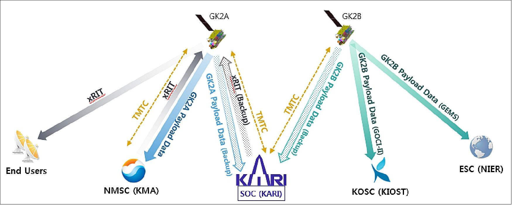
SOC Ground System Configuration: The SOC will be located in Daejeon and fully operated by KARI. It serves the satellite operations and backup data preprocessing with two 9 meter diameter antennas for GK2A and GK2B respectively. The GK2A and 2B use S-band, X-band, and L-band communication frequencies. X-band is used for the downlink of payload data and the downlink of UHRIT dissemination channel.
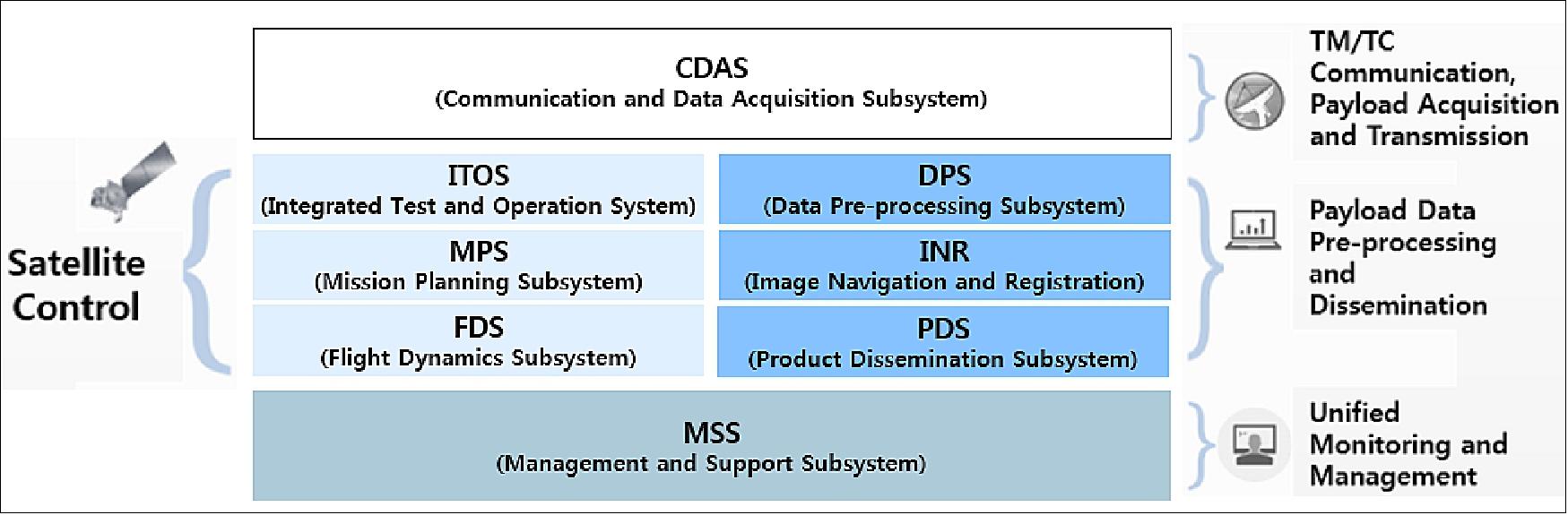
The SOC is composed of following subsystems as shown in Figure 41.
- CDAS (Communication and Data Acquisition Subsystem) for TTC and imagery data
- ITOS (Integrated Test and Operation System) for TM/TC processing
- MPS (Mission Planning Subsystem) for Mission Scheduling; Two MPSs for GK2A and GK2B satellite
- FDS (Flight Dynamics Subsystem) for Maneuver Planning
- DPS (Data Pre-processing Subsystem) for Radiometric Calibration; Three dedicated DPSs for AMI, GOCI-II, and GEMS
- INR (Image Navigation and Registration) for Geometric Calibration; Three dedicated INRs for AMI, GOCI-II, and GEMS
- PDS (Product Dissemination Subsystem) for AMI xRIT Broadcasting; One PDS for AMI payload
- MSS (Management and Support Subsystem) for Unified Monitoring and Management to SOC operators.
SOC Ground System Development Plan: Most ground subsystems of SOC are required to process both GK2A and 2B satellite data during the mission life time. Therefore possible subsystems are being development to cover both satellites as possible, though GK2A and GK2B satellite launch schedules are different. Some subsystems are dedicated for each payload data and payload development schedule. Unified subsystems for GK2A and 2B can be operated as separated systems, menu/function for each GK2A and 2B by configurations.
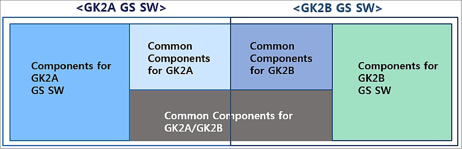
The SOC ground SW development is in progress with command components in order to improve development efficiency and consistent results among subsystems. Functionalities and interfaces which are required repetitively to all ground SW are developed as “common components” to be reused to all ground SW development. Common components can be categorised for entire GK2A/2B GS and for GK2A GS only, GK2B GS only as follows. There common components will be implemented in Java language for SW reusability.
• Common Components for GK2A/GK2B GS
- Handling components of Log, Status, Audio/Video alarm
- Access components of Data I/O, DBMS, User Authentication
- Common Interface components (FTP, Socket, RPC, REST API etc.)
- Common UI components (Graphic control, User Login, Search control etc.)
• Common Components for GK2A GS
- Access components for GK2A S/C, AMI Configuration and Telemetry
- AMI image products components
- Interface data components for GK2A GS SW
• Common Components for GK2B GS
- Access components for GK2B S/C, GOCI-II, GEMS Configuration and Telemetry
- GOCI-II, GEMS image products components
- Interface data components for GK2B GS SW
Major Differences between COMS and GK2 Ground System
Comparing to the existing COMS system, the GK2A/2B ground system is required in the functional and performance aspects as follows:
- Satellite collocation operation for COMS and GK2A/2B
- Manual/automatic optional operation in mission scheduling and flight dynamics
- GEMS (Hyperspectral payload) preprocessing added
- Increased payload data volume more than 20 times in case of AMI
- Faster AMI timeliness requirement compared to the current COMS’ requirement from 15minutes to 3 minutes (Calibration and broadcasting shall be completed within 3 minutes after the full Earth observation)
- New ultra-HRIT broadcasting service to disseminate the all AMI L1B product in the DVB-S2 protocol
- Compatible LRIT/HRIT services with the current COMS’ services.
In addition to things mentioned above, there are more different items. The Ka-band communication payload (communication missions) does not exist in the GK2A/2B satellites but the GEMS (environmental monitoring missions) will be embarked to GK2B.
The AMI will exhibit higher performance in temporal, spatial, and spectral resolution in comparison with the COMS MI (Metrological Imager). The GK-2A AMI will provide 16 spectral bands in the visible, near-IR, and IR spectrum, 5 times better than current COMS MI. Its spatial resolution will be improved 2 times better capability of COMS. Moreover, the AMI can observe the full disk image as short as 10 minutes, 3 times faster than current imager. Large amount of AMI raw data will be delivered to ground in X-band.
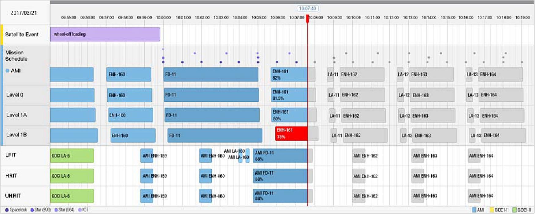
For SOC which performs satellite operations and data preprocessing, entire SOC ground system and satellites operational status will be displayed in comprehensive configurations as shown in Figure43. Based on the COMS ground system experience, operator friendly functions such as report generation and primary/backup synchronisation functions will be added to GK2A/2B ground system.
GK2 Broadcasting Service
The GK2A satellite will be equipped with an on-board transponder for data direct broadcasting like the COMS. The AMI/GOCI-II imagery data, AMI level 2 product and value-added data will be disseminated to end users. The GK2 broadcasting service can be categorised into 3 service channels depending on data rate and contents: LRIT, HRIT and UHRIT.
The GK2 LRIT (Low Rate Information Transmission) and HRIT (High Rate Information Transmission) will take over the current COMS’ LRIT and HRIT broadcasting service. The GK2 ground system will process down-sizing of AMI imagery data in close bands with current MI to generate approximately identical contents and formats. Not to make any technical problems to existing COMS end-users systems, the GK2 LRIT and HRIT will be downlinked to end users system through same RF characteristics and data format. The current COMS provides LRIT and HRIT broadcasting service in L-band from 2011 for free but user registration is required to key information from KMA (Korean Meteorological Administration).
The UHRIT (Ultra-UHRIT) will be newly added as a means of AMI imagery data dissemination in full resolutions and channels using DVB-S2 (Digital Video Broadcasting-Satellite-Second Generation). The current COMS end-user can receive GK2 LRIT/HRIT signals but users who want to receive new UHRIT channel are required X-band reception system and processing system including DVB-S2 equipment. Table 12 shows the GK2 LRIT, HRIT and UHRIT downlink characteristics. Detailed sequences of AMI observation/dissemination mode and time frames are under consideration by KMA.
Parameter | LRIT | HRIT | UHRIT |
Downlink frequency | 1692.14 MHz | 1695.4 MHz | 8307.5 MHz |
Max. data rate | 256 kbit/s | 3 Mbit/s | 31 Mbit/s |
Coding | RS(255, 223,4) + Conv(1/2, K=7) | RS(255, 223,4) + Conv(1/2, K=7) | BCH + LDPC 2/3 of DVB-S2 standard |
Polarisation | Linear in EW | Linear in EW | LHCP |
Modulation | NRZ-L/BPSK | NRZ-L/QPSK | NRZ-L/8PSK |
Compression | Yes | Yes | Yes |
Encryption | Yes | Yes | Yes |
The SOC ground system for GK2 is required to be operated 24hr/365days and to control 2 satellites, and high-resolution/ large amount of data preprocessing during lifetime. The required data preprocessing time has been shorten though image resolution and data amount have been increased. Therefore proper distributed processing, automatic recovery mechanism, optimised file transfer methods are being selected by related prototyping tests.
The SOC ground system for GK2A will be integrated in 2017 and SOC for GK2B will be integrated in 2018. During the GK2A IOT phase, GK2B SOC systems are supposed to be integrated and tested. The overlapped period in the SOC ground system development schedule for GK2A and 2B can get solved by using efficient development policy such as common component modules and unified operations system development. The unified operations system and automatic processing in mission planning/flight dynamics are expected to reduce burden for 2 satellite operations.
References
1) Kum-Lan Kim, “Current and Future Plan of KMA Satellite Program,” 4th Asia-Oceania Meteorological Satellite Users Conference, Melbourne, Australia, October, 9-11, 2013, URL: http://www.virtuallab.bom.gov.au/files/9313/8119/0983/4th_AOMSUC_Abstracts_-_FINAL.pdf
2) Dohyeong Kim, “Satellite Program of KMA,” 7th ET-SAT (Expert Team on Satellite Systems) meeting, April 17-20, 2012, Geneva, Switzerland,URL: http://www.wmo.int/pages/
prog/sat/meetings/documents/ET-SAT-7_Doc_05-07_KMA-update.pdf
3) “GEO-KOMPSAT-2 Program,” KARI, URL: http://eng.kari.re.kr/sub01_01_02_09
4) Koon-Ho Yang, ”Advanced Meteorological Imager (AMI) Development for GEO-KOMPSAT-2A,” The 1st KMA International Meteorological Satellite Conference, Seoul, Korea, November 16-18, 2015, URL: http://www.kmaimsc.kr/html/menu1_sub4.php
5) ”Geostationary Earth Orbit (GEO) Satellite,” KARI, URL: http://www.kari.re.kr/eng/sub03_02_02.do
6) Sang-Ryool Lee, ”How GK2(GEO-KOMPSAT -2) Program is Ensuring COMS Follow-on Mission in Korea,” 6th Annual MilSatCom Asia-Pacific, Singapore, May 26-27, 2016
7) “Northrop Grumman to Supply Navigation System SKorea's KOMPSAT-2 Birds,” Space Daily, June 11, 2014, URL: http://www.spacedaily.com/reports/Northrop_Grumman_to_Supply
_Navigation_System_for_South_Koreas_GEO_KOMPSAT_2_Satellites_999.html
8) “Airbus Defence and Space supports South Korean weather satellite programme,” Airbus Defence and Space, Sept. 9, 2014, URL: http://airbusdefenceandspace.com/
airbus-defence-and-space-supports-south-korean-weather-satellite-programme/
9) ”JCSAT-17 and GEO-KOMPSAT-2B are prepared for their Ariane 5 launch to geostationary transfer orbit,” Arianespace, 27 January 2020, URL: https://www.arianespace.com
/mission-update/va252-payload-preparations/
10) ”The Two Passengers for Arianespace Flight VA246 Safely Ensconced in French Guiana for Launch,” Satnews Daily, 03 November 2018, URL: http://www.satnews.com/story.php?number=524100538
11) ”Airbus delivered GOCI-II instrument to the Korean space agency,” Airbus DS, 20 Dec. 2017, URL: http://www.airbus.com/newsroom/press-releases/en/2017/12/delivered-goci-II.html
12) ”Harris Corporation Delivers Advanced Weather Satellite Instrument to South Korea,” Harris Press Release, June 21, 2017, URL: https://www.harris.com/press-releases/2017/
06/harris-corporation-delivers-advanced-weather-satellite-instrument-to-south
13) ”Thales Alenia Space completes delivery of panels for the communications payloads on South Korea’s GEO-KOMPSAT-2 satellites,” Thales Alenia Space, April 18, 2017, URL: https://www.thalesgroup.com/en/worldwide/space/press-release/
thales-alenia-space-completes-delivery-panels-communications-payloads
14) ”Ariane 5’s sixth launch this year,” ESA, 04 December 2018, URL: http://m.esa.int/Our_Activities/Space_Transportation/Ariane_5_s_sixth_launch_this_year2
15) Stephen Clark, ”Ariane 5 • GSAT 11 & GEO-Kompsat 2A,” Spaceflight Now, 25 October 2018, URL: https://spaceflightnow.com/launch-schedule/
16) ”Geo-KOMPSAT-2A will be launched in Nov 2018,” KMA (Korea Meteorological Administration), 1 August 2018, URL: http://www.kma.go.kr/eng/aboutkma/notice.jsp?
bid=eng_notice&mode=view&num=103&page=1&field=&text
17) ”Arianespace to launch GEO-KOMPSAT 2A and 2B satellites for Korea Aerospace Research Institute,” Arianespace, Feb. 13, 2015, URL: http://www.arianespace.com/press-release/
arianespace-to-launch-geo-kompsat-2a-and-2b-satellites-for-korea-aerospace-research-institute/
18) Peter B. de Selding, ”Arianespace Beats SpaceX To Launch Two South Korean Weather Satellites,” Space News, February 13, 2015, URL: http://spacenews.com
/arianespace-beats-spacex-to-launch-two-south-korean-weather-satellites/
19) ”Arianespace orbits two satellites – JCSAT-17 and GEO-KOMPSAT-2B – to support connectivity and environmental monitoring in Asia,” Arianespace Press Release, 18 February 2020, URL: https://www.arianespace.com/press-release/ariane-5-success-va252/
20) Joe Atkinson, ”First Satellite in Global Air Quality Constellation Launches,” NASA, 20 February 2020, URL: https://www.nasa.gov/feature/langley/first-satellite-in-global-air-quality-constellation-launches
21) “'The Eyes of Space': Cheollian 2B satellite to begin providing marine satellite images,” KARI News Release, 8 October 2020, URL: https://www.kari.re.kr/cop/bbs/BBSMSTR_000000000031/selectBoardArticle.do?
nttId=7736&kind=&mno=sitemap_02&pageIndex=1&searchCnd=&searchWrd=
22) ”First Release of the Ocean Color Images of the Seas around the Korean Peninsula taken by Cheollian 2B,” KARI News Release, 25 May 2020, URL: https://www.kari.re.kr/cop/bbs/BBSMSTR_000000000031/selectBoardArticle.do?
nttId=7631&kind=&mno=sitemap_02&pageIndex=1&searchCnd=&searchWrd=
23) ”Ball Aerospace-built Geostationary Air Quality Instrument Launches Successfully,” Space Daily, 19 February 2020, URL: https://www.spacedaily.com/reports/
Ball_Aerospace_built_Geostationary_Air_Quality_Instrument_Launches_Successfully_999.html
24) ”GK2A / Introduction,” NMSC of KMA, URL: https://nmsc.kma.go.kr/enhome/html/base/cmm/selectPage.do?page=satellite.gk2a.intro
25) ”GEO-KOMPSAT-2A transition to operation,” KMA, 25 July 2019, URL: http://ane4bf-datap1.s3-eu-west-1.amazonaws.com/wmocms/s3fs-public/ckeditor/files/
20190725_Geo-KOMPSAT-2A_opeartion_.pdf?8HAd.7EPYfHuXQt3xFwDyDLYW0ZrITGx
26) Information provided by Sungdong Park, Chairman, Satrec Initiative Co., Ltd., Daejeon, Korea.
27) Daeyun Shin, “Current status and future plan for Space Weather in KMA,” 2012, URL: http://www2.nict.go.jp/aeri/swe/aoswa/wsreport2012/pdf/%5BO-09%5Dpresentation.pdf
28) Joo-Hyung Ryu, “GEO New Mission and Synergy,” International Ocean Color Science (IOCS) Meeting, Darmstadt, Germany, May 6-8, 2013, URL: http://iocs.ioccg.org/
wp-content/uploads/1450-joo-hyung-ryu-iocs-2013-05_IOCS.pdf
29) “Satellite Program of KMA,” KMA/NMSC (Korea Meteorological Administration/National Meteorological Satellite Center), 7 th ET-SAT meeting, April 17-20, 2007, Geneva, Switzerland, URL: https://web.archive.org/web/20191115004000/http://www.wmo.int/pages/prog/sat/meetings/documents/ET-SAT-7_Doc_05-07_KMA-update.pdf
30) Sang-Jin Lyu, ”Current Status and Future Plan of KMA Satellite Program,” NOAA Satellite Conference, Greenbelt, MD, USA, April 27-May 1, 2015, URL: http://satelliteconferences.noaa.gov
/2015/doc/presentation/1.9_NSC2015_Session_1.9_Lyu.pdf
31) “ITT Exelis advanced weather imager technology to improve forecasting capabilities in South Korea,” Exelis, April 8, 2013, URL: [web source no longer available]
32) “Introduction of DAta PROcessing System (DAPROS) for the Geo-KOMPSAT-2A of KMA,” WMO RA II WIGOS Project Newsletter, Vol. 4 No. 4, December 2013, URL: https://www.jma.go.jp/jma/jma-eng/satellite/ra2wigosproject/documents/RA-2-WIGOSPP_Newsletter-Vol4-N4.pdf
33) ”Korea Aerospace Research Institute complete review of new satellite imager that will improve weather forecasting,” Exelis, May 27, 2015, URL: http://www.exelisinc.com/news/pressreleases/Pages/
Exelis,-Korea-Aerospace-Research-Institute-complete-review-of-new-satellite-imager-that-will-improve-weather-forecasting.aspx
34) “KMA launch contract for GK2A space weather mission,” RA II (WMO Regional Association-II) WIGOS Project Newsletter, WMO, Vol. 5 No. 1, March 2014, URL: https://www.jma.go.jp/jma/jma-eng/satellite/ra2wigosproject/documents/RA-2-WIGOSPP_Newsletter-Vol5-N1.pdf
35) Jae-Gwang Won, Hye-Sook Lee, Jong-Ho Seon, Jae-Jin Lee, ”Overview on KMA KSEM: The first Korean Space Weather mission flying on Geostationary orbit,” he 1st KMA International Meteorological Satellite Conference, Seoul, Korea, November 16-18, 2015, URL: http://www.kmaimsc.kr/html/menu1_sub4.php
36) U. Auster, W. Magnes, M. Delva, A. Valavanoglou, S. Leitner, O. Hillenmaier, C. Strauch, P. Brown, B. Whiteside, M. Bendyk, A. Hilgers, S. Kraft, J. P. Luntama, J. Seon, ”Space weather magnetometer set with automated AC spacecraft field correction for GEO-KOMPSAT-2A,” Proceedings of the 2016 ESA Workshop on Aerospace EMC(Electromagnetic Compatibility), Valencia, Spain, May 23-25, 2016, (ESA SP-738, May 2016)
37) T. L. Zhang, S. Pope, M. Balikhin, C. T. Russell, L. K. Jian, M. Volwerk, M. Delva, W. Baumjohann, C. Wang, J. B. Cao, M. Gedalin, K.-H. Glassmeier, K. Kudela, ”Venus Express observations of an atypically distant bow shock during the passage of an interplanetary coronal mass ejection,” Journal of Geophysical Research, Vol. 113, E00B12, doi:10.1029/2008JE003128, 2008, URL: http://onlinelibrary.wiley.com/store/10.1029/2008JE003128/asset/
jgre2523.pdf?v=1&t=ipi5eje4&s=9fd9b01118a633411fb2038cd66668ff003026f0
38) Stefan Leitner, Aris Valavanoglou ; Patrick Brown ; Christian Hagen Werner Magnes, Barry J. Whiteside, Christopher M. Carr, Magda Delva, Wolfgang Baumjohann, ”Design of the Magnetoresistive Magnetometer for ESA’s SOSMAG Project,” IEEE Transactions on Magnetics, Volume:51 , Issue: 1, ISSN : 0018-9464, Feb. 2, 2015, DOI: 10.1109/TMAG.2014.2358270
39) “KMA Report on the Status of the Current and Future Satellite,” The 41st meeting of the Coordination Group for Meteorological Satellites (CGMS-41), Tsukuba, Japan, July 8-12, 2013, CGMS-41 KMA-WP-01, URL: http://www.cgms-info.org/documents-cgms/2067827.pdf
40) Jhoon Kim, Mijin Kim, Ukkyo Jeong, Myungje Choi, Sujeong Go, and the GEMS Science Team, ”GK-2B Atmospheric Environment Mission, GEMS : Atmospheric Composition Monitoring in High Temporal and Spatial Resolution,” The 1st KMA International Meteorological Satellite Conference, Seoul, Korea, November 16-18, 2015, URL: http://www.kmaimsc.kr/html/menu1_sub4.php
41) “Ball Aerospace Wins Contract to Build Air Quality Sensor for KARI - Atmospheric pollution sensor first Ball contract with South Korea,” Space Daily, May 13, 2013, URL: http://www.spacedaily.com/reports/
prnewswire-space-news.html?doc=201305131026PR_NEWS_USPR_____LA12269&
showRelease=1&dir=0&categories=AEROSPACE-AND-SPACE-EXPLORATION&
andorquestion=OR&&passDir=0,1,2,3,4,5,6,15,17,34
42) “Ball Aerospace Moving Ahead on TEMPO and GEMS Air Quality Sensors,” Space Daily, April 29, 2014, URL: http://www.spacedaily.com/reports/
Ball_Aerospace_Moving_Ahead_on_TEMPO_and_GEMS_Air_Quality_Sensors_999.html
43) Jhoon Kim, “Planned GEO Mission in Korea for Air Quality Measurements : GEMS(Geostationary Environmental Monitoring Spectrometer),” NASA-MEST (Ministry of Education Science and Technology of Korea) Technical Group for Geostationary Atmospheric Composition Measurements Meeting, Washington D.C., August 13, 2009, URL: http://geo-cape.larc.nasa.gov/docs/AUG2009MEST/2009-GEMS-jkim.pdf
44) M. E. Park, C. H. Song, R. S. Park, J. Lee, J. Kim, S. Lee, J.-H. Woo, G. R. Carmichael, T. F. Eck, B. N. Holben, S.-S. Lee, C. K. Song, Y. D. Hong, “New approach to monitor transboundary particulate pollution over Northeast Asia,” Atmospheric Chemistry and Physics, Vol. 14, 2014, pp. 659-674, doi:10.5194/acp-14-659-2014
45) Jhoon Kim, GEMS Team, ”Overview and Status of GEMS,” 2014, URL: http://tempo.si.edu/presentations/May2014/Kim.pdf
46) Roz Brown, “Ball Aerospace Moving Ahead on TEMPO & GEMS Air Quality Sensors,” BATC News Release, April 22, 2014, URL: http://www.ballaerospace.com/page.jsp?page=30&id=583
47) ”Ball Aerospace GEMS Instrument Passes Critical Design Review ,” PRNewswire, April 1, 2015, URL: http://www.prnewswire.com/news-releases/
ball-aerospace-gems-instrument-passes-critical-design-review-300059091.html
48) Steve Schuster, “Astrium signs contract with Korean Aerospace Research Institute,” Satellite Today, July 24, 2013, URL: http://www.satellitetoday.com/publications/st/stbriefs/
2013/07/24/astrium-signs-contract-with-korean-aerospace-research-institute/
49) Pierre Coste, Franck Larnaudie, Philippe Luquet, Haengpal Heo, Junpyung Jung, Gmsil Kang, Sangyoun Shin, Sangsoon Yong, Young-Je Park, ”Development of the new generation of Geostationary Ocean Color Imager,” Proceedings of the ICSO 2016 (International Conference on Space Optics), Biarritz, France, 18-21 October, 2016, URL: http://esaconferencebureau.com/custom/icso/2016/index.htm
50) Joo-Hyung Ryu, “GEO New Mission and Synergy,” International Ocean Color Science Meeting 2013, Darmstadt, Germany, May 6-8, 2013, URL: http://iocs.ioccg.org
/wp-content/uploads/1450-joo-hyung-ryu-iocs-2013-05_IOCS.pdf
51) Young-Je Park, Seongick Cho, Hee-Jeong Han and other KOSC staff, ”GK-2B Ocean Mission, GOCI-II — Development Status and Application Perspective,” The 1st KMA International Meteorological Satellite Conference, Seoul, Korea, November 16-18, 2015, URL: http://www.kmaimsc.kr/html/menu1_sub4.php
52) Hyun-Su Lim, Jin-Hyung Park, Dong-Gyu Kim, ”The GK2A/2B Ground System after the COMS,” Proceedings of the 14th International Conference on Space Operations (SpaceOps 2016), Daejeon, Korea, May 16-20, 2016, paper: AIAA 2016-2320, URL: http://arc.aiaa.org/doi/pdf/10.2514/6.2016-2320
Spacecraft Launch Mission Status Sensor Complement Ground Segment References Back to top