ExoplanetSat
Non-EO
Cancelled
MIT
Quick facts
Overview
| Mission type | Non-EO |
| Agency | MIT |
| Mission status | Cancelled |
ExoplanetSat
ExoplanetSat is a cooperative nanosatellite technology demonstration mission (a 3U CubeSat) of MIT (Massachusetts Institute of Technology) and Draper Laboratory, both of Cambridge, MA, USA. The overall objective is to test the ability to use nanosatellites to search for unmapped planets - and to complement existing planet-hunters like NASA’s Kepler space telescope (launch March 6, 2009, mass = 1039 kg) and ground-based assets. Other examples in the same observation category are: the CoRoT (Convection, Rotation and planetary Transits) mission of CNES (launch Dec. 27, 2006, mass = 630 kg), and the MOST (Microvariability and Oscillations of Stars) microsatellite of CSA, Canada (launch June 30, 2003, mass of 54 kg).
If the performance of the tiny prototype ExoplanetSat is considered adequate, the demonstration will offer NASA the ability to dedicate relatively inexpensive assets to stare at a star for long periods of time to look for transits – decreases in brightness that suggest a previously unmapped Earth-like planet passed between the viewer and the star. 1) 2) 3) 4) 5) 6)
Exoplanets are planets orbiting stars other than the sun. To gain reliable data, the ExoplanetSat’s imager is required to keep the target star in the same fraction of a pixel during its observations. Draper’s expertise in optics, guidance, navigation and control technology is being applied to develop a sub-arcsecond pointing and stabilization system for ExoplanetSat.
CubeSats and nanosatellites in the mass range of 1-10 kg are drawing increasing interest as platforms for conducting on-orbit science. This trend is primarily driven by the ability to piggyback payloads on the launch of large spacecraft and hence achieve orbit at greatly reduced cost.
In 2010, NASA announced a new initiative, ELaNa (Education Launch of Nanosatellite), to launch small CubeSats for the academic community. Investigations proposed for this pilot project must address an aspect of science, exploration, technology development, education or operations encompassed by NASA's strategic goals and outcomes as identified in the NASA Strategic Plan and/or NASA's Education Strategic Coordination Framework. From that first announcement a total of 12 CubeSat payloads were down-selected for launch opportunities. - The CubeSats are planned as auxiliary payloads on launch vehicles already planned for 2011 and 2012.
Draper and MIT are funding the ExoplanetSat as part of the Laboratory’s effort to develop advanced technology in the national interest while creating hands-on educational opportunities that help groom the next generation of engineering and science leaders. The MIT students are led by Prof. Sara Seager, who is also a participating scientist on the Kepler mission. MIT Lincoln Laboratory as well as NASA/GSFC and JPL are also part of the project.
The ExoplanetSat spacecraft will attempt to detect exoplanets using the transit method. In phase 1 of the program, a single prototype nanosatellite will be flown to demonstrate the following capabilities:
- Demonstration of arcsecond-level pointing
- Observe alpha centauri (brightest Sun-like star)
- Search for transits of known super Earth exoplanets.
• High-level goal: Search the brightest Sun-like stars for transiting Earth-size planets
• Prototype goal: Use of a 3U CubeSat capable of 10 ppm (parts per million) photometry (7σ detection of Earth-sized planets) for bright (0 ≤ V ≤ 6) sun-like stars.
Note: an Earth-size planet transiting a sun-like star produces a 84 ppm drop in star brightness.
• The long-term vision is to use a fleet of small satellites (3U CubeSats, 6U CubeSats, ESPA-class) in low-Earth orbit, collectively monitoring hundreds of sun-like stars.
Science Requirements 9)
The primary performance metric for ExoplanetSat is photometric precision, a requirement which can be directly derived from the desired planet detection size. Based on projected area ratios, an Earth-Sun transit will result in an 84 ppm reduction in brightness. The project seeks a 7σ detection certainty, thus the fractional photometric noise must be below 84/7 = 12 ppm over time periods corresponding to half the duration of a central transit. For an Earth-Sun analog system, this is 13 hours / 2 = 6.5 hours. ExoplanetSat will seek transits down to 3 hours in duration, enabling the mission to identify transit events for short-period exoplanets.
Figure 1 shows an upper bound on achievable photometric performance over 1.5 hour periods considering only photon (shot) noise for a given aperture size. The plot does not consider other noise sources such as dark current noise, read noise, jitter noise, etc. The 3U ExoplanetSat has an effective aperture diameter of 6 cm, while an expansion to larger spacecraft buses permits larger apertures and a corresponding improvement in sensitivity. For example, considering only shot noise, the limiting magnitude for an Earth transit over 1.5 hours is V=4 for a 6 cm aperture, V=5.5 for a 12 cm aperture, and V=7.5 with a 30 cm aperture.
The goal of ExoplanetSat is to achieve nearly shot noise-limited photometry over 1.5 hours for 0< V < 6. Earth-sized transits will be detectable for fainter stars by binning multiple observations to obtain 7σ certainty. The mission will target Sol-comparable stars of the G and K spectral type. The preliminary target star list consists of Alpha Centauri, the nearest Sun-like star, along with other Sun-like stars with super-Earths discovered through radial velocity measurements. It is unknown whether planets around the latter stars transit. Note that Alpha Centauri is a binary star system that will not be resolved into its two separate stars by the optics system. Detailed simulations support the possibility of planet formation around Alpha Centauri B out to 1.5 AU (Astronomical Units).
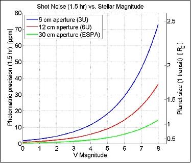
Legend to Figure 1: The right vertical axis shows detectable planet size (in units of Earth radius) in a single transit.
Spacecraft
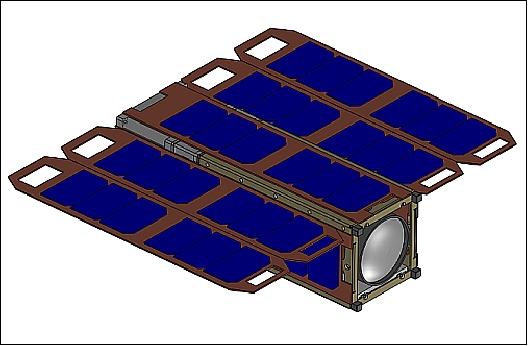
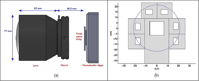
A 3U CubeSat form factor was selected for the mission using deployable solar arras in a so called “table” configuration. In this design, five 10 cm x 30 cm panels (four deployed, one body-mounted) form a surface that generates a power of 35 W. The table configuration is very advantageous over other geometries (such as a deployable “cross” configuration) because it offers an additional power margin and the geometry of the panels with respect to the optics prevents the lens from viewing the Earth during orbital daylight, which can heat the detector. In addition, the spacecraft must reorient itself during each orbital dawn and dusk, and the table configuration results in smaller slew maneuvers.
The project is using COTS (Commercial-off-the-Shelf) components whenever suitable to comply with the low-cost requirement of the mission.
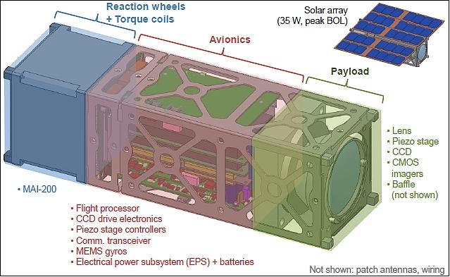
Bus structure: An off-the-shelf chassis of Pumpkin Inc. has been modified to provide the structure to hold all of the components within the standard 3U CubeSat volume of 10 cm x 10 cm x 34 cm. The total mass of the spacecraft is ~ 5.5 kg.
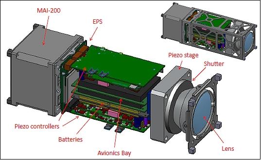
The spacecraft itself is composed of three similarly sized “modules” each with a different function (Figure 3). The aft end of the spacecraft houses a commercially available reaction wheel and torque coil unit that provides coarse attitude control. The other end houses the payload, which consists of the lens, hybrid focal plane containing multiple imagers, and two-axis piezoelectric nano-positioning stage. The piezo stage is used for fine image stabilization, translating the focal plane in two axes to cancel residual pointing errors that the reaction wheels are unable to correct. Between the reaction wheels and payload is the avionics module housing the batteries, charging and power distribution board, modem, and single board computer.
The avionics portion of the spacecraft resembles a standard CubeSat stack of PC-104 printed circuit boards communicating through a common header. Standoffs and brackets affix the avionics stack to a skeletonized chassis wall that also serves as the mounting point for solar panels and the MAI-200.
The payload module is a separate structural element that mates with the combined avionics/reaction wheel “bus” module. The payload module contains additional fixtures for mounting the piezo electric stage and lens, both of which are fairly massive. Furthermore, the payload module contains sensitive optically-toleranced components. The ability to mate and de-mate the payload allows for camera integration and testing to occur independently of the bus. Once the payload and bus modules have been separately integrated and tested, the spacecraft will be assembled for system-level verification. This modularity also allows the flight payload module to be tested with an engineering bus module prior to spacecraft integration and vice versa.
Thermal control: The baseline thermal control scheme is passive, making judicious use of coatings, multi-layer insulation, and radiating surfaces to dissipate heat away from the imagers. Thermal control was an important driver for the selection of a CMOS imager for science over a CCD, which typically has greater sensitivity to thermal variations and higher dark current at the expected focal plane temperatures in LEO.
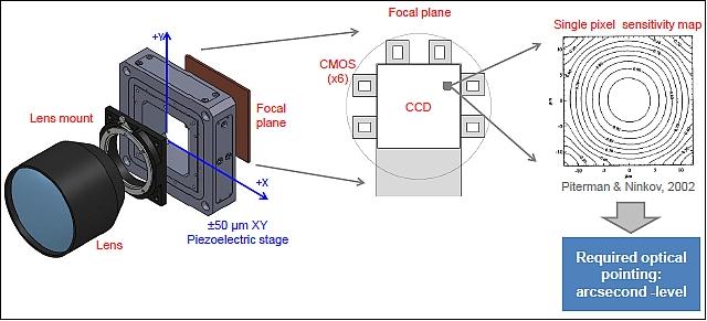
ADCS (Attitude Determination and Control Subsystem): To achieve the photometric precision required to detect Earth-sized exoplanets, the target star must remain on the same position on the detector to within a fraction of a pixel. This stems from the fact that the CCD response changes both within and between pixels. Movement of the star on the CCD, even less than a pixel, can cause enough variation of measured photons to mask the signature of Earth-sized exoplanets. 10) 11)
Based on extensive analysis, there is a requirement of restricting the target star motion to 0.14 pixels (3σ) or 5.0 arcsec in the cross-boresight attitude axes (3σ). This jitter level directly corresponds to a noise level of the measured brightness of the target star and therefore the detectable size of any transiting exoplanets. If this requirement can be met, the analyses show that Earth-sized exoplanets can be detected around stars down to 4th magnitude.
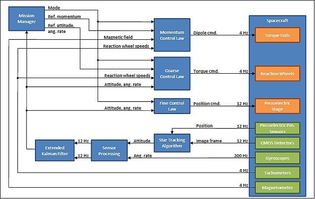
The ADCS implementation uses a two-stage pointing control mechanism:
1) Coarse pointing: Reaction wheels < 120 arcsec 3σ)
2) Fine pointing: Piezoelectric stage (5-10 arcsec 3σ)
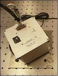
Use of miniature reaction wheels of MAI (Maryland Aerospace Inc.). The MAI-200 device has a size of 7.6 cm x 7.6 cm x 7.6 cm and a mass of 0.763 kg.
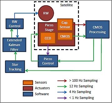
Reaction wheels provide coarse control down to a certain deadband while torque coils desaturate the reaction wheels periodically. Fine control is provided by a piezoelectric stage, which translates the focal plane (orthogonal to the boresight axis) to stabilize the image further (Figure 6). The CMOS detectors are used to image the guide stars around the target star, which are then centroided, corrected by the piezoelectric position sensors, and matched against a star catalog to determine the satellite’s attitude. Gyroscope measurements provide information on the satellite’s angular rate. These measurements are filtered and downsampled to match the rate of the CMOS detectors. In addition, processing delays from the attitude measurements of the CMOS detectors are compensated. Both the gyroscope and CMOS detector attitude measurements are then combined in an extended Kalman filter (Ref. 10).
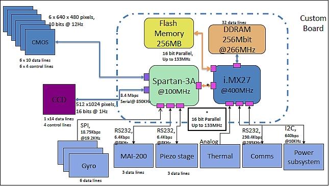
Avionics: A 32-bit PIC-32 microcontroller, FPGA, SDRAM and flash memory form the avionics subsystem. The architecture consists of a radiation tolerant FPGA, dedicated to processing the CCD and CMOS images while the embedded microcontroller handles all other processes including the ADCS estimation and control loops.
The image processing task is a main driver of the avionics architecture. The PIC32 microcontroller augments the FPGA and provides computing for the attitude control loop, along with communications handling and housekeeping functions. ExoplanetSat will use flash memory to store science and telemetry data for later transmission to the ground, and SDRAM for temporary storage of image data being processed by the FPGA.
EPS (Electrical Power Subsystem). EPS is comprised of the following components:
• Modified Clyde Space 3U CubeSat EPS with the following bus voltages: –3.3 V, 5 V, 12 V
• Pumpkin solar wings
- 4 deployable solar panels, 2 body mounted
- Each panel contains 7 Spectrolab UTJ (Ultra Triple Junction) solar cells with an efficiency of 28.3%.
• A semi-custom flat lithium-polymer battery from Clyde Space is used for energy storage. To maintain a depth of discharge of 20%, the battery stack has 70 Whr of capacity.
The average power required from the solar panels during orbital day is 28.5 W, which accounts for the attitude control subsystem, avionics, communications, and battery charging.
The solar panels will lie flat against the spacecraft while in the P-POD and passively spring open upon release from the carrier. During orbital daylight, the spacecraft will be oriented so that the deployed solar cells directly face the Sun, maximizing the charging rate. In addition to the deployed solar panels, the spacecraft will have a set of body-mounted 10 cm x 30 cm solar panels. The purpose of these body-mounted cells is to provide power during spacecraft de-tumbling after deployment or in the event of a loss of attitude control. Power will be regulated by an Electrical Power Subsystem (EPS) board from Clyde Space and stored by a bank of 8 lithium-cobalt cells.
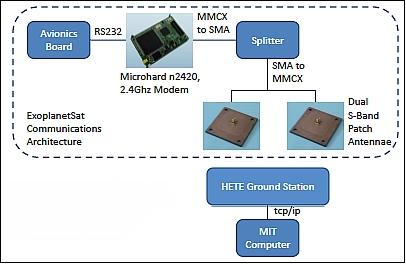
RF communications: The communications subsystem consists of two patch antennas connected to one 900 MHz model via a splitter. The antennas are oriented at right angles to each other to increase coverage and prevent loss of communication due to tumbling (loss of attitude control). With limited computing and data storage resources, data downlink of 13.4 Mbit per orbit is required. This data total accounts for all science imaging as well as telemetry and margin.
An S-band transceiver with an omnidirectional antenna and a patch antenna will provide the communication link to the existing HETE-2 (High Energy Transient Explorer-2) mission ground stations located at MIT and those of its international partners. These are located along a roughly equatorial ground track in Kwajalein (Micronesian island, Pacific), Singapore, and Cayenne (French Guiana).
The requirement of minimal onboard processing still allows some steps to be taken to reduce data storage and downlink requirements. As mentioned previously, ExoplanetSat will store only windowed portions of the detector around stars of interest. Within limits, these single integration-long (e.g. 30 second) “postage stamps” can be co-added to form longer cadence data (e.g., 5 minute samples) to achieve reasonable downlink data volumes.
Launch
A launch of ExoplanetSat is scheduled for 2013. In January, 2011, the ExoplanetSat mission was selected as a secondary payload under the NASA CubeSat launch initiative (ELaNa program) in January 2011.
ExoplanetSat will be loaded into a P-POD (Poly-Picosatellite Orbital Deployer) system as a secondary payload and deployed once the nominal orbit is attained.
Orbit: Low-inclination circular orbit, altitude ~ 650 km, inclination = ?
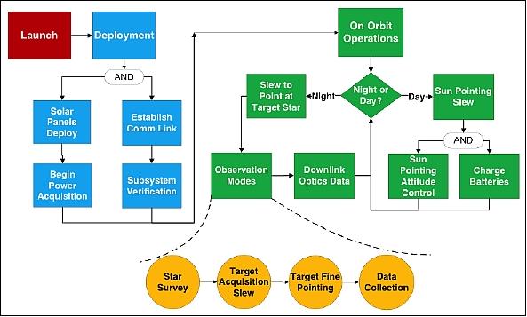
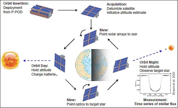
Concept of operations: From a low inclination LEO (Low Earth Orbit) at an altitude of ~ 650 km, ExoplanetSat will observe its target star when visible during orbital night. Observation during orbital day is precluded due to thermal, power, and lighting constraints. An Earth-twin transit across the center of a star would last 13 hours, thus the observing cadence from low-inclination LEO (i.e. roughly 30 minutes of orbital night followed by roughly 60 minutes of orbital day) is sufficient to detect such an event. During orbital dawn, the spacecraft will reorient itself to point the solar panels toward the sun. Likewise, during orbital dusk the spacecraft will slew to re-acquire the target star.
Sensor Complement (Camera)
The optical camera uses a lens with an aperture of 60 mm along with CCD and co-mounted CMOS detectors.
• Zeiss 85 mm f/1.4 SLR (Single Lens Reflex) camera lens
• Science: back-illuminated frame transfer CCD (1k x 1k with 13.3 µm pixels, 2 e- rms read noise, 12.5 e-/pixel/s dark current at 0ºC and 12.5º diagonal FOV)
• Star tracking: Tiled CMOS sensors (2.6k x 1.9k with 1.3 µm pixels).
The lens selection process took into account several competing design parameters. The photon collection capability is a primary consideration given the photometric nature of the mission; hence, large aperture (i.e. low f-number) lenses were given priority. Because the aperture diameter increases with focal length for a constant f-number, longer focal length lenses were also prioritized. Volume limitations were also a concern, with the outer diameter of the lens being no larger than 9 cm in order to maintain volume margin in the 10 cm CubeSat envelop. For this same reason, only 35 mm format lenses were considered.
Medium format lenses have a larger light spot and therefore provide additional focal plane area and reduced vignetting. However, the flange focal distance (FFD, the distance from lens mount to image plane) on medium format lenses is much larger than for 35 mm format lenses, making the entire lens assembly prohibitively large (Ref. 2).
Key innovations of ExoplanetSat include combining the science and star camera optics, a compact modular payload design, and the use of a two-stage control architecture.
Camera | COTS model equivalent | Zeiss Planar T 1.4/85 |
Lens | Focal length | 85 mm |
F-number | 1.4 | |
FOV | 28.6º (full cone) | |
Elements | 6 | |
Science/Star camera imager | Format | 1024 x 1024 pixels |
Pixel size | 18 µm | |
FOV (diagonal) | 17.3º (full cone) | |
Well capacity | 100,000 e- | |
Quantum efficiency x fill factor | 0.45 | |
Plate scale | 43.7 arcsec/pixel |
The primary science data product for ExoplanetSat is time-indexed windowed “postage-stamp” frames of the target star, comparison stars, and relatively empty portions of the sky for background signal estimation. The optimum integration time is a function of target star brightness and image size (the nominal PSF size is defocused to 5 pixels full-width half maximum). The maximum integration time will be on the order of 30 seconds. Once received on the ground, the time-indexed images will undergo a data processing pipeline not unlike that of the Kepler mission to remove systematic noise and produce light curves for transit identification
Related Missions
There are several current and planned photometry missions that are similar to ExoplanetSat, however none of them use the CubeSat form factor. This section describes these other efforts briefly and identifies the scientific or technical aspects of the ExoplanetSat mission that distinguishes it from them (Ref. 9).
• NASA’s Kepler mission was launched in March 2009 and has been continuously monitoring a field of 150,000 stars in an effort to detect transiting exoplanets down to Earth-sized. The requirement on Kepler’s photometric noise is 20 ppm over 6.5 hours for a V=12 star. This mission has been enormously successful and has reported its first planet discoveries. The Kepler mission, however, was designed to conduct a statistical census of the frequency of Earths in the Galaxy, not necessarily to permit detailed follow-up observation. Most of the target stars in the Kepler field are in fact too faint to allow follow-up studies. By focusing on a brighter set of target stars, ExoplanetSat will enable subsequent characterization of any exoplanets detected.
• MOST (Microvariability and Oscillations of Stars) is a Canadian microsatellite mission to conduct astroseismology measurements on stars down to V=5.5. Launched in June 2003, the spacecraft is the size of a suitcase (65 cm x 65 cm x 30 cm) and has a mass of 54 kg. The payload consists of a 150 mm aperture telescope and CCD for photometry with a signal-to-noise ratio (SNR) of 8300 (120 ppm) for a minute long exposure. MOST has shown meaningful science return and has, for example, been used to measure timings for transiting exoplanets in order to infer the presence of other planets.
• BRITE (BRIght Target Explorer) constellation: BRITE is a nanosatellite constellation of six spacecraft under development by researchers in Canada, Austria and Poland (each nation provides 2 spacecraft). The first two spacecraft of Austria will be launched in Q1 2012. The first spacecraft of Poland is due for launch in the fall 2012, while the second satellite of Poland and the two Canadian nanosatellites are planned for launch in 2013.
The objective of the photometry constellation is to measure the stellar variability of the brightest stars. The mission will achieve 20 ppm differential photometry on timescales of one month for stars down to V=3.5. Aside from different target star spectral types (O, B for BRITE and G, K for ExoplanetSat) and different science (stellar evolution for BRITE, exoplanets for ExoplanetSat), the two missions differ in several technological areas. The BRITE spacecraft bus is larger than that of a CubeSat (measuring 20 cm x 20 cm x 20 cm) and their science telescope aperture (30 mm diameter) is smaller than that of ExoplanetSat’s (60 mm diameter). The BRITE star camera and science optics are separate, while on ExoplanetSat they are combined. Finally, the attitude determination and control subsystems between the two spacecraft differ in terms of architecture (reaction wheels for BRITE, reaction wheels plus piezo stage for ExoplanetSat) and pointing precision (1.5 arcminute for BRITE, 10 arcseconds for ExoplanetSat).
References
1) Matthew W. Smith, Sara Seager, Christopher M. Pong, SungyungLim, Matthew W. Knutson, Timothy C. Henderson, Joel N. Villaseñor, Nicholas K. Borer, David W. Miller, Shawn Murphy, “ExoplanetSat:A Nanosatellite Space Telescope for Detecting Transiting Exoplanets,” 8th Annual CubeSat Developers’ Workshop, CalPoly, San Luis Obispo, CA, USA, April 20-22, 2011, URL: http://www.cubesat.org/images/2011...
2) Matthew W. Smith, Sara Seager, Christopher M. Pong, Jesus S. Villaseñor, George R. Ricker, David W. Miller, Mary E. Knapp, Grant T. Farmer, Rebecca Jensen-Clem, “ExoplanetSat: Detecting transiting exoplanets using a low-cost CubeSat platform,” Proceedings of SPIE, 'Space Telescopes and Instrumentation 2010: Optical, Infrared, and Millimeter Wave,' edited by Jacobus M. Oschmann, Mark C. Clampin, Howard A. MacEwen, SPIE, Vol. 7731, San Diego, CA, USA, June 2010, doi:10.1117/12.856559, URL: https://dspace.mit.edu/handle/1721.1/61644
3) Rebecca Jensen-Clem, Joe McCarter, “Exoplanet Observations with CubeSats,” URL: http://svcp.jpl.nasa.gov/meetings/2011/xs/032401/JPL_Final.pdf
4) http://www.axelspace.com/missionideacontest/...
5) “Nanosatellite Will Look for Alien Worlds,” MIT technology review, May 16, 2011, URL: http://www.technologyreview.com/computing/37577/?a=f
6) Matthew W. Smith, Sara Seager, ChristopherM. Pong, SungyungLim, Matthew W. Knutson, Timothy C. Henderson, Joel N. Villaseñor, Nicholas K. Borer, David W. Miller, Shawn Murphy, “ExoplanetSat:A Nanosatellite Space Telescope for Detecting Transiting Exoplanets,” CubeSat Developers’ Workshop, April 20-22, 2011, San Luis Obispo, CA, USA, URL: ftp://ftp.astro.ufl.edu/pub/bbolin/SmallSats/CubeSats/ConferencesandWorkshops/...
7) “NASA Announcement of CubeSat Launch Initiative,” July 30, 2010, URL: http://www.nasa.gov/pdf/...
8) “NASA’s CubeSat Launch Initiative,”URL: http://www.nasa.gov/directorates/somd/home/CubeSats_initiative.html
9) Matthew W. Smith, Sara Seager, Christopher M. Pong, Matthew W. Knutson, David W. Miller, Timothy C. Henderson, Sungyung Lim, Tye M. Brady, Michael J. Matranga, Shawn D. Murphy, “The ExoplanetSat Mission to Detect Transiting Exoplanets with a CubeSat Space Telescope,” Proceedings of the 25th Annual AIAA/USU Conference on Small Satellites, Logan, UT, USA, Aug. 8-11, 2011, paper: SSC11-XII-4
10) Christopher M. Pong, Sungyung Lim, Matthew W. Smith, David W. Miller, Jesus S. Villaseñor , Sara Seager, "Achieving high-precision pointing on ExoplanetSat: initial feasibility analysis,” Proceedings of SPIE, 'Space Telescopes and Instrumentation 2010: Optical, Infrared, and Millimeter Wave,' edited by Jacobus M. Oschmann, Mark C. Clampin, Howard A. MacEwen, SPIE, Vol. 7731, San Diego, CA, USA, June 2010, doi: 10.1117/12.857992, URL: https://dspace.mit.edu/bitstream/handle/1721.1/60940/Pong-2010-Achieving%20high-precision%20pointing%20on%20ExoplanetSat%20Initial%20feasibility%20analysis.pdf?sequence=2&isAllowed=y
11) C. M. Pong, M. W. Smith, M. Knutson, S. Lim, D. W. Miller, S. Seager, J. S. Villasenor, S. D. Murphy, “One-arcsecond Line-of-Sight Pointing Control on ExoplanetSat, a Three-Unit CubeSat,” Proceedings of the 34th AAS Guidance and Control Conference, Breckenridge, CO, USA, Feb. 4-9, 2011.
The information compiled and edited in this article was provided by Herbert J. Kramer from his documentation of: ”Observation of the Earth and Its Environment: Survey of Missions and Sensors” (Springer Verlag) as well as many other sources after the publication of the 4th edition in 2002. - Comments and corrections to this article are always welcome for further updates (eoportal@symbios.space).