EDRS
Non-EO
Quick facts
Overview
| Mission type | Non-EO |
EDRS (European Data Relay Satellite) Constellation / SpaceDataHighway
Launch Mission Status Space Segment Laser Communication Terminal Ground Segment EDRS Services References
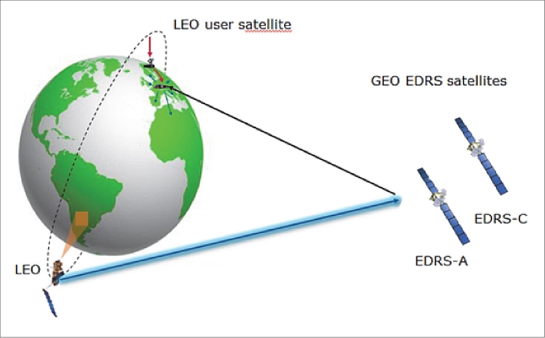
EDRS is an ESA project within the ARTES-7 (Advanced Research in Telecommunications Systems) program, a constellation of two geostationary data relay satellites, intended to provide links to satellites in LEO , and possibly other spacecraft, enabling real-time communications between these spacecraft and their respective Control Center.
ESA initiated already a precursor data-relay oriented program with the development and launch of Artemis in 2001. Artemis has demonstrated the many operational and performance benefits that the availability of a data-relay satellite offers. In the meantime, the demand for real-time high volume files is expected to increase dramatically with the beginning of operation of the Copernicus (formerly GMES) Sentinel system and future Earth observation and other missions. At the same time, the capacity of optical intersatellite links and their reduction in terms of mass and power requirements have jumped forward by at least one order of magnitude, as also radio systems have improved.
The EDRS program aims to create a new type of satellite services. It intends to bring the development and implementation of the system to a sufficiently mature stage, so that the resulting services can be provided by a satellite operator on a commercial basis. 1) 2)
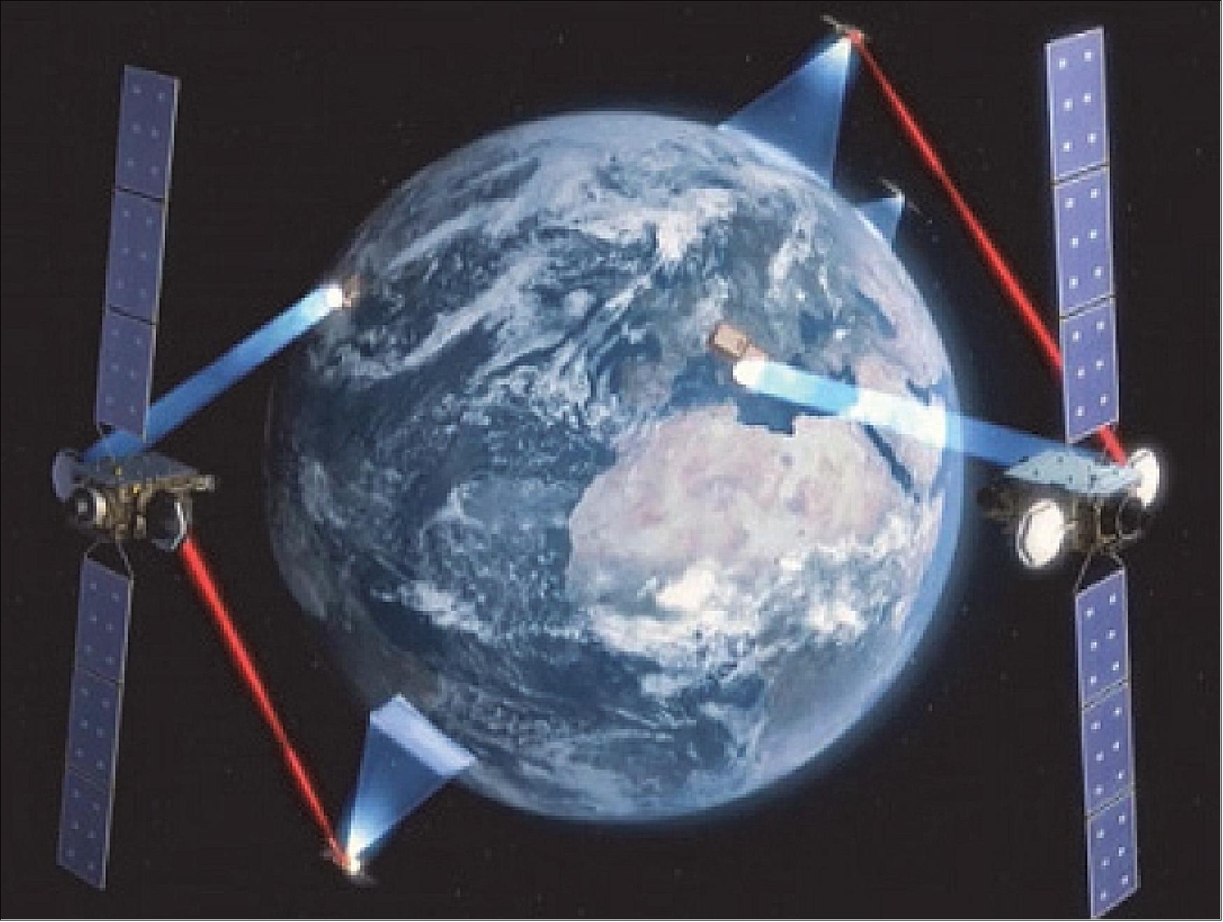
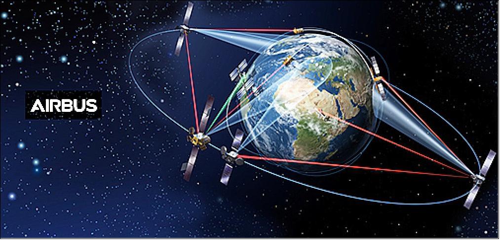
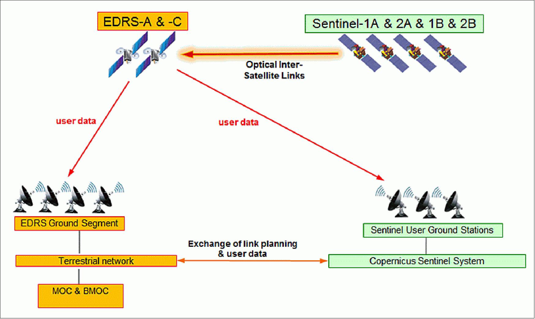
Legend to Figure 1: Various LEO spacecraft optically uplink their data to GEO stations which feed the data via conventional Ka-band links to the ground segment.
There are a number of key services that will benefit from this systems infrastructure right from the start:
• Earth Observation applications in support of a multitude of time-critical services, e.g. monitoring of land-surface motion risks, forest fires, floods and sea ice zones
• Government and security services that need images from key European space systems such as the Copernicus (formerly GMES) program
• Rescue teams that need Earth observation data in disaster areas
• Security forces that transmit data to Earth observation satellites, aircraft and unmanned aerial observation vehicles, to reconfigure such systems in real time
• Relief forces that operate among their units in the field and require telecommunication support in cut-off areas.
With the implementation of the joint European Commission/ESA Copernicus program, it is estimated that the European space telecommunications infrastructure will need to transmit a few TB (terabyte) of data every day from space to ground. The present telecommunications infrastructure is challenged to deliver such large data quantities quickly, and conventional means of communication may not be sufficient to satisfy the quality of service required by users of Earth observation data. 3)
To fulfil that demand, EDRS will become the first operational European data relay system (Figure 1) aiming at improving the quality of the data service and thereby enhancing the operational reliability and independence of European and Canadian space infrastructures such as the joint European Commission / ESA Copernicus initiative, and many national space assets. In particular, the objectives of ESA's EDRS program are:
• Provide ESA with the necessary data relay and related services via satellite. The Copernicus program will be the first customer of the EDRS service (Sentinel 1A/B and 2A/B LEO satellites). Hence, priority is currently given to the provision of services to the Copernicus/Sentinel users, given the fact that their needs are more mature and the associated timing is defined. However, the long-term objective for the EDRS program is to provide full and global data relay services to user communities related to ESA and partners of ESA.
• Foster the development of the satellite data relay services market through the exploitation of the infrastructure with commercial / institutional users beyond ESA.
• Support the standardization and adoption of optical and Ka-band data relay technology by means of the availability of technological solutions for the EDRS infrastructure as well as for the user community (Earth observation satellites, UAVs, etc.).
• Achieve a cost efficient program through a PPP (Public Private Partnership) scheme with satellite operators / service providers for the development of the infrastructure.
Unlike other ESA programs, the objective of EDRS is to develop a commercially sustainable data relay service, rather than developing only the necessary technical infrastructure (satellite and/or ground segment). Consequently, support to the adoption of EDRS by users beyond Copernicus is an important element of the program.
Events/milestones on the way toward EDRS realization
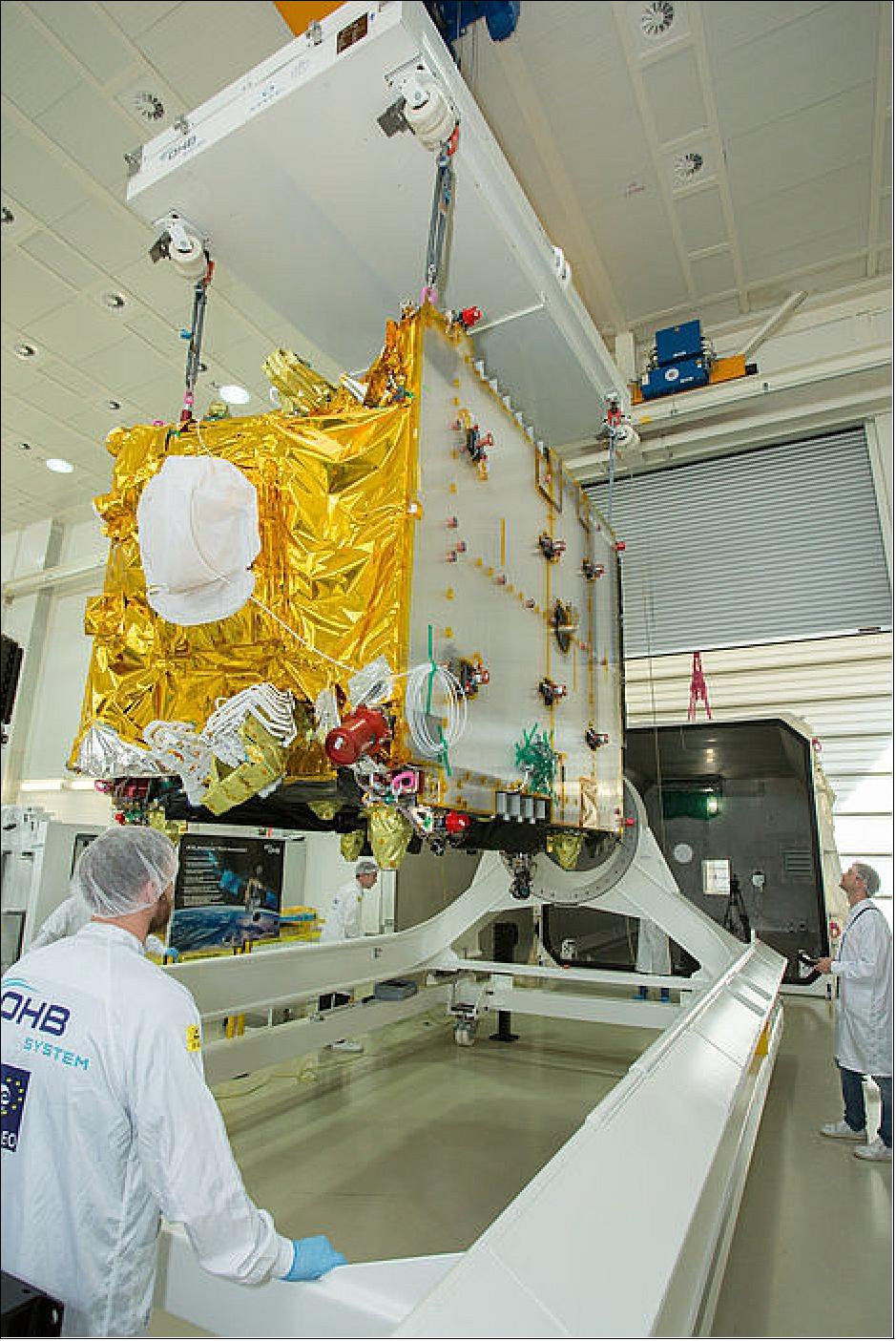
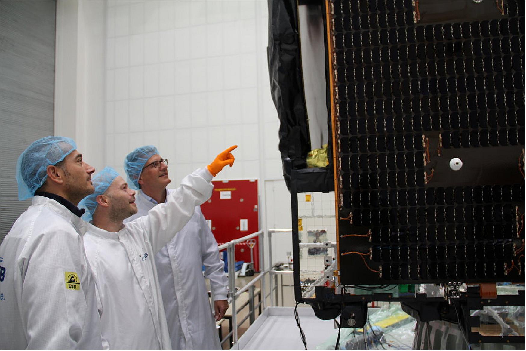
• August 1, 2019: The “brain” (onboard computer) of the latest satellite, called EDRS-C, was delivered from RUAG Space to the satellite builder OHB System AG. The onboard computer controls and monitors the payload of the satellite and many other subsystems. 4)
- Additionally, thermal Insulation from RUAG Space protects the satellite from cold and heat in space. The insulation is comprised of several layers of metal-evaporated polyimide film that is thinner than a human’s hair. Optical Solar Reflectors from RUAG Space deliver additional heat protection. The mirrors help to reject the excessive heat created by the spacecraft into space to keep the satellites payload at perfect operating temperatures. RUAG Space is Europe's market leader in thermal insulation for satellites. Also, the central tube for the satellite was produced by RUAG Space.
- Peter Guggenbach, CEO RUAG Space, said the company's high quality computer products are designed to reliably fulfill their tasks in a very harsh environment. The compact satellite management unit represents a highly integrated and efficient solution providing both the command and control of the spacecraft and the attitude and orbit control functions. The equipment has been the basis for delivery of further central computers to a series of meteorological and telecommunication satellites. Our products are key to the success of the mission and the firm's payload fairings have been implemented successfully in almost 300 rocket launches to date.
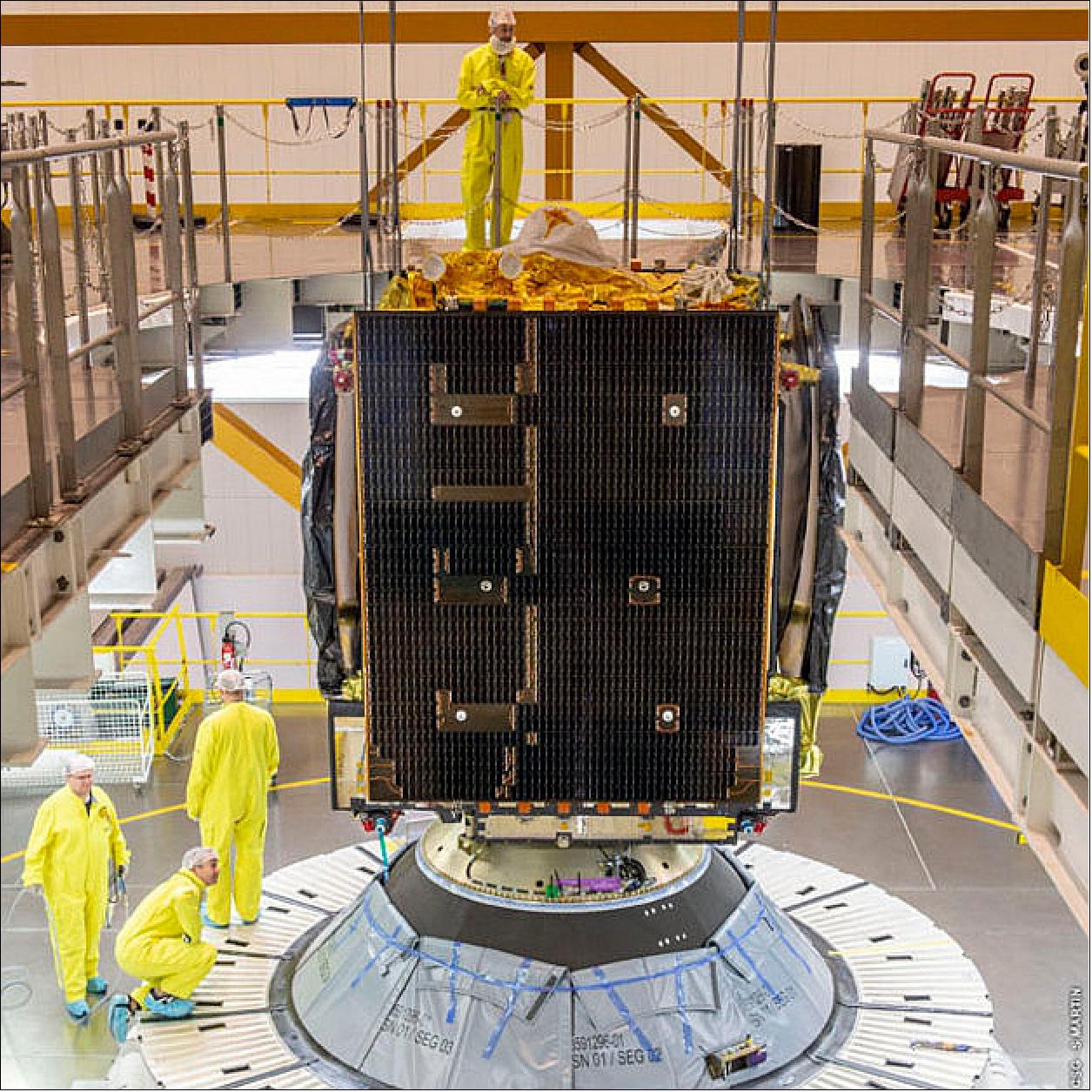
• July 30, 2019: The second satellite to join the constellation that forms the European Data Relay System (EDRS) has been mated with its launch vehicle. 5)
- The EDRS-C satellite is due for launch on 6 August from Europe’s Spaceport in Kourou, French Guiana, aboard an Ariane 5 rocket.
- EDRS enables people to observe the Earth almost live, accelerating responses to emergency situations and spurring the development of new services and products that create jobs and increase prosperity.
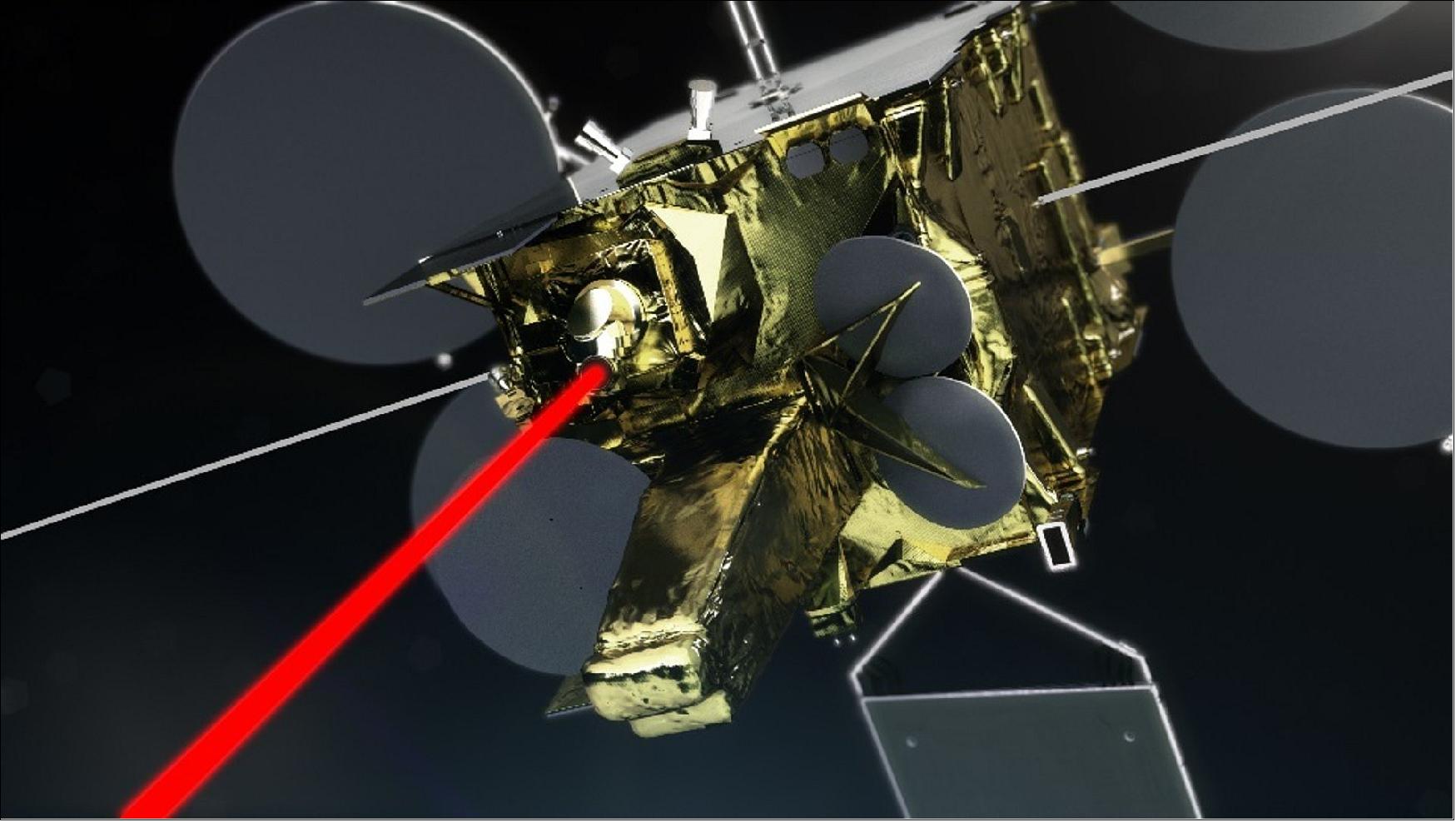
- Dubbed the ‘SpaceDataHighway’ by its private operator, Airbus, EDRS uses innovative laser technology to dramatically cut the time needed for Earth observation satellites to deliver information to the ground.
- Instead of sending data from Earth observation satellites to the ground – which introduces delays of up to 90 minutes, as the information can only be transmitted when the satellite is in line-of-sight with the ground station – the system sends the data away from the Earth to the EDRS satellites that are in a higher, geostationary orbit.
- The EDRS satellites are in constant contact with their ground stations and can beam the data back down to Earth almost immediately.
- The satellites can transmit data at a rate of up to 1.8 Gbit/s.
- EDRS is a new, independent European satellite system, and is a public–private partnership between ESA and Airbus as part of ESA’s efforts to maximize the benefits to industry by taking an efficient management approach tailored to commercial best practices.
- “When EDRS-C joins its sister satellite EDRS-A in orbit, it will boost the capacity and reach of the system, which will enable companies in Europe and Canada to develop new services and products,” says Michael Witting, EDRS project manager at the European Space Agency.
- “ESA is helping to boost innovation by de-risking partners investments to meet market needs.”
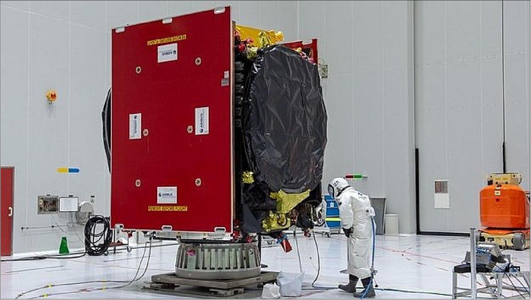
• July 26, 2019: The second satellite to join the constellation that forms the EDRS (European Data Relay System) has finished fuelling and is days away from launch. 6)
• May 6, 2019: The EDRS-C satellite, the second node of the SpaceDataHighway network (also known as EDRS), will be launched into geostationary orbit at 31° East on 24 July 2019 by an Ariane 5 launcher. Once positioned above Europe, it will provide redundant back-up for the SpaceDataHighway system, double transmission capacity and be able to relay the data from two observation satellites simultaneously. 7)
- This second satellite will be joining EDRS-A which transmits on a daily basis the images of Earth acquired by the Copernicus program’s four Sentinel observation satellites. Since it entered service in late 2016, it has achieved more than 20,000 laser connections. The reliability rate has reached 99.5%, and these successful connections have downloaded more than 1 petabyte (1015 bytes) of data.
- “This milestone in the SpaceDataHighway represents a significant step forward in terms of capability. It’s an exciting time to see the next generation of secure connectivity develop,” said Evert Dudok, Head of Communications, Intelligence & Security at Airbus Defence and Space.
- The SpaceDataHighway is the world’s first ‘optical fibre’ network in the sky based on cutting-edge laser technology. It is a unique network of geostationary satellites permanently fixed over a network of ground stations that can transmit data at a rate of 1.8 Gbit/s.
- SpaceDataHighway satellites can connect to low-orbiting observation satellites at a distance up to 45,000 km, intelligence UAVs or mission aircraft via laser. From its position in geostationary orbit, the SpaceDataHighway system relays data collected by observation satellites to Earth in near-real-time, a process that would normally take several hours. It thus enables the quantity of image and video data transmitted by observation satellites to be tripled and their mission plan to be reprogrammed at any time and in just a few minutes.
- A third communication node is to be positioned over the Asia-Pacific region by around 2024. Equipped with three laser terminals, EDRS-D will significantly increase the system’s communication capacity and considerably expand its coverage.
- From 2021, the Pleiades Neo Earth observation satellites will begin to use the SpaceDataHighway. As of 2019, the system will also provide a fully European broadband communication service to the Columbus module of the International Space Station (ISS).
- The SpaceDataHighway is a PPR (Public–Private Partnership) between the European Space Agency (ESA) and Airbus, with the laser terminals developed by Tesat-Spacecom and the DLR German Space Administration. Airbus owns, operates and provides commercial services for the SpaceDataHighway. The EDRS-C satellite platform supplied by OHB System AG will also be carrying a payload from Avanti Communications.
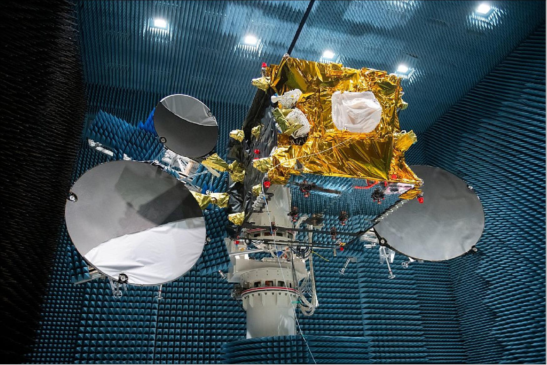
• April 23, 2019: The latest component in the European Data Relay System (EDRS) has passed another important milestone. Tests have successfully concluded on the antennas of the EDRS-C satellite. 8)
- EDRS—dubbed the “SpaceDataHighway” by its private operator, Airbus—allows the transmission of large quantities of data with reduced delay, using laser communication technology.
- Earth-observing satellites typically circle the planet every 90 minutes and normally relay the information they have acquired only when they are in a direct line-of-sight with a ground station.
- With EDRS, the Earth-observing satellites can transmit this information via laser links to the relay satellites, which are in much higher orbits and are in constant sight of their ground stations.
- Once EDRS-C has passed its final tests, it will be shipped to Kourou in French Guiana for launch in the summer.
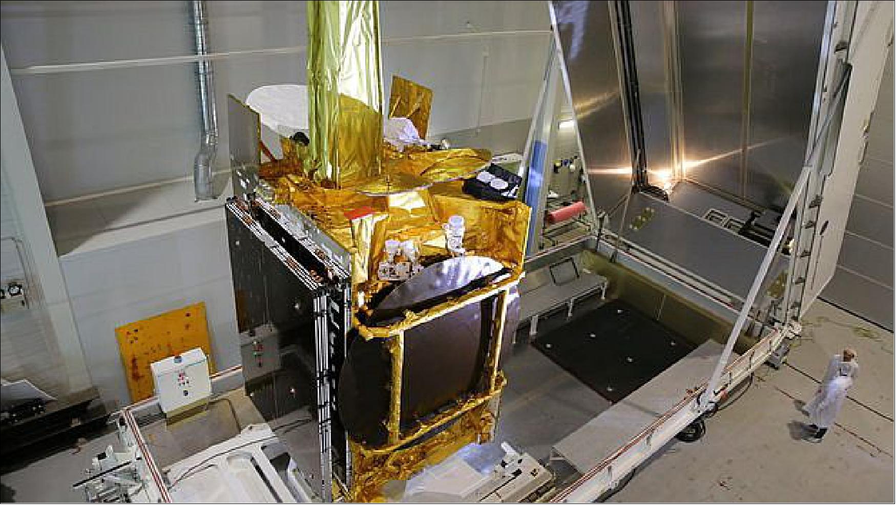
• April 16, 2019: EDRS-C is currently in the anechoic test chamber at the CATR (Compact Antenna Test Range) at Airbus in Ottobrunn Germany, where the satellite is currently undergoing verification of the antennas performance before shipment to its launch site in Kourou in June. The European Data Relay System (EDRS) is designed to relay data between satellites in low orbit and Earth via satellites in geostationary orbit. It allows transmission of large quantities of data with reduced delay, using innovative laser communication technology. 9)
- EDRS will form the ‘SpaceDataHighway’ for Europe, made up of one hosted data-relay payload (EDRS-A), one data-relay payload on a dedicated satellite (EDRS-C) and a dedicated ground segment.
- EDRS dramatically increases the speed with which low-orbiting satellites can deliver their information to users, by relaying their data via the EDRS payloads in geostationary orbit to European ground stations. With EDRS ground stations in Redu (BE), Harwell (UK) and two in Weilheim (DE) plus the Italian Space Agency’s user ground station in Matera (IT), EDRS is the first truly European laser communications network.
• June 20, 2018: ESA’s laser satellite EDRS-C has settled at its new home in Munich for the last tests before launch. This final set will make sure the satellite and its optical payload can withstand the challenging conditions of lift off and subsequent life in space once launched next year. 10)
- The European Data Relay System is a unique public–private partnership between ESA and Airbus, with EDRS-C being the first dedicated satellite. The first node, EDRS-A, was launched to geostationary orbit in 2016 as a hosted payload.
- The system – nicknamed the SpaceDataHighway – provides data relay between low orbiting satellites and the EDRS nodes over optical links, with the information sent down to Europe in near-real time.
- EDRS-C arrived at IABG Munich after a day and a half on the road across Germany at the end of May, from its previous home at OHB System AG in Bremen.
- EDRS-C passed several integration and testing milestones at OHB, including the platform and payload mating, and the installation of its Laser Communication Terminal (LCT), which was developed by Airbus subsidiary Tesat Spacecom, with support from the DLR German Space Administration.
- The LCT forms the backbone of EDRS, providing the means by which the satellites connect to their targets and collect the data. An identical terminal on board EDRS-A has now made more than 10,000 successful links to the European Union’s Copernicus Sentinels-1 and -2, relaying in excess of 500 TB of the Earth observers’ findings.
- To ensure the EDRS-C terminal is prepared for similar operational reliability, the instrument has undergone thorough alignment and health checks since being integrated with the satellite in March 2017.
- In total, the satellite as a whole was subject to and passed more than 90 tests in Bremen, which were designed to check all was working as it should as the spacecraft took shape. The results of these tests will also serve as a map of reference points to compare the satellite and its equipment’s performance to after the tests in Munich, which will put them through their paces in a simulated operational environment.
- The spacecraft is currently being prepared for the first of the set, the thermal vacuum test, which will subject it and its equipment to the intense temperature fluctuations of space, while replicating the same vacuum-like conditions.
- Michael Witting, EDRS Project Manager, said: “The shipment to IABG represents a key milestone for the project: the satellite design and integration phases are over and the testing can start. Although we and our partners have a great deal of work ahead, the satellite has done very well so far, so we are looking forward to more good performance in preparation for launch next year.”
• July 26, 2017: A long-delayed satellite carrying a laser-optical payload for intersatellite links and Ka-band broadband for Africa faces further delays because of an anomaly in its Ka-band system, government and industry officials said. The satellite, called EDRS-C by the European Space Agency, Airbus Defense and Space and the European Commission, and Hylas-3 by commercial satellite fleet operator Avanti Communications, which will operate the Ka-band service, is unlikely to launch before mid-2018, officials said. 11)
- EDRS-C/Hylas-3 is important for Airbus because it will extend the coverage and provide backup for the EDRS-A payload now in orbit on fleet operator Eutelsat’s Eutelsat 9A satellite at 9 degrees east in geostationary orbit.
- Commercial Ka-band payload issues: The latest issue relates to the Ka-band equipment provided by MDA Corp. of Canada under a July 2012 contract valued at 35 million Canadian dollars ($26 million). Officials said the equipment had been integrated into the satellite, being assembled by OHB SE of Germany. — It has since been removed and returned to MDA’s Montreal facility for rework.
- In response to Space Intel Report inquiries, MDA on June 23 issued the following statement: “The majority of the payload is integrated with the spacecraft. Relative to well-known delays in the project, MDA payload components have experienced inconsequential delays.”
- EDRS-C/Hylas-3 is being financed under a complicated relationship between Airbus, ESA, OHB and Avanti. Airbus is the prime contractor for the European Data Relay System, rebranded the SpaceDataHighway.
• ESA approved the program in November 2008 following a strong push from Germany, which is the lead investor (50% share). After more than two years of negotiations, the governments of Europe have secured the full funding package for ESA to build a data-relay satellite system whose initial customer will be the European Commission’s (EC's) Earth observation program.
• In October 2010, ESA selected Astrium GmbH (Business Unit Services) as the prime contractor and operator of the EDRS (European Data Relay System) consortium that will make these services available for the GMES (Global Monitoring for Environment and Security) program.
• In January 2011, final approval for the program was given by the Joint Communication Board, based on the mission technical baseline negotiated between ESA and Astrium, and on the funding from the Participating States. In the PPP concept, Astrium Services will operate the EDRS as a profit-making business, once the system is launched. The EC (European Commission) will be Astrium's anchor tenant, but the company will be free to seek other customers as well. 12) 13)
• In particular, ESA has selected Astrium Services to manage the development and operations of EDRS that would feature one dedicated satellite (EDRS-C) and one hosted payload (EDRS-A). Both of them will be positioned in the geostationary orbit with visibility over central Europe.
The EDRS system will be implemented in a so-called PPP (Public-Private Partnership) arrangement, an innovative structure in which ESA leads the creation of the initial system and infrastructure that is later taken over for full exploitation and further development by a commercial partner. EDRS will boost European-developed technology and make use of a cutting-edge intersatellite laser communication system as well as new data dissemination infrastructure on the ground. 14)
• On Oct. 3, 2011, ESA/TIA (Telecommunications & Integrated Applications) and Astrium Services signed a PPP contract in Paris for the development of the EDRS system. Under the terms of the agreement the partners will jointly finance the EDRS. With EDRS services starting in 2014, all suitably equipped future European Earth observation satellites will be able to perform quicker data transfers and transmit for longer periods. Astrium has the overall responsibility for designing and developing the complete space and ground infrastructure. Astrium will then acquire ownership of EDRS and is committed to its operation for the next 15 years. 15)
• On June 25, 2012, DLR, Astrium Satellites (prime contractor to ESA) and SES Astra TechCom S.A. (Luxemburg) signed contracts for large parts of the ground segment of the new EDRS. DLR has been appointed as a subcontractor by Astrium and is responsible for constructing large parts of the ground segment and for controlling the payloads on the first satellites, referred to as EDRS-A. DLR will also manage and control the EDRS-C relay satellites during routine flight operations that will last for at least 15 years. For this purpose, a dedicated EDRS control center will be developed within DLR's GSOC. The two geostationary relay satellites will transmit the data collected by the lower-orbiting Earth observation satellites to a total of four receiver antennas, which will be located on the sites of the existing ground stations at Weilheim (DLR) and Redu (Belgium), and at Harwell (United Kingdom). SES TechCom S.A. will supply the four antennas and will operate the antenna at Redu on behalf of DLR. 16) 17) 18) 19)
• The SRR (System Requirements Review) has been closed-out in July 2012. In parallel the EDRS-A PDR (Preliminary Design Review) has been successfully completed in April 2012.
• November 2012: The design of Europe’s data relay satellite system – EDRS - has been completed and approved. This marks the moment when it moves ahead with a green light from its first customer, the GMES (Global Monitoring for Environment and Security) initiative from the European Union. A design review board of senior members from ESA, Astrium and the DLR German Aerospace Center approved the entire system design: from the satellites to the support that will be required from the ground. 20)
• May 2013: OHB System AG and Astrium GmbH signed the final contract for the delivery of a satellite for the upcoming EDRS (European Data Relay Satellite System). The EDRS-C satellite, which is now being developed and built by OHB System, thus forms part of a constellation of geostationary satellites which will be receiving data from LEO satellites and transmitting it to the Earth. EDRS-C is being assembled on the basis of the SmallGEO platform, currently under development at OHB System under ESA's ARTES 11 program. 21)
• Delivery of the EDRS-A / EDRS-C payloads to corresponding satellite integrators is scheduled for the end of 2013 and for mid-2014, with a satellite launch planned for the end of 2014 and early 2016, respectively.
• October 29, 2014: The first component of Europe’s space data highway passed several critical tests this summer replicating the harsh launch and space conditions it will soon have to endure. EDRS-A, consists of three hosted packages on the Eutelsat-9B satellite for launch next year. 22)
- The first is a laser terminal capable of receiving 1.8 Gbit/s of user data from a satellite up to 45 000 km away.
- EDRS-A also carries a radio terminal that will handle up to 300 Mbit/s – a vast improvement over today’s systems.
- The third package is an ‘opportunity payload’ funded by Italy’s ASI space agency operating independently of EDRS to provide broadcasting services over Italy.
The EDRS Space Data Highway is a commercially operated data relay system created as a PPP (Public–Private Partnership) between ESA and Airbus DS. As prime contractor, the company will build, operate and co-fund the infrastructure, as well as providing the data transmission services to ESA and customers worldwide. DLR (German Space Agency) also plays a key role in the funding of EDRS and in the development and the operation of the ground segment. 50 companies in 13 European countries are involved in the EDRS consortium, allowing European space industry to stay at cutting edge of technology.
• February 2015: Following the recent decision confirming the ESA/Airbus DS partnership on the EDRS, agreement has been reached with the European Commission (EC) for the provision of EDRS services to the European Union Copernicus program. 23)
- Subsequently, ESA and Airbus DS have signed a service level agreement on 20 February 2015 to provide high-speed communications to the Copernicus Sentinel-1 and -2 dedicated missions, starting in 2015 until 2021, with an option for extension until 2028.
At the same occasion, ESA and Airbus DS also signed a service contract providing data relay capacity to other ESA and ESA partner missions in the future. As a first additional user, ESA’s Columbus module on the ISS (International Space Station) is planned to be provided with data relay services starting in 2018, which will support scientific experiments and enhance communication services to the astronauts on board the ISS.
• October 2015: EDRS-A Payload has been integrated with the spacecraft and passed successfully all tests on payload and satellite level. The satellite is now ready for launch (Ref. 58).
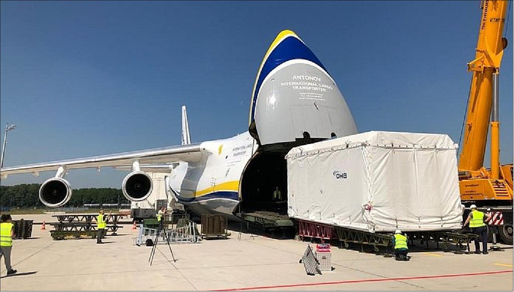
• December 9, 2015: After a year-long wait in storage for a Proton rocket to become available, the EDRS-A laser communications payload and its Eutelsat host satellite are finally at the Baikonur Cosmodrome and being prepared for launch in late January 2016. EDRS-A was packed into an Antonov plane by Airbus Toulouse, France and flown to Kazakhstan in November. 24)
- The Eutelsat-9B/EDRS-A satellite has undergone a plethora of tests to make sure it is space-ready after its launch and mission. EDRS-A’s laser terminal is essentially an autonomous state-of-the-art telescope, with mirrors to help the laser lock on to its mark in lower orbits from its own position in geostationary orbit. The moving target can be up to 45 000 km away and requires an astonishing level of precision to hit. Extreme precision requires absolute cleanliness before EDRS-A reaches orbit – any grime or speck of dust can affect the terminal’s mirrors and ability to pinpoint its target.
- Laser beams are capable of higher accuracy and capacity than radio – up to a record-breaking 1.8 Gbit/s of user data. The terminal is also fitted with a Ka-band radio transmitter to deliver the data to a ground station. The radio downlink is an important part of EDRS’s services. Like the laser element, it is a two-way link that helps EDRS customers to send commands to their satellites.
Launch: The EDRS-A payload was launched on January 29, 2016 (22:20:08 UTC) as a hosted payload on the Eutelsat- 9B communication satellite (total launch mass of 5300 kg). The launch vehicle was the Proton-M/Briz-M of Khrunichev, ILS (International Launch Services) the launch provider, and the launch site was the Baikonur Cosmodrome, Kazakhstan. 25) 26) 27) 28)
Orbit: Geostationary orbit, altitude = 35,876 km, location = 9ºE.
Launch: The EDRS-C spacecraft was launched on 6 August 2019 (19:30 UTC) on Ariane-5 ESA from Kourou. The flight, designated VA249, launched the Intelsat 39 and EDRS-C communication satellites. 29) 30)
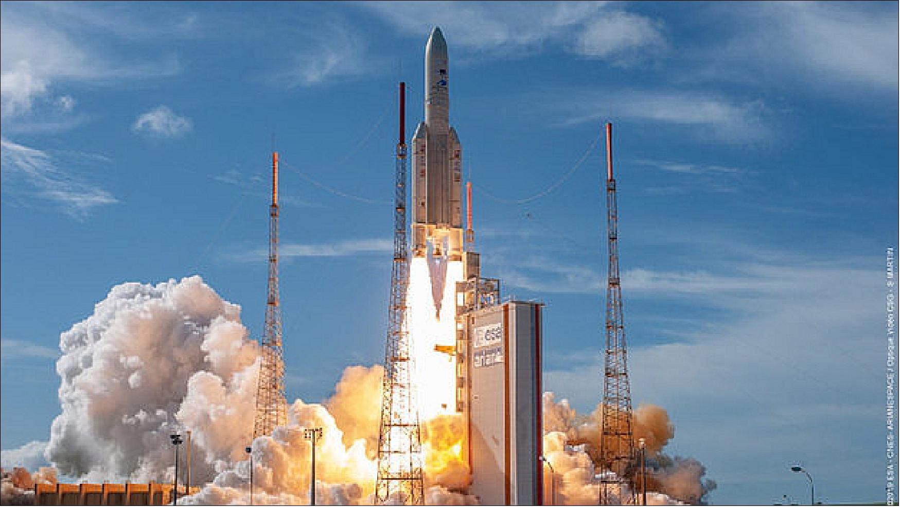
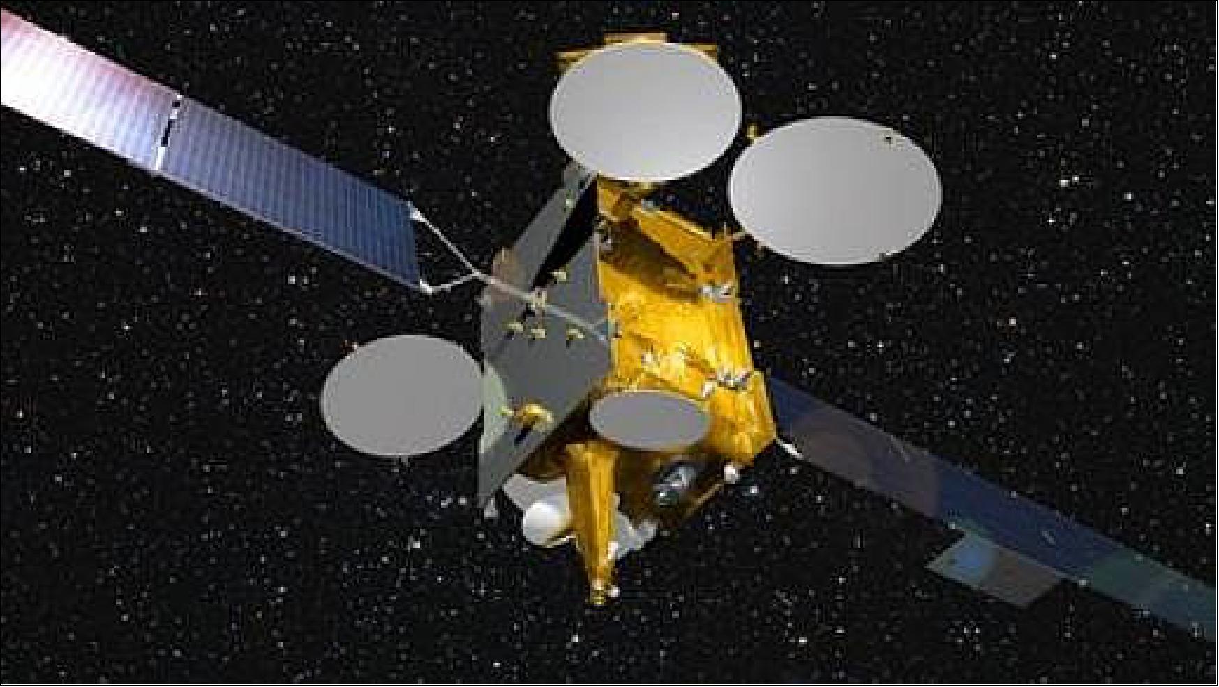
Built by SSL (a Maxar company), the Intelsat 39 satellite will replace Intelsat 902 and provide broadband networking and video distribution services in Africa, Europe, the Middle East and Asia, plus broadband connectivity for mobile users in the Indian Ocean region. — The EDRS-C satellite, built by OHB System AG, will be the second node in the European Data Relay System, a network developed by the European Space Agency and Airbus Defense and Space providing high-speed laser communications links between low-orbiting satellites and ground stations. EDRS-C also carries a hosted steerable Ka-band communications payload named HYLAS-3 for Avanti Communications. 31)
For this 105th flight of an Ariane 5, the payload lift performance to geostationary transfer orbit is approximately 10,660 kg – a total that factors in Intelsat 39 and EDRS-C, plus the launch vehicle’s dual-passenger dispenser system and satellite integration hardware.
Intelsat 39 is the mission’s upper passenger and will be released first in the flight sequence 29 minutes after liftoff. EDRS-C – to be deployed from Ariane 5’s lower passenger position – is the second node of the SpaceDataHighway network, a public-private partnership between Airbus and the European Space Agency. This spacecraft’s separation will occur 33 minutes after liftoff, completing the August 6 mission.
On March 19, 2015, Arianespace and Airbus Defence and Space reached an agreement for the launch of EDRS-C on Ariane-5 for 2018 from Kourou. 32)
Orbit: Geostationary orbit, altitude = 35,876 km, location = 31ºE.
Mission status
• June 24, 2021: Valuable data is flowing rapidly from Earth observing satellites back to the planet, thanks to the most sophisticated laser communication network ever built. 33)
- Day-and-night radar images and multispectral high-resolution images of vegetation, soil and water cover, inland waterways and coastal areas – as well as information for emergency services – are arriving back at Earth in almost real time.
- Some 50,000 links have now been established between four low-Earth orbit (LEO) satellites and the two geostationary (GEO) communication satellites that form the European Data Relay System (EDRS).
- This geostationary position – nearly 36,000 km above Earth – enables the communication satellites to maintain an almost constant connection with Earth-observation satellites, which are closer to the planet’s surface and circle the Earth approximately every 90 minutes.
- The EDRS satellites use lasers to communicate with Earth-observation satellites and beam their data back to Europe using radio-frequency transmissions in almost real time. Communication without these relay satellites would result in delays of up to 90 minutes.
- The four Earth-observation satellites communicating with EDRS are Sentinel satellites belonging to the EU’s Copernicus program. EDRS includes radio inter-satellite link capability, which will also be used to relay information from the International Space Station and other commercial satellites.
- EDRS is an independent European telecommunication satellite system, and is a Partnership Project between ESA and operator Airbus as part of ESA’s efforts to federate industry around large-scale programs, stimulating technology developments to achieve economic benefits.
- The two EDRS satellites were built by Airbus and by OHB System in Germany, under ESA’s program of Advanced Research in Telecommunications Systems.
• January 27, 2021: The EDRS (European Data Relay System) uses cutting-edge laser technology to greatly reduce the time it takes for information to be sent from low-Earth orbiting spacecraft – such as the Earth observing Sentinel satellites – to Earth. 34)
- The system makes Earth observation information available in almost real-time, which can help disaster management workers and the emergency services accelerate their responses to natural crises.
- Known as the ‘space data highway’, it currently consists of an extensive network of European ground stations and control centers, and two sister satellites: EDRS-A and EDRS-C. Both are in geostationary orbit at an altitude of around 36,000 km, far higher than low-Earth orbiting spacecraft, which typically have an altitude of below 1000 km.
- Thanks to the orbital position of the system’s satellites, low-Earth orbiting spacecraft lie within the field of view of EDRS for extended periods. At the same time, EDRS has a permanent connection to its own ground stations located on European soil.
- Traditionally, when a low-Earth orbiting satellite sends information to Earth, it must wait until it has a direct line of sight to a ground station. This can lead to delays of up to 90 minutes.
- EDRS-A relays a command to the low-Earth orbiting satellite, instructing it to point its sensors towards the area of interest on Earth. Once the data – such as an image – is acquired, it is sent to EDRS-C using laser technology. The data is then relayed to an EDRS ground station via a radio frequency link.
- EDRS is a new, independent European satellite system, and is a Partnership Project between ESA and operator Airbus. It forms part of ESA’s efforts to federate industry around large-scale programs, stimulating technology developments to achieve economic benefits.
• July 16, 2020: The second satellite in the network, EDRS-C, has now passed its user commissioning review and entered into full service. 35)
- The EDRS satellites use lasers to communicate with Earth-observation satellites and beam their data back to Europe in almost real time. Without them, there would be delays of up to 90 minutes.
- EDRS-C has joined its sister satellite, EDRS-A, and can now be used by its customers to relay information from all four Sentinel satellites that watch over Earth, capturing day-and-night radar images and multispectral high-resolution images of vegetation, soil and water cover, inland waterways and coastal areas – as well as information for emergency services.
- EDRS is a new, independent European satellite system, and is a Partnership Project between ESA and operator Airbus as part of ESA’s efforts to federate industry around large-scale programs, stimulating technology developments to achieve economic benefits.
- The EDRS-C satellite platform was built by OHB System in Germany and the laser terminals were developed by Tesat-Spacecom and the DLR German Space Administration.
• May 29, 2020: The second node in the most sophisticated laser communication network ever designed is ready to go into service. Dubbed the “SpaceDataHighway”, the European Data Relay System (EDRS) helps Earth-observing satellites to transmit large quantities of potentially life-saving data to Europe in near-real time. Its second satellite, EDRS-C, has now completed its in-orbit commissioning review and is ready to start service. 36)
- Launched on 6 August 2019, EDRS-C has since maneuvered into its geostationary orbit some 36,000 km above Earth where it has been thoroughly tested during the past six months.
- This geostationary position enables the communication satellite to maintain an almost constant connection with Earth-observation satellites that are closer to the planet’s surface and circle the Earth every 90 minutes or so.
- The EDRS satellites use lasers to communicate with Earth-observation satellites and beam their data back to Europe in almost real time. Without them, there would be delays of up to 90 minutes.
- The in-orbit commissioning review demonstrated that all EDRS-C systems perform well and that EDRS-C can link with Sentinel 2B, one of the Earth-observation satellites from the European Union’s Copernicus program.
- EDRS-C is now being tested with all four Sentinel satellites ahead of its user commissioning review, which is due to take place in a few weeks.
- Following the user commissioning review, EDRS-C will join its sister satellite, EDRS-A, as an operational node of the EDRS constellation. The latter was launched in January 2016 and has been providing communications services to the Copernicus program since November 2016.
- EDRS-A is due to relay information from the International Space Station, once the required equipment is installed on the outside of its Columbus laboratory.
- EDRS is a new, independent European satellite system, and is a Partnership Project between ESA and operator Airbus as part of ESA’s efforts to federate industry around large-scale programs, stimulating technology developments to achieve economic benefits.
- The EDRS-C satellite platform was built by OHB System in Germany and the laser terminals were developed by Tesat-Spacecom and the DLR German Space Administration.
- EDRS is designed to transmit data between LEO (Low Earth Orbiting) satellites and the EDRS payloads in geostationary orbit using innovative laser communication technology.
- Composed of a hosted payload (EDRS-A) on a commercial telecom satellite and a dedicated satellite (EDRS-C) in geostationary orbit, the system will dramatically increase the speed of data transmission for satellites in lower orbits and airborne platforms to relay their information to users on the ground. Nicknamed the 'SpaceDataHighway' by industry, EDRS complements current downlink infrastructures and allows for near-realtime services on a global scale.
- The system has Mission Operations Centers in Ottobrunn (DE) and Redu (BE), Spacecraft/Payload Control Centers in Oberpfaffenhofen (DE) and ground stations in Redu (BE), Harwell (GB) and two in Weilheim (DE).
• January 23, 2020: The second satellite in the European Data Relay System, EDRS-C, has reached its intended orbit and completed its in-orbit tests. 37)
- Dubbed the “SpaceDataHighway” by its commercial operator Airbus, EDRS uses innovative laser technology to enable Earth-observation satellites to deliver their information to users on the ground in near real-time, accelerating responses to emergency situations and spurring the development of new services and products.
- EDRS-C is the second satellite in the system and was launched on 6 August 2019.
- After being delivered into its initial orbit by an Ariane 5 launcher, EDRS-C made its way to its final geostationary orbit 36,000 km above Earth through five liquid apogee engine burns and a few relocation maneuvers.
- It has been thoroughly tested to ensure that all its components are operating as expected.
- Control of the satellite has now been handed over to Airbus. In the coming months, the performance of its laser communication terminal will be fine-tuned as part of the nominal test sequence. To do so, several links are scheduled with the Copernicus program’s four Sentinel Earth observation satellites.
- Commercial service is expected to begin in the spring.
- The satellite also hosts a commercial payload operated by British satellite operator Avanti that is about to start delivering communications services.
- EDRS is a public–private partnership between ESA and Airbus as part of ESA’s efforts to federate industry around large-scale programs, stimulating technology developments to achieve economic benefits.
- The first satellite in the EDRS network, EDRS-A, was launched in January 2016. Since then it has transmitted 1.7 petabytes of data, equivalent to binge watching almost 20,000 ultra high definition 4k films 24 hours a day for nearly four-and-a-half years.
- The data was transmitted via almost 30 000 optical inter-satellite links established with the Copernicus program’s four Sentinel Earth observation satellites.
• July 22, 2019: A Sentinel satellite is taking an image to identify dark vessels and potential oil spills and making this time-critical information available in almost real time to users thanks to the European Data Relay System (EDRS). This highly valuable capability has been successfully showcased during a live demonstration held at the headquarters of the European External Action Service in Brussels on 10 July. 38)
- “This event marks the first official live demonstration of this globally unique data relay capability based on cutting-edge laser technology able to send data over distances of 40,000 km at 1.8 Gbit/s. Connected via a live stream with the EU delegation in Tokyo, this event also allowed invited Japanese industries and institutional representatives to follow our live link session during a parallel event organized by Airbus and its business partner JSAT.” explained Mathias Schneidereit, leading the EDRS market development activities at Airbus.
- Dubbed the “SpaceDataHighway” service, the EDRS infrastructure enables Earth-observation satellites to deliver their information to users on the ground in near real-time, accelerating responses to emergency situations and spurring the development of new services and products.

- The system works by using highly precise lasers to speed up the data relay of imagery from Low Earth orbiting satellites. Without EDRS, these satellites can only dump their information when they are in direct line-of-sight with a ground station, which happens on average only every 90 minutes. With EDRS, they send their data through space via a laser link to telecommunication satellites in a higher, geostationary orbit that have a constant view of a ground station.
- EDRS is a public–private partnership between ESA and Airbus, with significant investment by the German Space Administration DLR. Besides the first long term customer Copernicus, the SpaceDataHighway data relay services will be used by Pleiades NEO from 2020 onwards.
- Evert Dudok, Executive Vice-President at Airbus, said: “The SpaceDataHighway and the EDRS service is a unique European capability. It is truly pioneering and as we saw today, it puts earth observation at our fingertips.”
- Magali Vaissiere, Director of Telecommunications and Integrated Applications at ESA, said: “EDRS has a wealth of applications. To stay ahead of the international competition, we have to make sure that EDRS meets the real needs of users and we have to keep on investing in the infrastructure itself to make it global. It will become a worldwide commercial success.”
• July 19, 2019: Airbus has agreed a five-year contract with the UK Ministry of Defence (MOD) to manage test and reference services to support the delivery and assured release of Command, Control, Communications, Computers, Intelligence, Surveillance, and Reconnaissance (C4ISR) capability for deployed operations around the globe. The contract is valued at approximately £22 million (€ 25 million). 39) 40)
- Airbus offers the UK MOD a seamless transition and delivery of a comprehensive, consistent and coherent service model for the Land Systems Reference Centre (LSRC), delivering test and reference capability to support development, integration, approval and de-risking of C4ISR systems and services.
- Airbus aims to make the LSRC the UK MOD’s centre of excellence for advice and test, ensuring that MOD networks can accommodate new applications, hardware and services. Major programs such as Morpheus, which is the next generation tactical communications system for the British Armed Forces, will be tested in the LSRC.
- Located at Blandford Camp in Dorset, the Royal Corps of Signals’ headquarters, the LSRC provides the MOD with a through life ‘Systems of Systems’ Test and Reference service. It provides an appropriate test, integration and transition capability that assures release packages for introduction onto the Defence Network and in support of operations and exercises.
- The LSRC can provide support and specialist advice for deployed and base ICT capabilities throughout their lifecycle. The LSRC has the capability to test applications and application upgrades on reference systems to assess their impact on other applications and the network as well as the network’s impact on the application.
• June 18, 2019: The second satellite to join the constellation that forms the European Data Relay System (EDRS) has arrived at its launch site in Kourou, French Guiana. 41)
- Dubbed the “SpaceDataHighway” by its private operator, Airbus, EDRS uses innovative laser technology to dramatically cut the time needed for Earth observation satellites to deliver information to the ground.
- It enables people to observe the Earth almost live, accelerating responses to emergency situations and spurring the development of new services and products, thereby creating jobs and prosperity.
- The latest satellite, called EDRS-C, will join its sister satellite in a higher orbit than Earth observation satellites.
- This position will enable the constellation to maintain an almost constant connection with the low-Earth orbiting satellites that could otherwise only transmit their information when in direct line-of-sight with their ground stations, which introduces delays of up to 90 minutes.
- The EDRS satellites can then beam the information back to the Earth in quasi-real time.
- It is a new, independent European satellite system,it is a public–private partnership between ESA and Airbus as part of ESA’s efforts to federate industry around large-scale program, stimulating technology developments and achieving economic benefits.
- EDRS-C has successfully completed the full set of environmental tests that simulate the severity of a rocket launch, including vacuum and the extreme temperature fluctuations that it will encounter in its orbital environment.
- The final functional tests were also completed, demonstrating that the satellite performs as expected after the intense environmental test campaign and will continue to operate for its entire mission lifetime.
- “Our engineers have confirmed that EDRS-C is working just as we expected, following the environmental tests, and is ready to be sent on the next leg of its journey before its final ascent into space,” says Michael Witting, EDRS project manager at the European Space Agency. “The successful test campaign highlights how ESA helps to develop sustainable end-to-end systems and we look forward to EDRS-C’s in-orbit validation.”
- The satellite is due for launch on 24 July.
• April 2, 2019: The EDRS (European Data Relay System)—dubbed the “SpaceDataHighway” by its private operator, Airbus—has passed another milestone. EDRS-A, the first satellite in what will eventually be a global constellation, has made its 20,000th successful optical link to its customer satellites since its launch in January 2016, marking a world first in laser communication in space. 42)
- This milestone provides further evidence that ESA’s Partnership Projects initiative successfully develop sustainable end-to-end systems, right up to in-orbit validation. The system is a public-private partnership between ESA and Airbus, with significant investment by the German Space Administration DLR.
- Satellites that are used to monitor the Earth operate from low-Earth orbits and usually relay the information they have acquired only when they are in a direct line-of-sight with a ground antenna.
- EDRS-A rides much higher in the sky, where it can maintain a continuous connection with its ground stations and an almost permanent one with the low-Earth orbiting satellites. The system uses secure laser communication to receive data from the low-Earth orbiting satellites and beams the information back to Earth via radio frequency.
- “Earth observation satellites have orbits that mean having to wait up to 100 minutes to transmit information to the ground. That can be a problem when you need information immediately, for example, when trying to provide aid during flooding or wild fires, or help ships navigating through ice sheets,” says Michael Witting, EDRS project manager at the European Space Agency.
- “EDRS provides data to the ground rapidly because of its bird’s eye view from its geostationary orbit. Its point-to-point transmission using cutting-edge laser communication technology means data can be transmitted at very high speeds, and it is hard to jam the signal or to eavesdrop on it. EDRS is another example of how ESA’s Partnership Projects federate industry around large-scale programs, achieving a competitive leap forward and economic impact.”
- At present the system is used to collect information from the European Union’s Copernicus program of Earth observation satellites. EDRS is due to start transmitting data from the Columbus module of the International Space Station later this year, and the system is also open to other commercial customers.
• January 23, 2019: Having spent the past six months being poked, prodded and shaken, EDRS-C has ticked off another milestone towards being launched this summer. As the world’s first dedicated commercial laser relay satellite, it has been undergoing extensive testing at the IABG facility in Germany to ensure it is ready for lift off and operations. EDRS-C is the second node to the European Data Relay System, a unique public–private partnership between ESA and Airbus. The system – dubbed the SpaceDataHighway by industry – provides data relay between low orbiting satellites and the EDRS nodes over optical links, with the information sent down to Europe in near-realtime. 43)
- It is part of ESA’s ARTES program’s efforts to federate industry around large-scale programs to help mitigate risk, enabling Europe’s satcom sector to achieve a competitive leap forward with the concurrent economic returns.
- Last year EDRS-C completed its mechanical tests with flying colors. These replicate the brutal treatment it and its delicate laser communication terminal will receive as they are launched atop an Ariane 5.
- First, the spacecraft had to pass IABG’s impressive shaker table, as all 3500 kg of it was hoisted onto the platform and subjected to intense vibrations, similar to the ones it will experience as the launcher’s 30 m tall boosters deliver 1340 t of thrust each to lift it out of our atmosphere.
- All the while, the spacecraft was monitored carefully by engineers from IABG and EDRS-C’s manufacturer, OHB System, who declared the test successful after two weeks.
- Following that, EDRS-C spent two days in IABG’s massive acoustic test chamber, which simulated the roar of the Ariane’s engines.
- The satellite was wheeled into the solid concrete laboratory, set in its launch configuration and hooked up to hundreds of sensors, before being blasted with up to 140 dbA – the equivalent to what an Ariane 5 produces during lift off, which is more than any commercial jet airliner at take-off.
- IABG and OHB engineers watched EDRS-C throughout the test via a camera, and observed the satellite’s response via the data pouring in from the sensors.
- Finally, both solar arrays and all antennas – including those belonging to Avanti’s HYLAS 3 hosted payload – successfully completed their ‘hot deployment’ test, which used the actual equipment that will free them from their stowed launch configuration in space after separation from the fairing.
- The satellite is now undergoing the final functional test, which will confirm both the integrity of its hardware and onboard software.
- This will be followed by a verification of the antennas’ performance in the Compact Antenna Test Range in Airbus Ottobrunn, with shipment to its launch site in Kourou in May.
- The first EDRS node was launched in January of 2016, and is currently serving the EU’s Copernicus Sentinels. EDRS-C will double the system’s capacity once it is launched, completing the development of a sustainable end-to-end system up to in-orbit validation.
- In addition to Copernicus, EDRS will start relaying information from the International Space Station’s Columbus module next year.
• May 18, 2018: The EDRS-SpaceDataHighway system — the world’s first ‘optical fiber in the sky’ based on cutting-edge laser technology — has achieved 10,000 successful laser connections — the reliability rate has reached 99.8 percent and ,during the first one and a half years of routine operations, these successful connections have downloaded more than 500 terabytes of data. 44) 45)
- The system’s satellites are designed to lock on to low-orbiting satellites via laser and collect their data as they travel in LEO scanning the Earth. From its position in geostationary orbit, the SpaceDataHighway acts as a relay, transmitting the large quantities of data acquired by these observation satellites down to Earth in near-realtime at a speed of 1.8 Gbit/s, instead of storing the data on board until the satellites pass over their own ground station.
- The establishment of the laser connections is controlled by the SpaceDataHighway’s Mission Operation Center, which operates 24 hours a day, seven days a week, at Airbus premises in Ottobrunn near Munich. Operators receive transmission requests from customers, program the space and ground segment and monitor the performance of communications. Each day, the SpaceDataHighway is capable of relaying as much as 40 terabytes of data that has been acquired by observation satellites, UAVs (Unmanned Aerial Vehicles) or aircraft, to Earth. It is currently used by the European Union’s Copernicus program; however, its capacities could be used by many more customers.
- In 2019, the system will also relay information from the Columbus module of the International Space Station (ISS). From 2020, the Pleiades Neo satellites will start to use the SpaceDataHighway.
- The SpaceDataHighway is a public-private partnership between the European Space Agency and Airbus, which today owns and operates the system, with the laser communication terminals developed by Tesat-Spacecom and the DLR German Space Administration. EDRS-A, the first SpaceDataHighway relay satellite launched in 2016, offers coverage from the American East Coast to India. A second satellite, EDRS-C, will be launched in 2019 and will double the system’s capacity as well as extend the coverage and redundancy of the system. Airbus intends to expand the SpaceDataHighway with a third node, ERDS-D, to be positioned over the Asia-Pacific region.
• November 16, 2017: The EDRS–SpaceDataHighway has now begun relaying Earth images from Sentinel-2A, which marks the last of four Copernicus satellites in orbit being brought under the EDRS (European Data Relay Satellite) service. After several months of rigorous testing, the system has added the last ‘color vision’ Sentinel to the list of Sentinels it serves, bringing the satellite’s vibrant images to Earth faster than ever and completing the full set of four. 46)
- The EDRS will be a unique system of satellites permanently fixed over a network of ground stations, with the first – EDRS-A – already in space. These nodes lock on to low-orbiting satellites with lasers and collect their data as they travel thousands of kilometers below, scanning Earth. EDRS then immediately sends the data down to Europe from its higher position hovering in geostationary orbit at around 35,800 km, acting as a go-between.
- This process allows the lower satellite to continuously downlink the information it is gathering, instead of having to store it until it travels over its own ground station. That way, it can send down more data, more quickly.

- The first two sets of Earth-observing Copernicus Sentinels-1 and -2 are signed up to this service as EDRS’s anchor customers under an agreement between ESA, the EU as owners of the Copernicus program, and Airbus as the owner and commercial operator of EDRS.
- EDRS’s ability to relay Big Data to Europe in near-real time is extremely valuable for a mission such as Sentinel-2. Its high-resolution images not only help to improve agricultural practices and map changes in land cover, but they also assist in monitoring the world’s forests, detecting pollution in lakes and coastal waters, and contributing to disaster mapping. - Many of these applications rely on imaging the same area in quick succession.
- EDRS-A will now begin relaying hundreds of gigabits of these time-sensitive data every day over a single laser beam stretching across space, all while the two satellites are traveling at a relative speed of up to 28,000 km per hour.
- This feat of engineering has been tried and tested with Sentinel-2A’s cousins, Sentinel-1A and -1B, who have been imaging Earth since 2014, and Sentinel-2B, who started operations with EDRS on 25 October 2017.
- Since using EDRS, the Sentinel-1 constellation has increased the amount of data it produces by more than a third, with similar results expected for Sentinel-2A and its -2B twin.
- The second EDRS node, EDRS-C, hosted on the Hylas-3 satellite of Avanti, will double the system’s capacity after its launch in 2018.
- The EDRS–SpaceDataHighway is a public–private partnership between ESA and Airbus, with the laser terminals developed by Tesat-Spacecom and the DLR German Space Administration.
• September 11, 2017: Tesat-Spacecom GmbH & Co. KG (Tesat) and BridgeSat, Inc. (BridgeSat), announced today an agreement to jointly develop a solution enabling interoperability between Tesat’s heritage LCT (Laser Communications Terminals) and BridgeSat’s global optical communications ground network. 47)
- With flight heritage that extends back over 15 years, Tesat‘s advanced LCTs have successfully operated on numerous satellite missions, including NFIRE, Alphasat, Sentinel-1A, Sentinel-2A, Sentinel-1B, Sentinel-2B, and EDRS-A. Having launched numerous LCTs that deliver high data rate communications for GEO satellite and inter-satellite links, Tesat has developed a Laser Communication Terminal for Direct to Earth downlink applications, the LCT DTE (Direct -to-Earth), in collaboration with the Institute of Communications and Navigation (IKN) of the German Aerospace Center (DLR).
- BridgeSat is developing a global optical communications ground network to serve the commercial satellite community. This network will consist of multiple optical ground stations with sites already identified and in development, strategically located in areas that have low clouds, good access to terrestrial networks, and optimized to serve LEO, ISS, and GEO orbits.
- As part of this collaboration, Tesat and BridgeSat will work together to ensure compatibility between the Tesat LCT DTE and the BridgeSat optical communications ground network. The goal of this demonstration is to broaden satellite operators’ options for an optical space terminal and ground network that provide higher data rates and better security than traditional RF systems. By gaining compatibility with Tesat’s LCTs, the BridgeSat ground network will further extend its utilization for key missions.
• As of April 2017, EDRS services have also been provided to Sentinel-1B, while both the Sentinel-2A and Sentinel-2B satellites are undergoing their user commissioning into the EDRS service in the second half of this year.
• March 8, 2017: The third communication node of the SpaceDataHighway has been initiated by Airbus Defence and Space—this third node, EDRS-D, is to be positioned over the Asia-Pacific (APAC) region by 2020 and will be the next step toward global optical fiber in the sky. 48)
- EDRS-D will include several major innovations that will be developed in partnership with ESA. Following the ESA Ministerial Council in December 2016, critical activities dedicated to laser communication in space are being initiated. EDRS-D will be equipped with multiple laser communication terminals performing optical bi-directional links in order to simultaneously serve a number of satellites, drones and aircraft. EDRS-D will also be able to establish a laser communication link with another geostationary relay satellite of the SpaceDataHighway in order to relay data to the other side of the globe while being at the cutting-edge of security standards.
• November 23. 2016: The EDRS -A (European Data Relay System) began servicing Europe’s Earth observing Copernicus program yesterday, transferring observations in quasi-real time using cutting-edge laser technology. 49) 50)
- The EDRS–SpaceDataHighway will now begin providing a commercial service to the European Commission’s Copernicus Sentinels – the first and only of its kind. EDRS is a public–private partnership between ESA and Airbus Defence and Space, with ESA supporting the initial technology development and the company providing the commercial service. The European Commission is EDRS’s anchor customer through its Sentinel-1 and -2 missions.
- EDRS accelerates the transmission of data from low-orbiting satellites like the Sentinels to the end user on the ground. It does so by locking onto the satellites with a laser beam as they pass below, and immediately relaying the information to European ground stations via a high-speed radio beam.
- Low-orbiting satellites must usually wait until they travel within view of a ground station to downlink the data they have gathered, resulting in a delay of up to 90 minutes per 100-minute orbit. This is because most ground stations that serve low-orbiting satellites are located in the polar regions, although the Sentinels have additional stations in Italy and Spain.
- Nevertheless, Earth observation satellite data are increasingly being used for time-sensitive applications like disaster response, maritime surveillance and security, where speed is of the essence.
- EDRS will help to solve this problem. As the world’s first optical satellite communication network in ‘geostationary’ orbit – where satellites takes 24hr to circle Earth and thus appear to ‘hang’ in the sky – it will relay unprecedented amounts of potentially life-saving data per day in near-real time.
- The EDRS-A first node will now start collecting data from Sentinel-1A. The two satellites will link via laser beam up to 15 times per day.
- The EDRS-C second node will be launched in 2017 to help transfer the massive amounts of data being sent back and forth over Europe.
- Unlike EDRS-A, which is hosted on a Eutelsat commercial satellite, EDRS-C is a dedicated satellite built specifically for the system.
- Both nodes carry a TESAT payload with a laser intersatellite terminal developed under funding by the DLR German Aerospace Center. EDRS-A also carries a high-speed Ka-band intersatellite payload to relay data to and from the International Space Station.
- The first two satellites are planned to be complemented by the EDRS-D third node over Asia in 2020. EDRS-D is part of a program called GlobeNet, which will extend the EDRS quasi-realtime data relay coverage from Europe to worldwide.
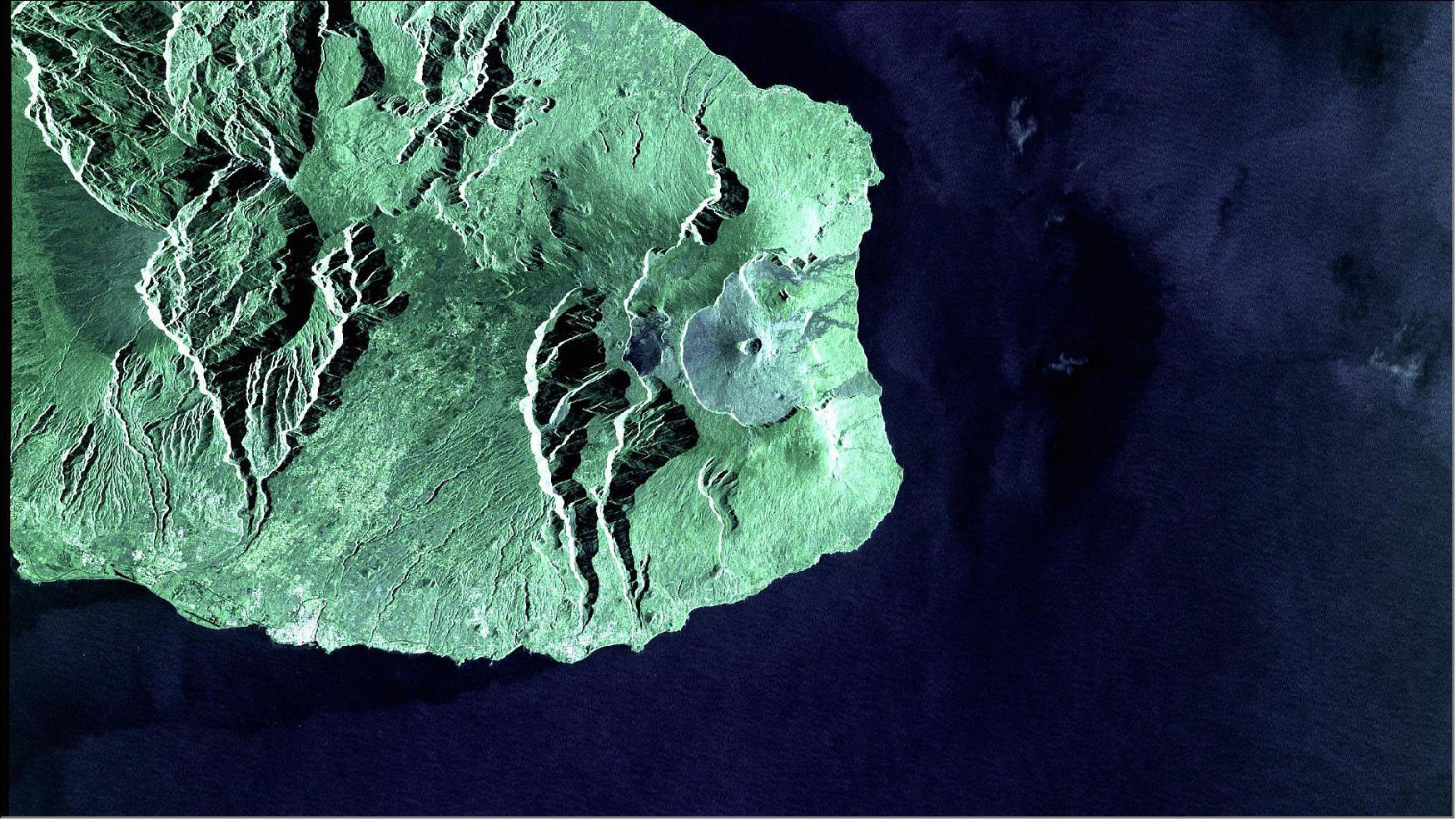
• June 1, 2016: ESA today unveiled the first Sentinel-1 satellite images sent via the European Data Relay System’s world-leading laser technology in high orbit. The two images (Figures 20 and 21) were taken by the radar on the Copernicus Sentinel-1A over La Reunion Island (Indian Ocean) and its coastal area. The first was scanned in a high-resolution mode, the second in a wide-swath mode that provides broad coverage of surrounding waters, and used in particular for maritime surveillance. 51)
- Sentinel-1A in LEO (at 28,000 km/hr) transmitted the images to the EDRS-A node in geostationary orbit via a laser beam at 600 Mbit/s. The laser terminal is capable of working at 1.8 Gbit/s, allowing EDRS to relay up to 50 TB a day. EDRS immediately beamed the data down to Europe. The transfer between the two satellites was fully automated: EDRS connected to Sentinel from more than 35 000 km away, locking on to the laser terminal and holding that link until transmission was completed.
- DLR/GSOC (German Space Operations Center) in Oberpfaffenhofen, Germany, tasked by the MOC (Mission Operating Center) of Airbus Defence and Space in Ottobrunn, received the raw Sentinel-1A data at its station in Weilheim, Germany. They were then passed to the ESA-managed Sentinel-1 ground segment, where they were processed to generate the final products.
- Magali Vaissiere, ESA Director of Telecommunications and Integrated Applications, said at the Berlin Airshow today, “With today’s first link, EDRS is close to becoming operational, providing services to the Copernicus Sentinel Satellites for the European Commission. EDRS is the world’s first laser relay service and features technologies developed by European industry.”
- For Sentinel-1, EDRS adds flexibility, increasing the availability of products to users. It will also allow fast downlink of data acquired outside of Europe, helping services requiring products in real time, as well as in emergency and crisis situations.
- The European Commission’s Copernicus Sentinel satellites are the first users of the EDRS service. ESA is planning the GlobeNet program to extend EDRS by 2020, providing additional security services to satellites, aircraft and drones.

• April 15, 2016: EDRS-A has been in orbit for a month and its testing is going well. The RSS (Redu Space Services) team in Belgium is now pushing it ever-closer to full service by laying the groundwork for it to be ready for its first laser links to the Copernicus Sentinels. Testing began two weeks after the Eutelsat satellite was launched and while it was still travelling towards its final position at 9°E, over Europe. 52)
- The tests are being performed by a pan-European web of ground and control centers managed by the various partners with Redu Space Services of Belgium playing a key role. The RSS team is carrying out most of the EDRS-A payload tests from ESA’s Redu Center in Belgium in coordination with the DLR German Space Operations Center (GSOC) in Oberpfaffenhofen, Germany, and Eutelsat’s Satellite Control Center in Rambouillet, France. Airbus Defence and Space hold the overall responsibility as the EDRS partnership prime.
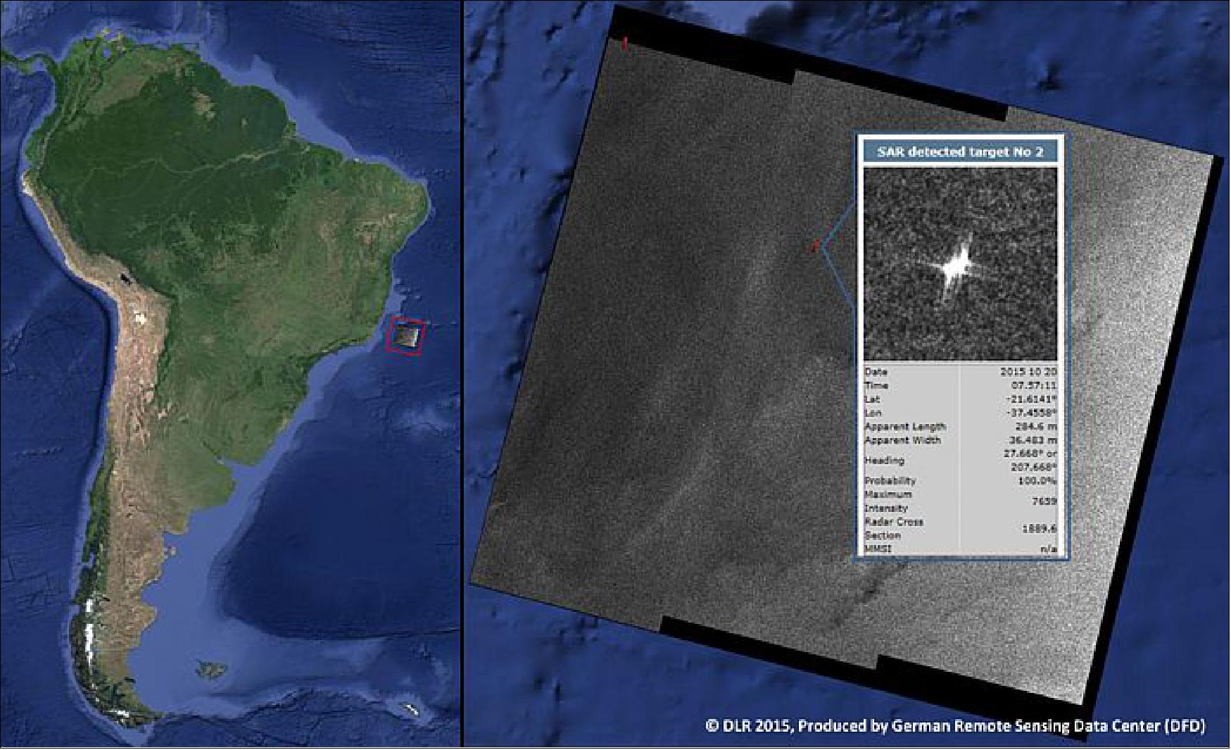
• February 29, 2016: Demonstrating the capabilities of EDRS (European Data Relay System), dubbed “SpaceDataHighway”, and Copernicus, ESA (European Space Agency) together with DLR (German Aerospace Center) and Tesat-Spacecom demonstrated the first quasi-real-time end-to-end delivery of a processed SAR (Synthetic Aperture Radar) image and ship detection information from an area farfrom any ground station within 18 minutes, using laser communication via a data relay. 53) 54)
- The Sentinel-1A SAR data collected over the South Atlantic (off Brazilian coast) have been received, after being relayed via optical intersatellite link to TDP1 (Technology Demonstration Payload No 1), at DLR facilities. By using the DLR ground segment in Oberpfaffenhofen and Neustrelitz, Germany, the raw data have been processed to a Level 1 image within 13 minutes after the data collect. The ship detection information was available after 18 minutes from the collect. This is well within the expectations for such information to be actionable for maritime surveillance.
- Maritime surveillance is benefitting to a major extent from satellites monitoring the Earth's surface with SAR, being capable of detecting ships and oil spills independent of weather and cloud covers. Within the Copernicus program the Sentinel-1 satellites carry a SAR, and thus is of major relevance for maritime surveillance in context of environmental protection, illegal migration, trafficking, piracy, and illegal fishing.
- Information like ship detection reports retrieved from SAR satellite imagery must be fresh to be actionable. This requires an immediate transfer of the imagery to ground, where it is processed, analyzed, and provided to the surveillance expert on duty. To still be considered actionable the information should be available in less than 30 minutes.
- Contributors to the information latency are the ground processing and analysis time, and the data transfer time from the satellite to the ground. The latter can be more than an hour if the satellite has to travel until reaching the next ground station following the image collection over the area of interest. To cut such delays down the use of an intersatellite data relay is an efficient solution.
- One of EDRS’s services is to assist maritime surveillance with near- and quasi-realtime ship detection data. Eighteen minutes from collect to processing is well within the sector’s needs to react to rapidly evolving situations like oil spills, illegal migration and piracy. Without EDRS, the time between the data being collected and the satellite passing over a ground station can be more than an hour.
• January 30, 2016: EDRS-A has reached space aboard its host satellite and is now under way to its final operating position at 9º longitude over Europe, where it will be operated by Eutelsat. 55)
EDRS space segment:
The EDRS will be a constellation of GEO satellites intended to relay user data between LEO satellites, as well as UAVs (Unmanned Aerial Vehicles) in the future, and ground stations. EDRS will allow visibility between GEO and LEO satellites for the larger part of the orbits, offering significantly extended communication periods when otherwise LEO satellites only have a very reduced visibility from any ground station. EDRS is envisaged to significantly improve the stringent timeliness requirements of demanding Earth observation missions (i.e., time critical services).
The EDRS space segment is composed of two elements (Ref. 3):
1) The EDRS-A hosted payload, which contains a Laser Communications Terminal (LCT) and a Ka-band terminal for OISL (Optical Intersatellite Link) and Ka-band ISL, respectively. The EDRS-A payload will be placed as a piggyback payload on-board Eutelsat-9B commercial telecommunication GEO satellite manufactured by Airbus Defense and Space (formerly Astrium Satellites SAS,France). The Eutelsat- 9B satellite, which is based on Astrium’s Eurostar E3000 bus heritage. 56)
Over its 15-year mission lifetime, Eutelsat-9B will operate up to 66 Ku-band transponders connected to a broad European widebeam and four regional beams over European countries. It will increase Eutelsat’s capacity for video services in Europe, providing wide coverage for channels seeking maximum reach into satellite homes and terrestrial headends, as well as regional footprints addressing linguistic markets for digital TV in Italy, Germany, Greece and the Nordic/Baltic regions.
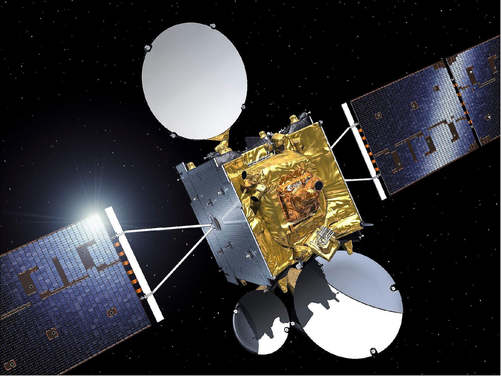
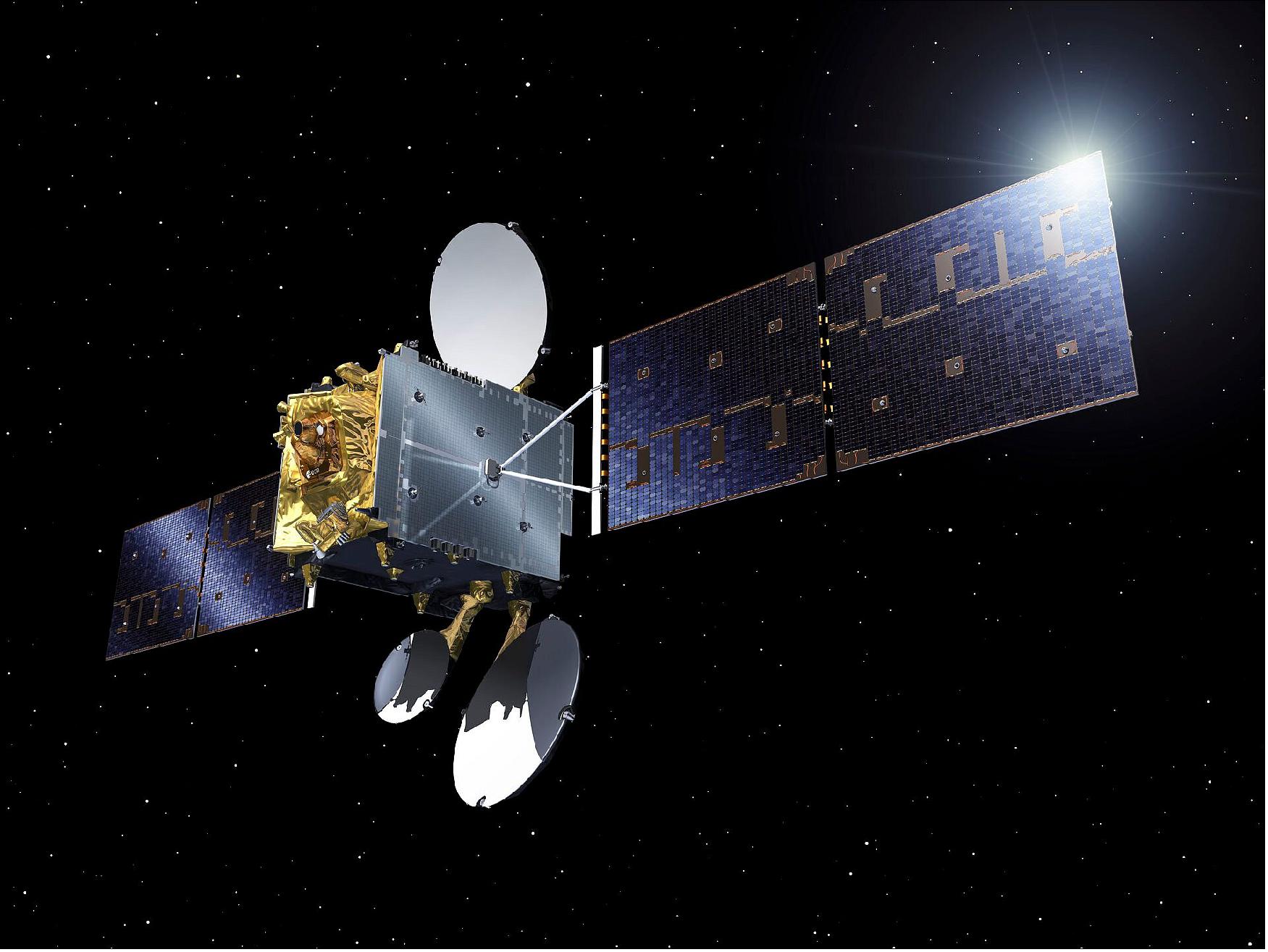
2) The EDRS-C platform (dedicated satellite manufactured by OHB of Bremen, Germany) carrying the EDRS-C payload (which includes an LCT for OISL). The EDRS-C satellite is based on the OHB developed SGEO (Small GEO) platform with an increased payload capability of about 360 kg and 3 kW and a lifetime of 15 years. This node will also host a 3rd party payload called HYLAS-3 built by MDA Corporation (Canada) for Avanti Communications (United Kingdom). The final orbital location is at 31ºE, taking into account the needs from other payloads on board.
The development and manufacturing of both the EDRS-A payload and the dedicated EDRS-C satellite (including the EDRS-C payload) are executed in parallel. EDRS-A and EDRS-C payloads (including the LCTs) are manufactured by Tesat Spacecom (Backnang, Germany; Tesat Spacecom is a subsidiary of Airbus Defence and Space).
The Eutelsat 9B satellite, in addition to Eutelsat’s main payload and the EDRS-A payload, will also host the so-called “ASI Opportunity Payload,” funded by ASI (Italian Space Agency. Furthermore, the EDRS-C Satellite will also embark the so-called HP (Hosted Payload), an opportunity offered by ESA to fill up the spare payload capacity on the EDRS-C platform. The Hylas-3 Ka-band payload has been selected by ESA for embarkation as a HP. The contract between ESA and the commercial satellite operator Avanti Communications (UK), the owner of the Hylas-3 payload, has been signed in July 2012. The Hylas-3 payload is procured by Avanti Communications, and the integration and test activities with the EDRS-C platform will be conducted jointly with OHB. 57)
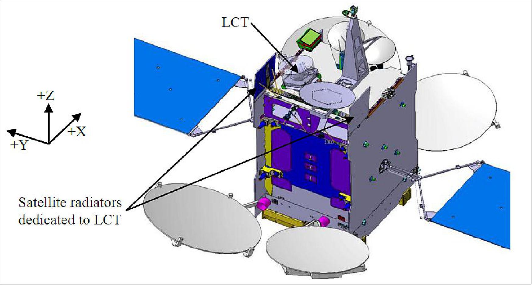
Eutelsat 9B Layout: The LCT is accommodated on the hosting satellite Earth deck to allow pointing towards the Earth direction within the operational FOV, without any obstruction. The Eutelsat 9B satellite configuration is shown in Figure 24 with focus on the Earth deck where the LCT is accommodated (Ref. 56).
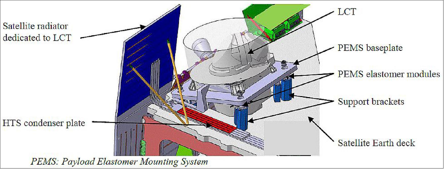
The LCT FUS (Frame Unit System) baseplate is tilted by 15º with respect to the Earth deck plane to ensure the CPA (Coarse Pointing Assembly) azimuth rotation axis is far enough (more than 3º) from the edge of the operational FOV. Figure 25 shows the tilted FUS baseplate and HTS (Heat Transport System) condenser plate interface to the satellite. The condenser plate is connected to dedicated radiators through heat pipe networks.
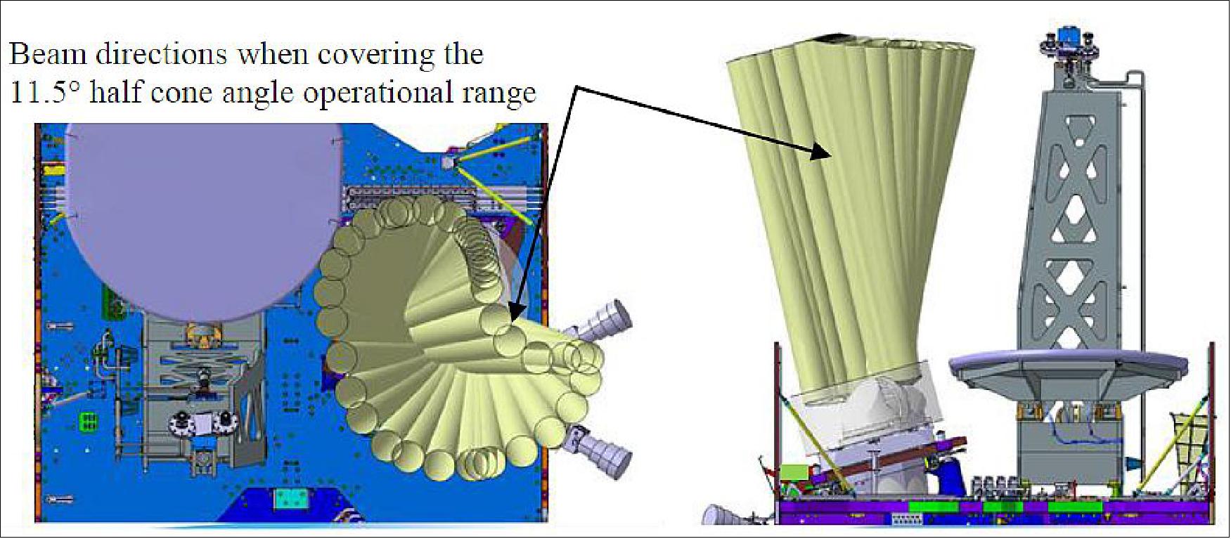
The LCT accommodation guarantees its FOV is free of any obstruction (as shown in Figure 26). The “bean shape” of the actual FOV is due to the fact that the CPA aperture is offset with respect to the azimuth rotation axis and to the specific coupling between azimuth and elevation angles when pointing in a required direction.
Dedicated shielding screens and MLI blankets are implemented between the LCT FUS baseplate and the satellite top floor covering the HTS tubing and condenser plate to provide protection of the LCT against the space environment (radiation and micro-meteorites).
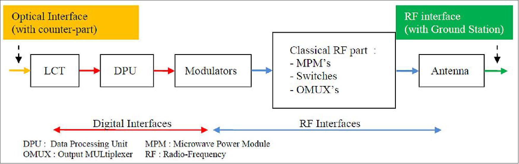
EDRS-A payload: The part of the EDRS-A payload related to the OISL is sketched in Figure 8. The data received by the LCT are transferred to modulators through the DPU (Data Processing Unit). Modulators generate the corresponding RF (Radio Frequency) signal which is amplified and transferred to the ground via the dedicated antenna.
ESA will act as a major customer for Airbus DS (former Astrium) paying for relay services of data from the Sentinel satellites. However the system is designed such that more customers can be integrated.
Hybrid payload for EDRS: 58)
The motivation for EDRS was to overcome the drawbacks of classical LEO data transmission capabilities to ground, i.e. limited transferred data volume and data latency, by using high speed OISL (Optical Intersatellite Links) between LEO and GEO relay satellite and multi channel RF downlinks in Ka-band for the GEO to ground links. The motivation for to realize the payload system, is that Tesat Spacecom as one of the major satellite communication equipment and subsystem designer and manufacturer has all competence and heritage to realize such a system for commercial application.
Seen from a geostationary relay satellite, the visibility of a LEO satellite increases at least by a factor of 4 to approximately 45 minutes. The LCTs (Laser Communication Terminals) operating on both, LEO and GEO satellites exchange data with up to 1800 Mbit/s in Advanced Mode, hence an increase by an additional factor of 3.5 compared to conventional X-band data downlinks. This means an increase by a factor 14 of the data volume that can be dumped down to Earth per LEO orbit! - The first users of the EDRS GEO payloads are the Sentinel-1 and -2 satellites of ESA. Those carry LCTs and operate in a legacy Sentinel Mode, with data transmission at 600 Mbit/s.
A Ka-band ISL is present in addition to the OISL on EDRS-A only. This RF link follows the trajectory by means of a steerable reflector antenna. It constitutes mainly a transparent repeater with approximately 300 Mbit/s data rate.
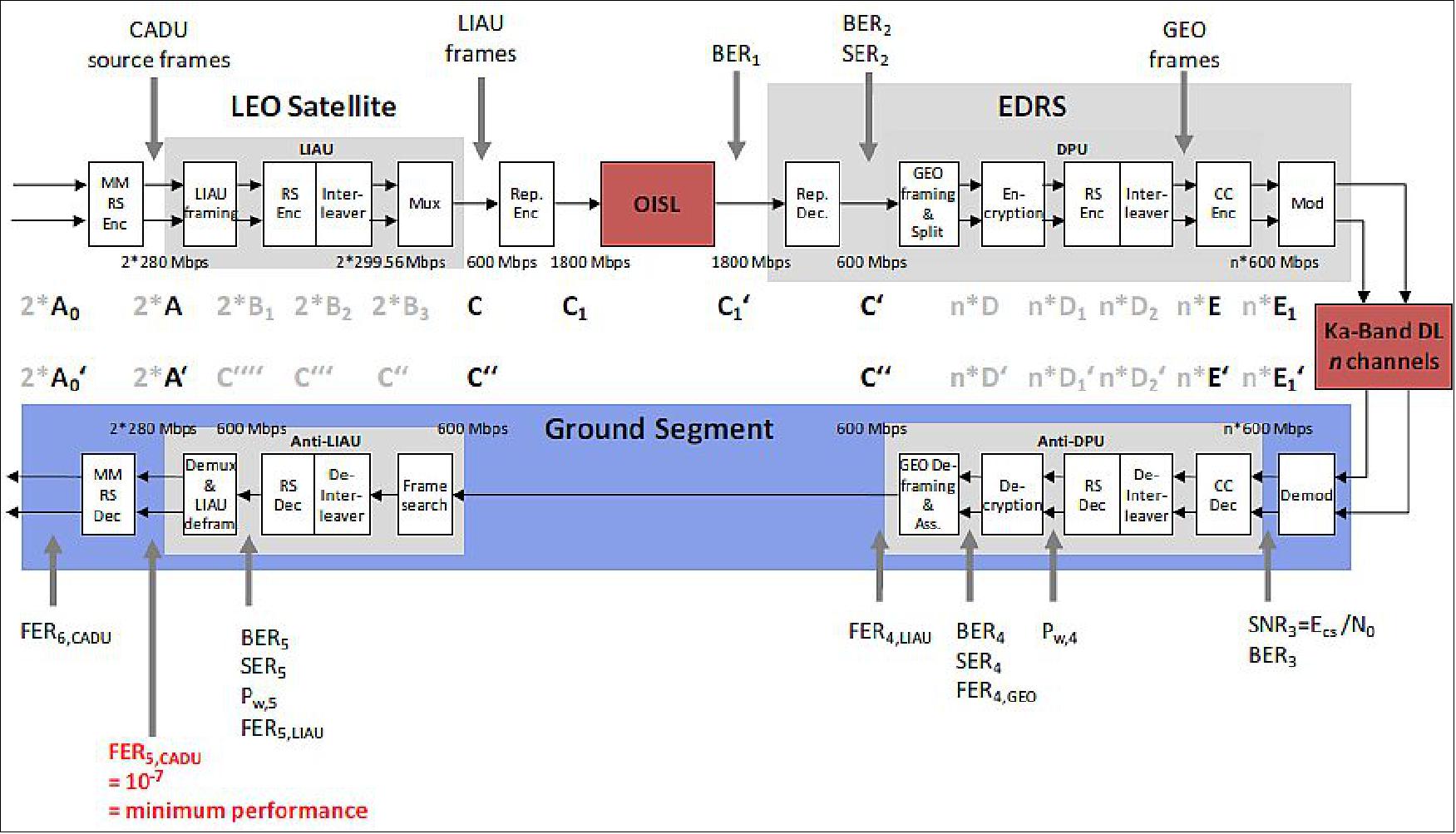
The design of the EDRS payloads is driven by the overall EDRS system design, shown in Figure 31 in terms of the data flow from data source to data sink. The EDRS system includes the Sentinel-1 and Sentinel-2 LEO satellites, each of them equipped with a LCT. The interface from the LEO’s mass memory, which stores the acquired sensor data of the LEO instruments, is connected to the LCT via LIAU (LCT Interface Adaption Unit (LIAU).
The main purpose of the LIAU is threefold, first it combines the two mass memory 8-bit wide input data streams containing CADU frames (each with approx. 280 Mbit/s) into one 16-bit bit wide output data stream. Second, it performs initial data framing (into so-called LIAU frames) and RS (255, 239) encoding. And third, it performs a data rate adaptation by stuffing idle data frames in order to achieve exactly 600 Mbit/s.
The repetition line encoding inside the LCT improves the optical channel performance further and adapts to the LCT net bit rate of 1800 Mbit/s. After reception by the GEO LCT, the received data is further channel-coded in the DPU.
A key contributor to errors introduced on the OISL data transmission is the respective satellites µ-vibration spectrum, originating from various sources like reaction wheels and solar array drive mechanisms. It has been found that the SNR (Signal-to-Noise Ratio) and the error statistics on the OISL are only slowly time-variant compared to the LIAU frame duration. Moreover, the SNR variations are rather small and limited to about 1 dB. Extensive simulations have been performed by Tesat to validate the efficiency of the employed channel codings. Those concluded, that the overall FER (Frame Error Rate) of 10-7 at the data sink on ground can be well achieved.
Service type | Data flow | Data rate | Service available on GEO-Node |
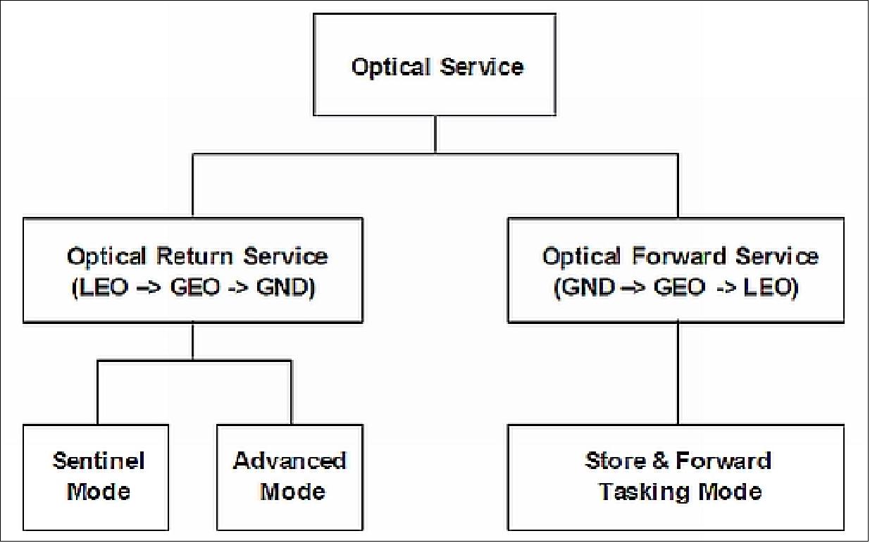
Optical ISL return service | LEO→GEO→Ground | 600 Mbit/s or 1.8 Gbit/s | EDRS-A, EDRS-C |
Optical ISL forward service | Ground→GEO→LEO | 500 bit/s | EDRS-A |
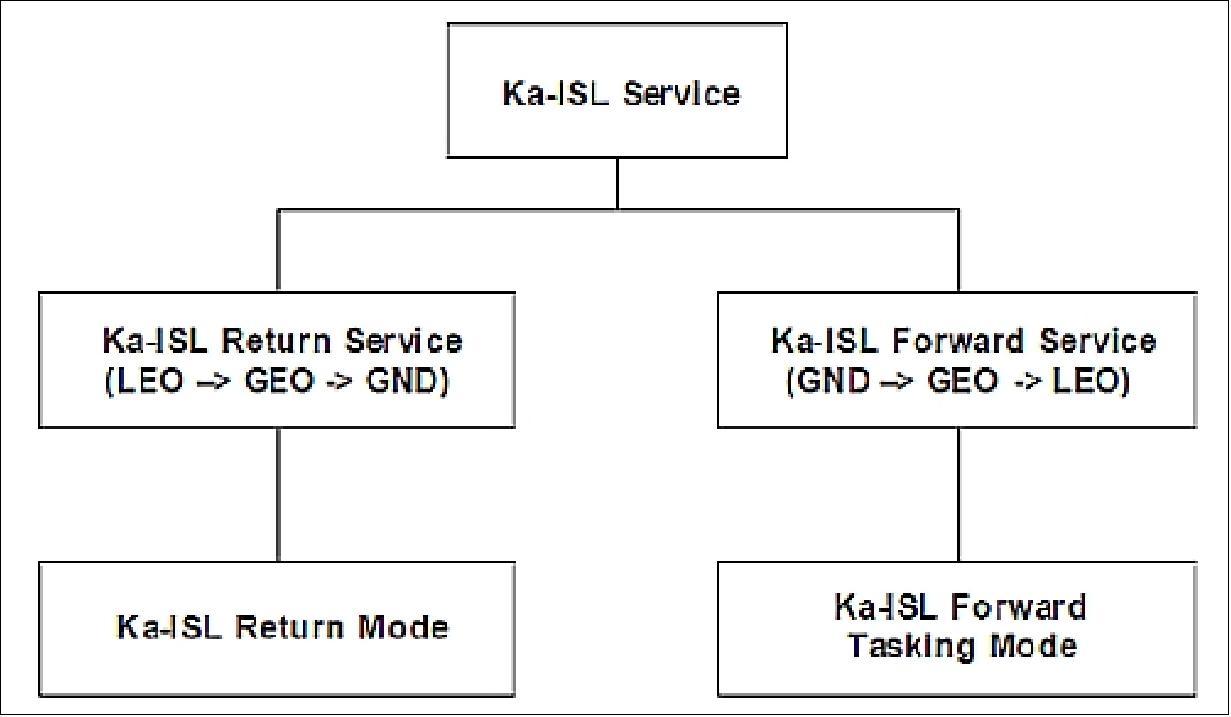
Ka-ISL return service | LEO→GEO→Ground | 300 Mbit/s | EDRS-A |
Ka-ISL forward service | Ground→GEO→LEO | 1 Mbit/s | EDRS-A |
One of the main functions of the DPU are to split the 16-bit wide 1800 Mbit/s data stream from the LCT into two (Sentinel Mode) or four (Advanced Mode) data streams that will be picked up by the respective modulators later applied to the information rate of 300 Mbit/s. As for the Sentinel mode 2, active channels are used, these sum up to 600 Mbit/s useful data rate (Table 2).
Parameter | Sentinel Mode | Advanced Mode |
Operational modes (selectable via TC) | X-band | X-band |
Total OISL data rate | 600 Mbit/s | 1800 Mbit/s |
RF D/L channels | 2 | 4 |
Information data rate per channel | 300 Mbit/s | 450 Mbit/s |
Encoded data rate per RF channel | 600 Mbit/s | 600 Mbit/s |
Downlink channel coding | convolutional coding, Reed-Solomon (255,239) | convolutional coding, Reed-Solomon (255,239) |
Convolutional code rate | 2/3 | 5/6 |
Encryption | AES (Advanced Encryption Standard) | N/A |
Polarization | LHCP, RHCP | LHCP, RHCP |
Downlink frequency | 26 GHz | |
Channel bandwidth per polarization | 450 MHz each | 450 MHz each |
Total RF bandwidth | 900 MHz | 1800 MHz |
EIRP per channel | > 51 dBW | |
Power consumption (including LCT) | < 800 W | |
Mass | EDRS-A 170 kg, EDRS-C 130 kg (including LCT, antennas) | |
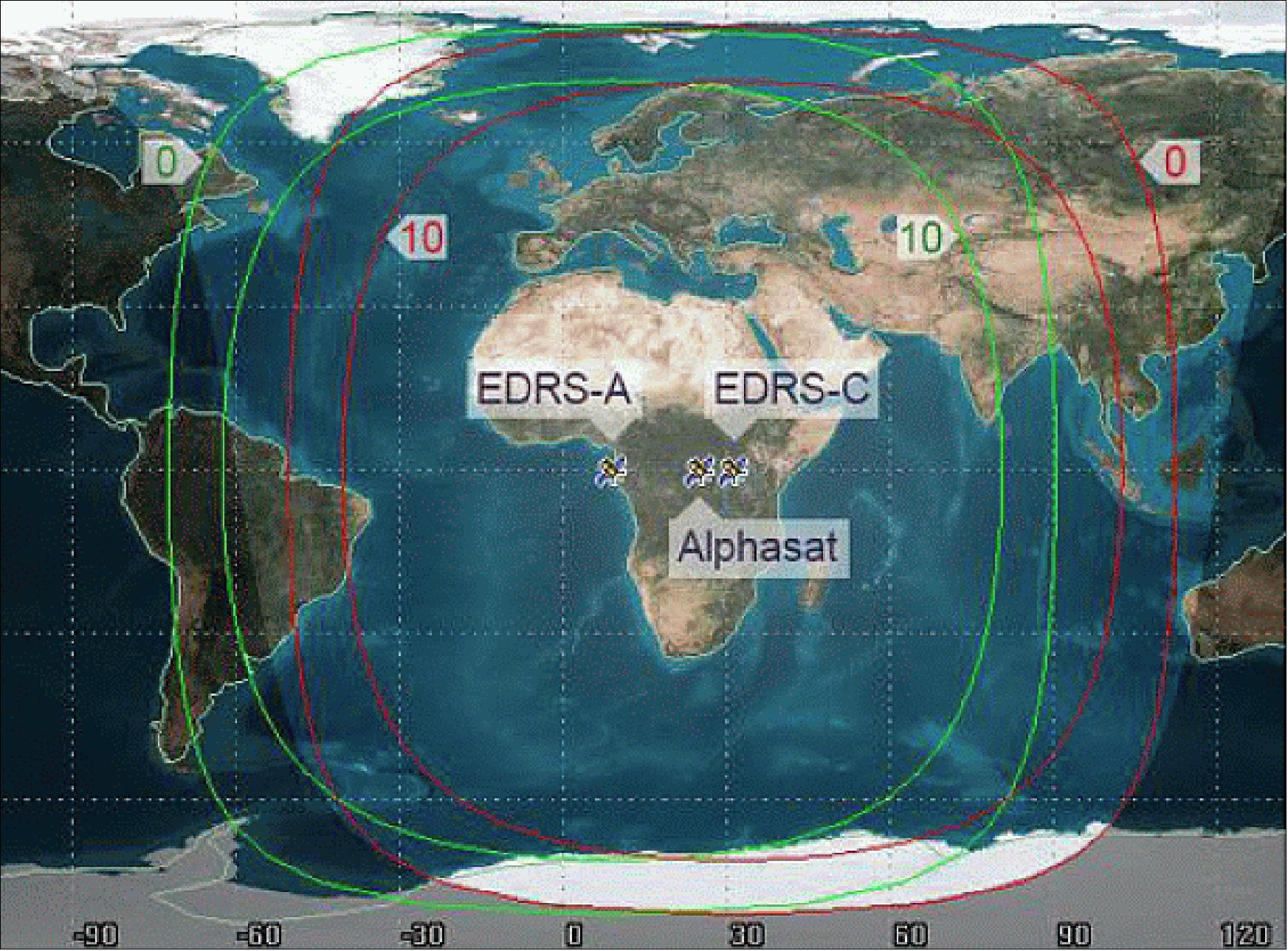
Legend to Figure 33: The orbital position of the Alphasat satellite is also shown. The Antarctic coastline east and west of +20º longitude sees these GEO-satellites at more than 10º elevation.
LCT (Laser Communication Terminal):
Compared to typical RF communication systems laser communication terminals (LCT) offer the advantage of higher data rate and larger link distance at lower size, weight and power. The major factor is the four orders of magnitude shorter carrier wavelength translating into higher antenna gain. As additional benefits, laser communication links are free of interference problems, they provide secure transmission and the user is not limited by ITU regulations. Of the available optical technologies homodyne BPSK (Binary Phase Shift Keying) is superior due to the merits of: 60) 61) 62)
• Spatial filtering by the homodyne detection cone (the narrowest possible for a given aperture)
• Frequency filtering by phase locking loop (far more selective than available optical coatings)
• Leveraging the signal amplitude (superposition with orders of magnitude larger than the local oscillator amplitude).
The objective of the LCT is to operate a duplex communication link for binary digital data between two satellites or a ground station via a single optical carrier at 1.064 µm wavelength. The demonstration LCTs, accommodated on the TerraSAR-X (launch June 15, 2007) and NFIRE (Near Field Infrared Experiment) spacecraft of DoD (launch April 24, 2007), are considered to be verified on orbit throughout multi-year routine operations. More than 100 ISLs (Intersatellite Links) with bidirectional communication have been established so far. The first 2nd generation LCT , with the TDP1 (Technology Demonstration Package No 1), will be flown on Alphasat-1 / Inmarsat I-XL, a GEO spacecraft scheduled for launch in Q2 2013 (positioned at longitude 25º E).
The EDRS OISLs are based on 2nd generation LCTs (Laser Communication Terminals) which are developed and qualified by Tesat Spacecom (Germany) under DLR German national funding (Ref. 56) . These LCTs feature a significantly increased data transmission rate compared to SILEX technology, and at the same time reduced mass and size (Ref. 3). 63) 64) 65)
Parameter | SILEX Optical Terminal | 1st generation Tesat LCT | 2nd generation Tesat LCT |
Wavelength | 810 - 850 nm | 1064 nm | 1064 nm |
Modulation type | OOK-NRZ / 2-PPM | BPSK | BPSK |
Detection scheme | Direct detection | Coherent homodyne | Coherent homodyne |
User data rate | 0.05 Gbit/s | 5.625 Gbit/s | 1.8 Gbit/s (user data) |
Range of optical link | up to 45000 km | > 5100 km | up to 45000 km |
BEP (Bit Error Probability) | < 10-6 | < 10-11 | < 10-8 |
Transmit power (average) | 0.06 W | 0.7 W | 2.2 W |
Telescope diameter | 250 mm | 125 mm | 135 mm |
Mass | 157 kg | 35 kg | 56 kg |
Power consumption (average) | 150 W | 120 W | 185 W |
Instrument envelope | N/A | 0.5 m x 0.5 m x 0.6 m | 0.6 m x 0.6 m x 0.7 m |
Applications | LEO-GEO OISLs | LEO-LEO OISLs | LEO-LEO OISLs |
Missions with optical link | ARTEMIS, SPOT-4, OICETS | TerraSAR-X, N-FIRE, TanDEM-X | Alphasat, EDRS, Sentinel series, etc. |
The EDRS LCTs will benefit from the space heritage attained in the following in-orbit demonstrations led by DLR (German Aerospace Center):
• The in-orbit verification of the 1st generation Tesat LCT as part of the LEO-LEO OISL between TerraSAR-X (German LEO satellite) and NFIRE (US LEO satellite), which took place in 2008, at a data rate of 5.6 Gbit/s over link distances of about 5000 km. It demonstrated the feasibility of beaconless spatial acquisition and the communications performance of the homodyne BPSK detection scheme (data stream of 5.625 Gbit/s with a BEP <10-9).
• The in-orbit validation, in cooperation with ESA and the Swiss Space Office, of the 2nd generation Tesat LCT as part of the LEO-GEO OISL between the GEO LCT embarked on ESA’s Alphasat satellite, (Figure 34) and the LEO LCTs on board Sentinel-1A/-2A satellites. It will demonstrate a LEO-GEO bidirectional link. Furthermore, it will perform end-to-end preoperational experiments between Sentinels-1A/-2A satellites and Alphasat (i.e., EDRS precursor) at 600 Mbit/s of user data rate. The Alphasat spacecraft was launched on July 25, 2013, whereas the launch of Sentinel-1A and Sentinel-2A satellites is expected in 2014 and 2015, respectively.
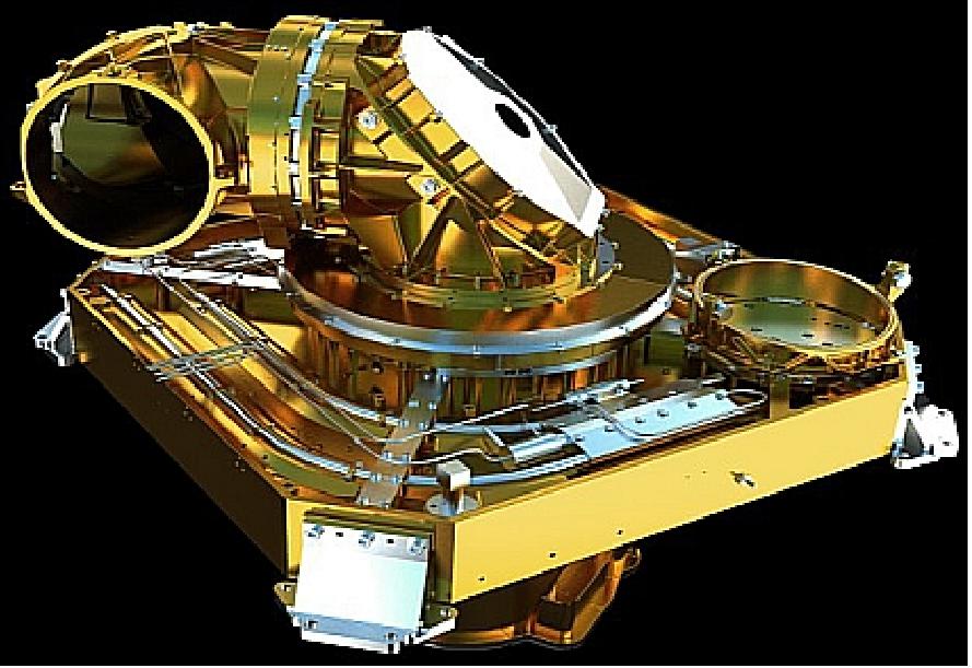
LCT instrument: The LCT itself consists of all subunits necessary to perform an optical data relay link, including data electronics for the transmit and receive paths, laser and fiber amplifiers and corresponding driver circuits as well as a computer that manages the operation, monitoring and control of the subunits. The LCT also contains a digital interface with the satellite main data bus, the mechanisms (coarse and fine pointer) and beam expander optics. The satellite bus voltage is converted into stabilized outputs for the internal electronics using a dedicated subunit.
All subunits are implemented on a single FUS (Frame Unit System) as shown in Figure 35. This unit also embeds part of the HTS (Heat Transport System) collecting power to be dissipated externally to the LCT through a dedicated condenser plate which is the main thermal interface of the LCT with the hosting satellite.
The CPA (Coarse Pointing Assembly) implements two articulations (called azimuth and elevation) to allow the optical beam to be pointed towards the target during a link: the azimuth rotation axis is perpendicular to the FUS baseplate and the elevation rotation axis is perpendicular to the azimuth rotation axis. The hemispherical CPA is locked in a park position for launch.
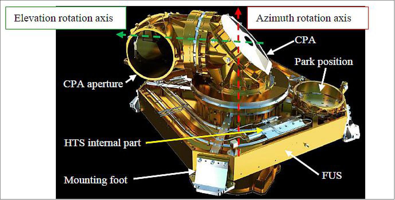
The LCT block diagram is shown in Figure 36. Major changes are: For the 2nd generation LCT, an off-axis telescope is chosen, the optical power amplifier is changed to a 5 W device, the receiver is optimized for a user data rate of 1.8Gbit/s. For GEO applications, the electronics were redesigned to operate the adapted devices and to match with the GEO radiation environment for 15 years of continuous service. The thermal system is improved, the mechanics scaled for the bigger units.
LCT generic design/qualification approach: The LCTs are built such, that the LCTs for GEO and LEO application are same for its units design and their qualification. The GEO and LEO LCTs have identical optical space interfaces with same performance.
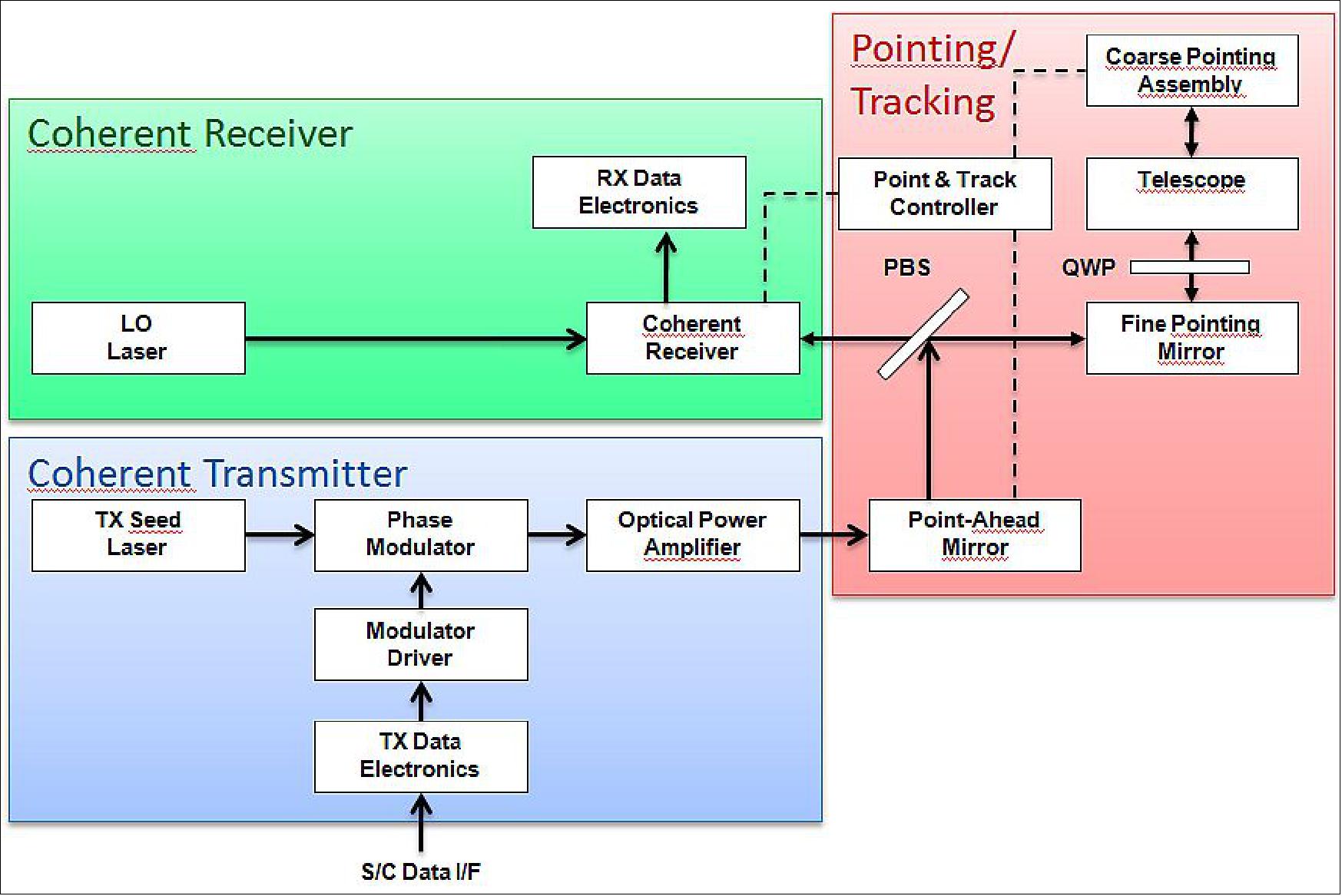
The optical data and laser paths are shown in Figure 36. The transmitted optical beam is generated by the coherent transmitter and correctly pointed towards the counter-part after deviation by point-ahead, fine pointing and CPA mirrors. The incoming beam is deviated by the CPA mirrors, then the fine pointing mirror before reaching the coherent receiver.
The HTS consists of two variable conductance loop heat pipes that enable a temperature control of the FUS under varying environmental and power conditions. The interface temperature of the HTS condenser plate (Figure 37) is maintained within the operational range (between -10ºC and +15ºC).
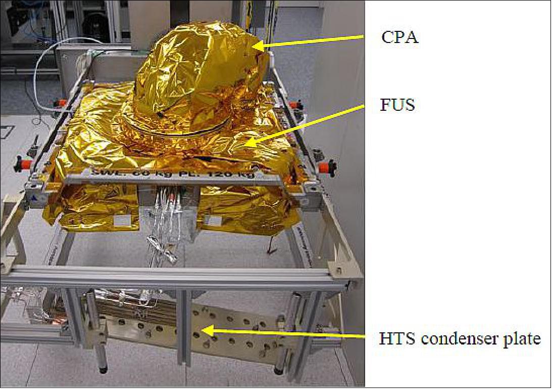
The LCT one-unit design consists of a central rectangular base structure, a coarse pointer (gimbal) mounted on space side and the optics unit reaching through this structure on the S/C side. The frame unit structure houses the entire laser communication terminals electronics and active optics.
The optics unit comprises the receive/transmit optics, fine steering mechanisms and the receiver. A single telescope as optical antenna serves as common transmit and receive path. The coarse pointer is designed for hemispherical tracking of the counter terminal. In park position, the optics are protected during non-operational modes against contamination; a launch lock secures the coarse pointer during launch.
Together with Renishaw (UK), Tesat has successfully developed and tested a space qualified optical encoder. While it was tailored to the operation in a LCT under harsh environmental conditions outside the spacecraft in GEO, it can be used as well for many other applications in high precision, long life space instruments. 66)
Resolution | < 0.5 µrad |
Position jitter | < 1 µrad rms over 1º range and f < 100 Hz (interpolation error < 0.5 µrad rms) |
Velocity | > 25º/s |
Electric power | < 3 W |
Instrument mass | < 300 g without scale |
Temperature range | -30ºC ≤ T ≤+70ºC (operation and storage nominal) |
Vibration | Design 150 g static, random 24.7 g rms |
Radiation environment | GEO and LEO orbit, 15 years |
EMC (Electromagnetic Compatibility) | Radiated according to MIL-STD- 461/462, emission 10 dB below MIL-STD-461/462 E |
Lifetime | 15 years in GEO orbit |
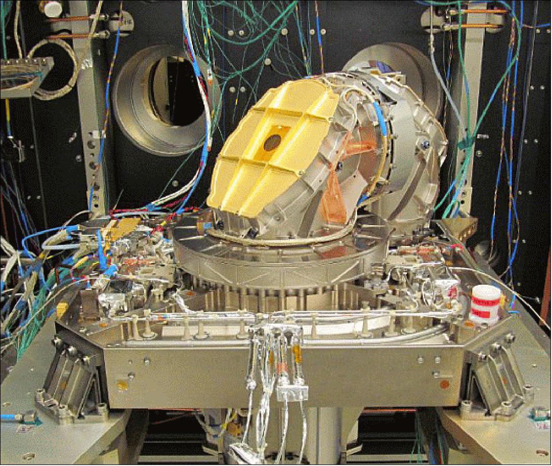
Main LCT Hosting Requirements:
Most of the LCT hosting requirements are similar to interface requirements of other equipment installed on the hosting platform (e.g. electrical interface, mechanical interface, data bus interface) and are handled following Eurostar E3000 standard processes. Special care was paid to a few requirements that are specific to the LCT. They are similar to requirements for hosting other optical instruments which require high pointing stability.
The LCT power dissipation depends on the mode in which it is running. Its maximum power dissipation is similar to TWT (Travelling Wave Tubes) used on telecommunications satellites. A specific feature of the LCT is that it requires an interface temperature at HTS condenser level lower than 15ºC.
Pointing towards a target and following its trajectory is performed by combining CPA rotations around azimuth and elevation axes. By design, this two-axes mechanism is such that for a given target speed, the closer the pointing direction is to the azimuth rotation axis, the faster the azimuth rotation speed will be. The azimuth rotation axis is tilted with respect to the nadir direction to be outside the operational FOV (Field of View), thereby limiting the maximum azimuth rotation speed. The trajectories of LEO satellites for altitudes up to 2000 km, seen from a geostationary position, are all within a cone of 11.5º half cone angle. The geometrical accommodation also needs to ensure a FOV free from obstructions when in operating conditions to allow performing a link with a target that can have an orbit altitude up to 2000 km, as shown in Figure 39.
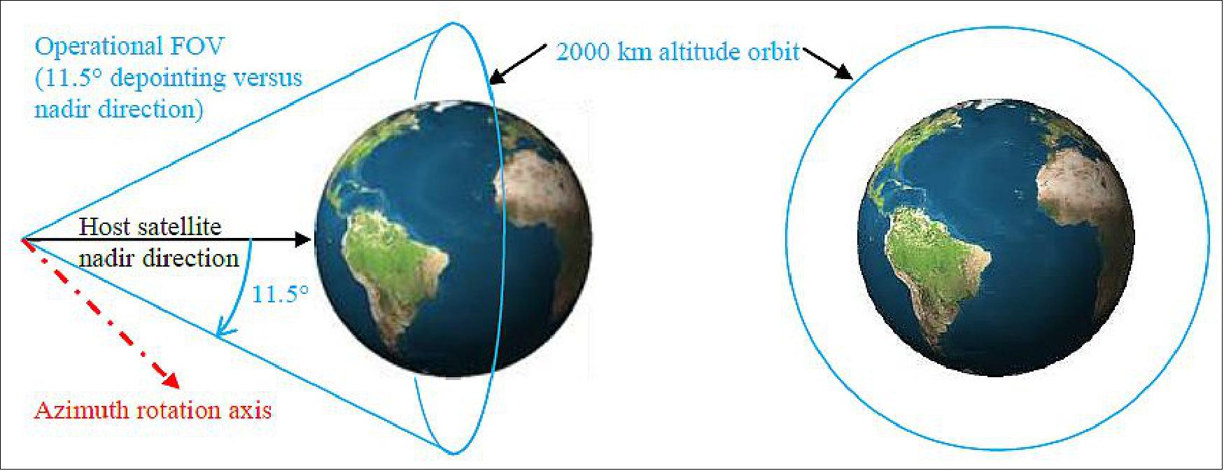
The link acquisition process is performed in open loop and requires both high pointing accuracy of the beam towards the counter-part as well as high pointing stability of the beam:
• In order to establish a link, both terminals have to be pointed accurately towards each other. The pointing direction of each terminal is computed taking into account the orbit position and velocity of the counter-part, the orbit position and velocity of the hosting satellite and the attitude of the hosting satellite. The maximum pointing error that remains during this open loop pointing phase defines the Uncertainty Cone (UC). This UC is larger than the beam divergence, but must be kept lower than the LCT acquisition sensor FOV (2500 µrad half cone angle). It is also important to note that the acquisition process is such that the smaller the UC is, the shorter the link acquisition duration will be. — The positions and velocities of the satellites hosting the two terminals during the link are predicted using orbit models computed by the operational ground segments. The relevant information is transferred to the corresponding LCTs in advance of the link by uploading a set of five telecommand blocks.
• One key step of the acquisition process is the scanning of the UC with the beam to ensure the counterpart will be illuminated at least once during one complete scanning. The detection of the incoming beam once per scanning allows the counterpart to reduce its own pointing error. Pointing stability of the hosting satellite is consequently a key asset during this phase to ensure a good coverage of the whole UC when scanning the narrow beam.
• Start of the acquisition process needs to be time-synchronized between the two terminals which will go through a scanning / repointing process until the beam of each terminal is repointed and tracked accurately on its TS (Tracking Sensor).
Regarding the hosting satellite, the LCT acquisition process therefore requires:
• Accurate absolute time reference: the start of the link acquisition process has to be synchronized with accuracy better than 0.5 seconds between the 2 LCT’s engaged in the link.
• Accurate orbital position knowledge for the hosting satellite: conventional orbit determination methods using ground station ranging are sufficient for the hosting geostationary satellite. The orbital position of the target is propagated autonomously on-board the LCT itself using a dedicated model.
• Accurate pointing knowledge: the satellite pointing performance is one of the contributors to the UC. The standard pointing performance of a telecommunications satellite results from several errors (e.g. initial alignment and stability between attitude sensors and payload, attitude control performance, thermoelastic distortions). The maximum pointing error is in the range of 1200-1500 µrad, but the contribution to the LCT Line Of Sight (LOS) pointing error is usually not accurate enough with respect to the LCT requirements (an overall pointing error of 1500 µrad is targeted to ensure a short enough link acquisition duration). The contribution of the satellite can be improved by using the pointing knowledge using the AOCS (Attitude and Orbit Control System) sensors instead of relying on the pointing performance itself.
• Stable pointing: the required stability of the LCT LOS is far more demanding than the standard performance of a telecommunications satellite. The LCT requires stability in the order of magnitude of 1 µrad peak-to-peak for frequencies greater than 100 Hz, which is 10 to 100 times more stringent than what is achieved in the worst case on standard satellite platforms.
The LCT also needs to be protected against the space environment (radiation and micro-meteorites mainly).
EDRS ground segment:
In addition to the space segment, EDRS will develop the necessary ground segment infrastructure, consisting of (Ref. 3):
• EDRS SCC (Satellite Control Center) facilities: The dedicated EDRS SCC is linked to the EDRS-C spacecraft Operator (i.e., DLR in Oberpfaffenhofen), while for the EDRS-A payload this is a PCC (Payload Control Center) operated by DLR in conjunction with the Eutelsat operated SCC for the 9B satellite.
• EDRS MOC (Mission Operations Center) and the Back-up Mission Operations Center (B-MOC), which are the interface to the users for the planning of the EDRS services requests. The primary MOC will be in Ottobrunn (Germany), while the backup MOC will be installed at Redu Space Services (Belgium). The MOC function is provided by Astrium Services.
• EDRS DGS (Data Ground Stations), enabling reception of user data on ground. Two EDRS DGS shall be operational to provide service after completion of the EDRS-A LEOP (Launch Early Orbit Phase) operations and in-orbit commissioning.
• FLGS (Feeder Link Ground Station) and the B-FLGS (Backup -Feeder Link Ground Station), enabling user data reception as well as providing EDRS-C TM/TC capability. The FLGS and the B-FLGS shall be operational in line with the deployment of the EDRS-C satellite.
In June 2012, Astrium Services signed a contract with DLR (German Aerospace Center) to implement and operate major parts of the ground network. The agreement covers the design, implementation, delivery and operation of four ground stations: two DGS for the EDRS-A satellite in Weilheim (Germany) and in Harwell (United Kingdom), respectively, and the FLGS / B-FLGS for EDRS-C in Weilheim (Germany), and in Redu (Belgium). As part of the agreement, DLR will also implement and operate the DPCC (Devolved Payload Control Center) for EDRS-A and the SCC (Satellite Control Center) for EDRS-C in Oberpfaffenhofen (Germany). Major parts of the Ground Segment have been co-funded by DLR and the government of Bavaria. 67)
The space and ground segment for the EDRS user are intrinsically part of the end-to-end system, including space-to-space, space-to-ground as well as the ground-to-ground interfaces. A joint Copernicus/EDRS System team has been established in support to the definition and implementation of all aspects of the end-to-end link involving the Sentinels. This includes the definition of key performance indicators, applicable to a SLA (Service Level Agreement) between Copernicus and Astrium Services. Up to four Sentinels satellites are currently planned to be served simultaneously, with an average of 10 minutes of communication per orbit each. The current draft SLA expects a start of the service by 2015, extendable in phases until about 2030.
The EDRS concept of operation can be summarized as follows: Communication link sessions are planned and coordinated between the EDRS MOC and the user’s MOC, making use of the visibility windows available between EDRS and the user satellites. The EDRS and the user’s space infrastructure will be configured according to each link session parameters. User data will be transmitted from LEO user satellites to either of the EDRS payloads (i.e., EDRS-A, EDRS-C) and relayed to the DGS and/or FLGS/B-FLGS on the ground, from where it will be made available through terrestrial network to the users’ sites (Figure 28). The users can also operate their own user ground stations to receive directly the user data.
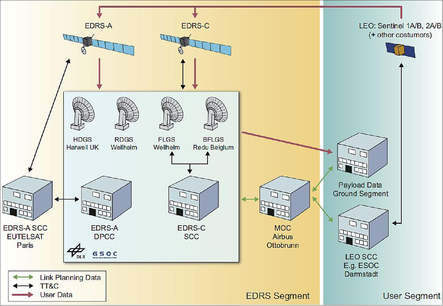
The central part of the EDRS ground segment, shown in Figure 40, is the MOC (Mission Operations Center) established by Airbus Defence and Space. It interfaces with all other components and coordinates the overall mission. On the one hand, it receives the link orders from the different users. It schedules the mission timeline for both EDRS satellites taken all known constraints into account and sends requests for the scheduled links to the DPCC (Devolved Payload Control Center), operating the EDRS-A payload, and the SCC (Spacecraft Control Center), operating the EDRS-C satellite. It also coordinates with four ground stations based at Harwell, Weilheim, and Redu which receive the user data from both EDRS satellites and deliver the data to the users. 68)
DPCC (Devolved Payload Control Center)
The DPCC is responsible for operating the EDRS-A hosted payload. A file-based interface with Eutelsat's SCC, which is operating the Eutelsat-9B satellite, is used for commanding. The telecommands (TC) of typically one flight operations procedure (FOP) are combined into one TC set file, transferred to the SCC in Paris, and released within Eutelsat's commanding system. For monitoring, two separated telemetry streams are received within the DPCC. One is forwarded by the Eutelsat SCC including all satellite telemetry, and one is received at an EDRS dedicated antenna containing only LCT related data.
The MOC is connected to the DPCC via a second file-based interface. The following request types are defined to be delivered by the MOC:
1) Payload link configuration request: The request type for each link execution either by the LCT or the Ka-band inter satellite antenna. It contains information of the link direction (EDRS to LEO, LEO to EDRS, or bidirectional), link speed, and LCT configuration parameters. It also contains coefficients of the LEO satellite's trajectory in the case of an LCT link, or vector data for the pointing direction of the Ka-band antenna.
2) Payload routine configuration request: A generic request type triggering the automatic execution of a flight operations procedure. The request contains the ID of the FOP, the necessary parameters for the FOP, and an execution time. Only a small number of FOP are possible to be requested for automated execution.
3) Payload basic configuration request: A generic request for the manual execution of a FOP. Similar to the routine request it contains the ID of the requested FOP, its parameters, and execution time. Contrary to a routine request this FOP is executed manually by the DPCC's flight operations team. Only a small quantity of requests of this type are expected and therefore no automatic mechanism is established.
4) Forward tasking data request: The LCT link service provides a mechanism to forward data from the EDRS GEO satellite to the target LEO satellite. These binary data are delivered to the DPCC via forward tasking data request and uploaded into the DPU (Data Processing Unit) on-board EDRS.
5) Payload configuration deletion request: All request types above can be deleted by this request type. In the case that the DPCC's internal processing is ongoing the process is stopped internally. Otherwise, if the request is already processed into TC sets forwarded to the Eutelsat SCC, a FOP to delete the commands from the on-board time-tag TC buffer is generated and executed.
The DPCC is located inside the multi-mission environment of DLR/GSOC (German Space Operation Center) in Oberpfaffenhofen. The very concept of multimission is based on the sharing of existing infrastructure (buildings, network, and software) with other missions. Within this environment a layered architecture of several components providing the EDRS service has been created. 69) A LMS (Link Management System) is processing the automatic requests received from the MOC. It interacts with a flight dynamics system and the Automator. The latter is the central component executing the automatized flight operations procedures. All components are reporting their current status to a common monitoring tool.
Due to the commercial nature of the program, highly ambitious performance requirements have been defined and need to be met by the DPCC: the service level agreement foresees continuous payload utilization, up to 200 links per day and communication channel, over the expected lifetime of 15 years, with a targeted service availability of at least 99.6% over 60 days and an order reaction time well below one hour; a task that can hardly be handled in a manual or semi-automated operations concept.
The EDRS payload is therefore controlled using a fully-automated operations engine which complements GSOC's core MCS (Monitoring and Control System), an enhanced derivative of ESA's SCOS-2000 v3.1 (Satellite Control and Operation System-2000, Version 3.1). The automation engine is designed to supervise the complete cycle of telecommand uplink and execution, as well as reaction monitoring of telemetry. Updates to the onboard mission timeline are scheduled and uplinked autonomously, triggered either by spacecraft events or high-level external link requests. Telemetry analysis and key performance indicators are provided in quasi real-time to the MOC (Mission Operations Center).
With EDRS-C being hosted on a very different platform than EDRS-A, the DPCC ground segment was designed to be independent of the particular spacecraft platform. This is realized via a layered system architecture centered around the core MCS, with layer 1 consisting of the commanding front-end and automation engine while layer 2 comprises the LMS (Link Management System) and interface to the MOC. This layered architecture allows for a seamless phase-in of EDRS-C, with no software changes required for layer 2 and only minor upgrades to components of layer 1. Differences in the platform will be masked through the versatility of the core MCS. 70)
The DPCC routine activities fall into two categories: nominal activities related to the provision of the link service, based on high-level requests from the Mission Operations Center. Secondly, the management of payload configuration and maintenance activities, which must be scheduled in coordination with any external requests. Both types of activities are executed in a fully autonomous way by the Link Management System and automation engine, designed and developed by DLR/GSOC for the EDRS mission.
In summary, the payload and satellite operations concept of the EDRS constellation poses both challenges and opportunities to the ground segment design. DLR/GSOC has leveraged the design and implementation of the DPCC ground segment and early operations of the EDRS-A payload. DLR is now in a position to reuse and extend the largest part of the system design for the EDRS-C ground segment implementation, which is currently ongoing. The mission integrates well with the GSOC multi-mission approach and a large part of operational concepts could be streamlined by the deployment of automation, resulting in a reduction of project costs and operational overhead.
Automator (Automatic command and control system):
For the DPCC, an automatic system, namely the Automator, was developed at DLR for commanding and monitoring the EDRS-A payload in its routine operations phase. The sheer number of up to 400 links per day are the main driver for such an approach. An additional driver is the required speed of processing, from receiving link requests from the MOC, until sending commands to the spacecraft. A late request is possible until 45 minutes (reception at DPCC) before its execution. With the involved complexity of each link, the processing is beyond the capability of manual commanding concepts (Ref. 68).
Automated operations:
Link operations: The LMS (Link Management System) is responsible for the planning of all link requests transmitted from the MOC. Usually, these requests are available in the DPCC at eight hours prior to their planned execution time as shown by the autonomy displayed in Figure 41. In addition, late requests are possible until 45 minutes before execution. At each LMS planning cycle, it compares the list of pending (not yet uplinked) link requests with the table mirroring the current state of the on-board time-tagged telecommand (TTC) buffer. As a result of this comparison, the LMS selects which activity (LCT link, Ka-band link, routine) shall be uplinked next. The LMS will always take the next activity in the chain (chronologically sorted) and try to load it into the TTC buffer. In order to assess how many TTC slots are required for an activity, the LMS must know the number of TTC required by each FOP. The LMS scheduling process is triggered either after reception of a payload link configuration request or when the Automator delivers the current state of the TTC buffer to the LMS. This ensures low-latency LMS operation. In case not enough TTC slots are available for a pending complete activity, the LMS will postpone the uplink until the next planning cycle. Knowing the feedback from the Automator about the TTC buffer state, the LMS only uses the TTC buffer information that is verified by telemetry. Consequently it is ensured that enough space is really available in the TTC buffer before actually sending the commands. As such, the TTC buffer on-board will be constantly kept as full as possible. Through these successive planning cycles, the LMS tries to schedule any request in its request database.
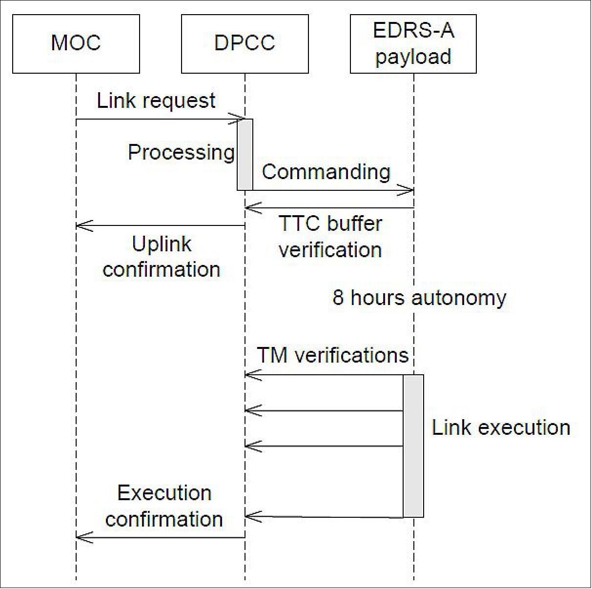
The link planning process of an optical inter satellite link only requires the execution of one FO; however, the process for a Ka-band link is difinitely more complex. While one flight procedure is executed to configure the RF components of the payload for the link, the steering of the inter-satellite antenna is a complex task. The antenna is commanded by entries of a time and a direction embedded into two tables with 1440 entries each. The on-board function interpolates between two entries of the active table while new entries can only be commanded into the inactive one. The processing is started at a commanded start entry of one table. Certainly this entry must have a feasible time in the future and an antenna direction that is reachable in time without exceeding speed limits. For link requests received at the DPCC eight hours before their execution the table entries are written into the inactive table and a table switch is planned at a time when all the entries for the upcoming eight hours are in the new active table (Figure 42a). For late requests or for the deletion of a link, the currently running table would have to be changed. Therefore, a new table for the next eight hours including the late request (link 8b in Figure 42c), or excluding the deleted link (link 6 in Figure 42b), is composed on ground and loaded to the inactive table on board. Afterwards the active table is switched to the new composed one.
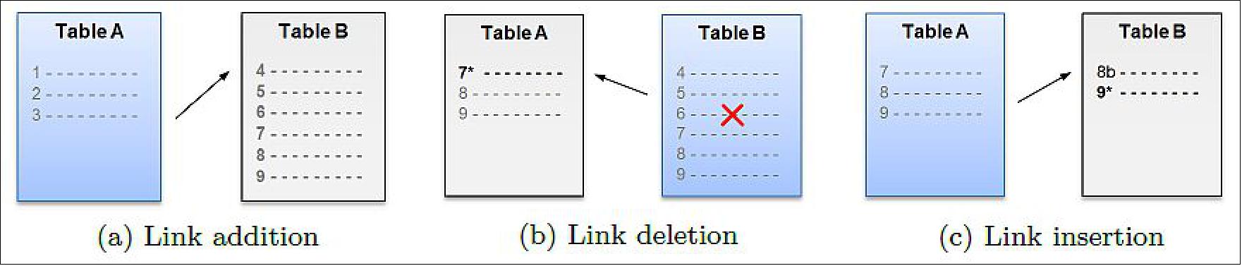
While the Ka-band link is always bidirectional, the LCT links are possible in return (from the target LEO satellite via EDRS to the ground), forward (to the LEO satellite), and bidirectional. The actual link commanding is similar in all three LCT link cases, but for forward and bidirectional links the binary data to be forwarded has to be uploaded to the DPU prior to link execution. This forward tasking data service is done via the normal commanding channel by telecommands containing 62 bytes of data. The filling of the DPU forward data buffer of five megabytes is planned by the LMS with a lower priority as the link commanding in order to not block the link execution.
Automated routine operations: In addition to the link operations a small number of routine operations are also performed automatically. These operations are also executed as time-tagged telecommands which are uploaded to the spacecraft eight hours in advance. Thereby the spacecraft autonomy of eight hours is ensured. Furthermore a synchronization between routine and link commands is needed.
The following routine operations are conducted by the DPCC autonomously from request provided by the MOC:
• LCT time synchronization
• On-orbit propagator
• LCT alignment matrix
• LCT park and unpark
• Ka-band antenna steering pause
Manual operations:
All other tasks are performed in a more classical manual operations approach. This is the case for all contingency operations as well as nominal operational tasks that are only performed rarely. For that members of the flight operations team will execute the FOP, and decide the timing and execution state. The telemetry verification can be done by display pages. But as the Automator is still used for generating the TC sets delivered to the Eutelsat SCC, a semi-automatic FOP execution is possible.
SA (Situational Awareness):
Being aware of the situation of all parts of the system is of the outmost significance of any spacecraft mission. Already in the classical operations concept, the spacecraft controller (SPACON) is monitoring the spacecraft's status in telemetry as well as the state of the ground components. The added complexity is caused by the reduced knowledge of the ongoing activities triggered by the automatic system. The operator is not the actor anymore, but an observer. And with EDRS being included in the GSOC multimission environment, the SPACON cannot monitor only EDRS at all times.
This new role reduces the situational awareness significantly. Mica Endsley defined the situation awareness (SA) as "the perception of the elements in the environment within a volume of time and space, the comprehension of their meaning and the projection of their status in the near future". 71) Although the work of Mica Endsley is focused on aviation, the principles can be transferred to spacecraft operations. Three levels of SA have been defined in her work: Level 1 - Perception of the elements in the environment, Level 2 - Comprehension of the current situation, and Level 3 - Projection of the future status. Adapted to the operational scenario the three levels can be understood as: 72)
• Level 1: Perceive the presence of a not nominal situation
• Level 2: Comprehension of the system's situation and the processes going
• Level 3: Projection of the future status.
In summary, the EDRS system is setting new speed levels, not only for data transmission from space, but also in the operations for GEO satellites. The innovative automated operations at DPCC are now starting to be in use for the first time and handle this challenging mission after the manual in-orbit test campaign of EDRS-A is completed. After the DPCC systems will have shown its capability in automatic operations, the next improvements will be assessed for EDRS-C. Additional routine operations, such as station keeping maneuvers, might be able to be automatized with these cutting edge concepts (Ref. 68).
IOV (In-Orbit Verification) of LCT for EDRS (Ref. 3):
EDRS operations will take advantage of the LEO-GEO OISL experiments between the GEO Alphasat satellite and the LEO Sentinel-1A/-2A satellites planned after the launch of the first Sentinel. The payload data rate requirement for the Sentinel-1A/-2A satellites is 600 Mbit/s, which is well within the capabilities of 2nd generation Tesat LCT. The objectives of these experiments with Alphasat and Sentinel-1A/-2A satellites are:
• to optimize the technical performances of the LEO-GEO OISL (including GEO-ground tests)
• to perform an early validation of the end-to-end data relay system, which includes the LEO-GEO OISL, the RF feeder link between Alphasat and its ground segment, and the interfaces and operations with the Copernicus ground segment.
The experience gained from these experiments will be taken into account during the IOV activities of the LCTs on board the Eutelsat-9B and EDRS-C satellites and for the validation of the end-to-end EDRS performances.
The approach for the IOV of the LCTs is as follows:
- LCT self-test: this test is performed during commissioning to check out the LCT performances after launch. A functional end-to-end test of the entire data transmit and receive chain (including the telescope and the coarse pointer) can be performed while the LCT is in parking position thanks to a mirror mounted in the parking position unit.
- IOV with an OGS Optical Ground Station): these trials are required in order to calibrate the LCT setting parameters (e.g., acquisition scanning parameters, misalignment matrix between satellite coordinate reference system and LCT coordinate reference system, clock offset and other propagator parameters, etc.) and to verify the full PAT (Pointing Acquisition and Tracking) performances (e.g., uncertainty cone, link acquisition time, etc.). The baseline is to use the ESA’s OGS on Tenerife Island (Spain) with some adaptations (Figure 9). As a mean of cross support, DLR’s mobile OGS can, on request, be used as backup. The DLR mobile OGS is intended for experimental space-to-ground optical links with GEO satellites (e.g. Alphasat) or lower altitude vehicles (e.g. Sentinel-1A, Sentinel-2A).
- IOV with LEO user satellite: these tests are to further fine tune the LCT setting parameters, and to validate the LEO-GEO O-OISL acquisition, tracking and communications performances. The LCTs on board the LEO Sentinel-1A/-2A satellites will be used as counter terminals.
After successful completion of the remaining commissioning activities (e.g., EDRS space segment with EDRS ground segment commissioning, joint EDRS Copernicus service commissioning) to verify the full operational capability of the overall EDRS system with the user (i.e., Copernicus), the EDRS will enter into operational phase by mid of 2015.
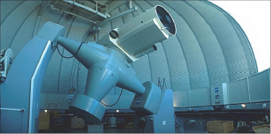
EDRS services
The data relay services offered by the EDRS will significantly improve the European capabilities for transmitting user data from user space assets (e.g., Earth observation LEO satellites) in terms of user data volume and timeliness. Furthermore, the EDRS offers flexibility in the manner the user data is transmitted. Compared to conventional direct LEO-to-ground downlinks where the access time for communications per ground station is restricted by the visibility time (around 10% of the LEO satellite’s orbital period), data relay via GEO satellite increases substantially the available communication time to the LEO user satellites thanks to the long visibility periods inherently available from the GEO location (e.g., one GEO satellite already enhances the visibility time to around 50% of the LEO satellite’s orbital period). - Besides, the data relay downlink offers a wide European coverage efficiency. Data can thus be downlinked directly to DGS and the FLGS or user’s own ground stations, which reduces the user data repatriation costs and facilitates data dissemination to final users (Ref. 3).
In addition to the downlink capabilities, the EDRS can also provide quasi real-time access from ground to the LEO user satellite during periods of direct line-of-sight, which can be used to reconfigure the EO (Earth observation) LEO payload / satellite, and hence, shortening the reaction time of EO LEO satellites in case of emergency events (i.e., request on-demand).
The EDRS provides different types of optical and Ka-band services, using the OISLs (Optical Intersatellite Links) and Ka-ISLs (Ka-band Intersatellite Links), respectively (Figures 29 and 30). Both ISLs between the LEO user and the GEO satellites are bi-directional, and are referred as the RTN (Return link), from LEO user to GEO) and the FWD (Forward link), from GEO to the LEO user. The EDRS-A and the EDRS-C payloads offer Optical services, whereas the Ka-band services are implemented on the EDRS-A payload only.
The Optical services are split into RTN and FWD services. The Optical RTN service is a high data rate channel transferring the user data from the LEO user satellite to ground via the GEO relay satellite. The user data rate for the Optical RTN service is 600 Mbit/s for the so-called Sentinel mode (e.g., for Sentinel-1A and Sentinel-2A) and 1.8 Gbit/s for the so-called “advanced mode” to cover future user needs. The EDRS RF feeder link is accordingly dimensioned to support these user data rate requirements. The Optical FWD service is a low data rate channel (limited by the uplink TM/TC channel) to transmit telecommands to the LEO user satellite in quasi-real time (e.g., for reconfiguration of the Earth observation LEO payload / satellite).
Alternatively to the Optical RTN service, the EDRS also offers the Ka-ISL RTN service, which relays the user data from the LEO user satellite to ground at a user data rate up to 300 Mbit/s.
Daily capacity (Terabyte/day) | Sentinel mode | Advanced mode |
EDRS-A node | 5.4 TB/day | 16.2 TB/day |
EDRS-A and EDRS-C nodes | 10.8 TB/day | 32.4 TB/day |
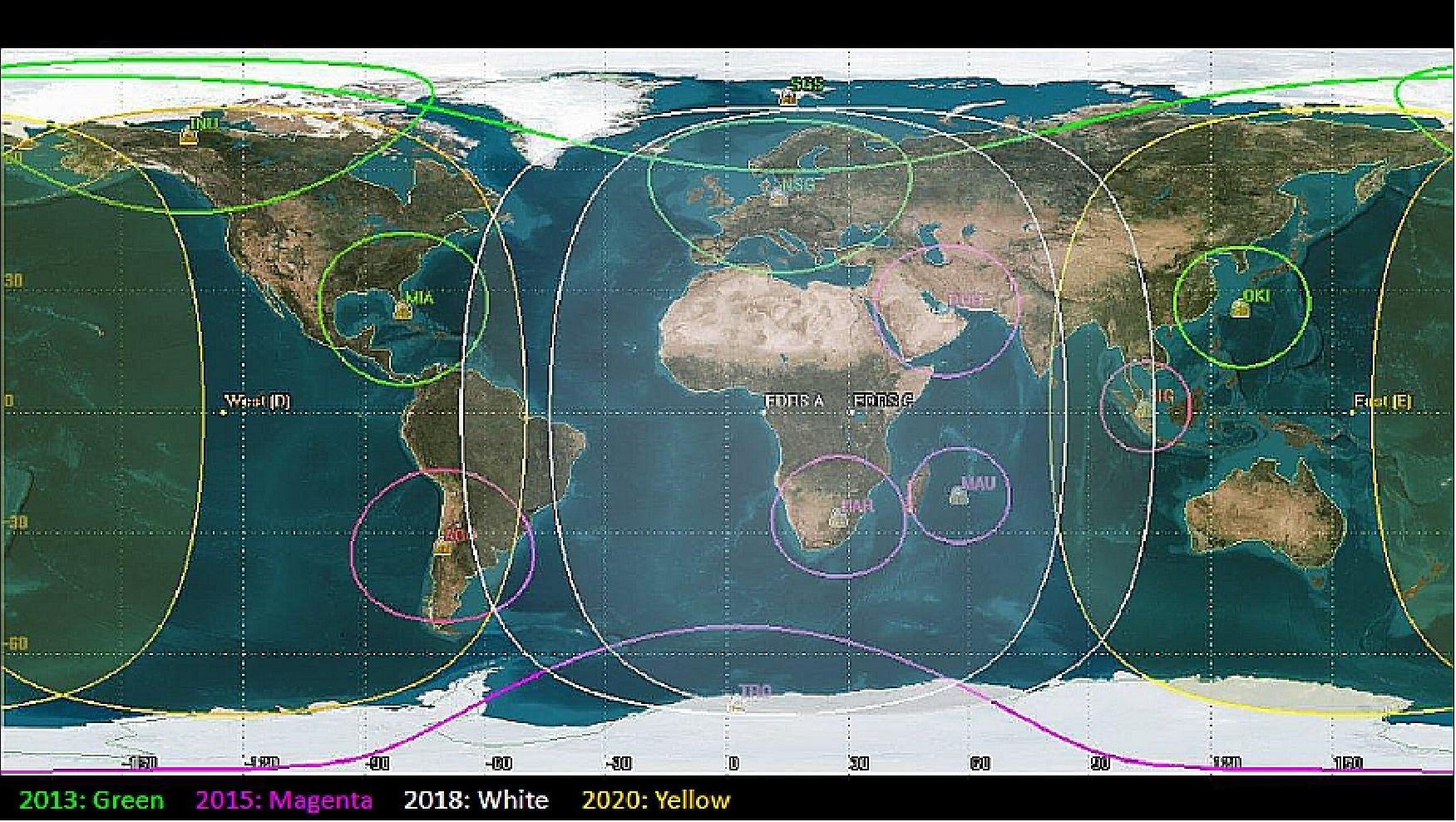
• 2013: 5 ground based Teleports
• 2015: 11 ground based Teleports
• 2019: full Service EDRS A/C
• 2022: full Service EDRS A/C/D/E.
1) “European Data Relay Satellite System (EDRS),” ESA, 2009, URL: http://multimeter's/docs/telecom/EDRS_factitious
2) “ESA issues open competition for EDRS phase B/C/D/ E1,” Feb. 26, 2010, URL: http://telecommand/telecom/WWW/object/MUXCam?objected=30248
3) Michael Witting, Harald Household, Andrew Merell, Jean-Pascal Legality, Joseph Perigees, Jean Michel Later, Cedric Sal enc, Khalil Kabul, Helli Grues, Francois Ga rat, Hermann Ludwig Mueller, Silvia Mezzos, Rolf Meyer, Bjorn Gulch, Sabine Philippa-May, Ankle Pa gels-Keep, BSA Helen, Matthias Ligand, Marc Lead stone, Gerald Rickert, Georg Whetstone, Ludwig Lax, Lory Gerard, Dominique Ponced, Rolf Mag er, Klaus Schoenberg, Frank Heine, Stefan SEL, Konrad Panza, Her wig Zach, Hartman Campfire, Alexander Schneider, Ignacio Gutierrez Can as, Cristina Arias Perez, Herbert Sc huff, “Status of the European Data Relay Satellite System,” Proceedings of the ICSOS (International Conference on Space Optical Systems and Application) 2012, Ajaccio, Corsica, France, October 9-12, 2012, URL: http://icsos2012.nict.go.jp/pdf/1569603307.pdf
4) ”RUAG Space Supplies the Brain and Heat Protection for the EDRS-C Satellite,” Satnews Daily, 1 August 2019, URL: http://www.satnews.com/story.php?number=1610289995
5) ”EDRS-C mated with launcher,” ESA, 30 July 2019, URL: http://www.esa.int/Our_Activities
/Telecommunications_Integrated_Applications/EDRS/EDRS-C_mated_with_launcher
6) ”Next satellite in the European Data Relay System is fuelled,” ESA, 26 July 2019, URL: http://www.esa.int/Our_Activities/Telecommunications_Integrated_Applications
/Next_satellite_in_the_European_Data_Relay_System_is_fuelled
7) ”Launch of the second SpaceDataHighway satellite,” Airbus Press Release, 6 May 2019, URL: http://www.securecommunications-airbusds.com/
news-and-events/news/755756ced712728fff63ecbbc3f2b3c8/
8) ”Latest node in the European Data Relay System passes antenna tests,” ESA, 23 April 2019, URL: http://m.esa.int/Our_Activities/Telecommunications_Integrated_Applications/
Latest_node_in_the_European_Data_Relay_System_passes_antenna_tests
9) ”EDRS-C antenna performance verification at the Airbus CATR facility in Germany,” ESA, 16 April 2019, URL: http://m.esa.int/spaceinimages/Images/2019/04/
EDRS-C_antenna_performance_verification_at_the_Airbus_CATR_facility_in_Germany2
10) ”EDRS-C on the home stretch,” ESA, 20 June 2018, URL: http://www.esa.int/Our_Activities/
Telecommunications_Integrated_Applications/EDRS/EDRS-C_on_the_home_stretch
11) Peter B. de Selding, ”Satellite carrying laser-optical data relay service and Hylas-3 Ka- payload faces new delay,” Space Intel Report, 26 June 2017, URL: https://www.spaceintelreport.com/
satellite-carrying-commercial-laser-optical-data-relay-service-hylas-3-payload-face-new-delay/
12) “European Data Relay Satellite,” ESA Bulletin, No 146, May 2011, p. 93
13) “EDRS Space Data Highway,” URL: http://www.edrs-spacedatahighway.com/
14) “Announcement of Opportunity for Hosted Payload on board EDRS-C Satellite,” ESA, Sept. 22, 2011, URL: http://telecom.esa.int/telecom/media/document/2011%2009%2022%20
EDRS%20AO%20workshop%20presentation%20-%20full%20set%20-%20final.pdf
15) “EDRS: An independent data-relay system for Europe becoming reality,” ESA, Oct. 4, 2011, URL: http://telecom.esa.int/telecom/www/object/index.cfm?fobjectid=31346
16) “Europe's 'data superhighway' in space sets sail,” DLR, June 25, 2012, URL: http://www.dlr.de/dlr/en/desktopdefault.aspx/tabid-10081/151_read-4006/year-all/
17) “Astrium contracts DLR for major parts of the EDRS ground network,” Astrium, June 25, 2012, URL: https://web.archive.org/web/20140116124317/http://www.astrium.eads.net/en/press_centre/astrium-contracts-dlr-for-major-parts-of-the-edrs-ground-network.html
18) “SES TechCom, Astrium and DLR achieve milestone for information highway in space,” SES TechCom, June 27, 2012, URL: http://www.innovation.public.lu/en/actualites/2012/06/ses/index.html
19) Akos Hegyi, Martin Agnew, Judith Metschies, “SpaceDataHighway Will Redefine High-Speed Data Transfer,” Earth Imaging Journal, July/August 2012, pp. 36-40, URL:
http://www.edrs-spacedatahighway.com/tl_files/pdf/EarthImagingJournal_UASArticle_Final.pdf
20) “EDRS space network ready to go ahead,” ESA, Nov. 23, 2012, URL: http://telecom.esa.int/telecom/www/object/index.cfm?fobjectid=32072
21) “OHB System AG and Astrium GmbH sign contract for the delivery of an EDRS satellite,” May 28, 2013, URL: http://www.edrs-spacedatahighway.com/news/items/
ohb-system-ag-and-astrium-gmbh-sign-contract-for-the-delivery-of-an-edrs-satellite
22) “First EDRS node on track for launch,” ESA, Oct. 29, 2014, URL: http://www.esa.int/Our_Activities
/Telecommunications_Integrated_Applications/First_EDRS_node_on_track_for_launch
23) “European Data Relay System confirms services for Copernicus in cooperation with the European Commission,” ESA, Feb. 25, 2015, URL: http://www.esa.int/Our_Activities/
Observing_the_Earth/Copernicus/European_Data_Relay_System_confirms
_services_for_Copernicus_in_cooperation_with_the_European_Commission
24) ”EDRS-A and its laser are ready to fly,” ESA, Dec. 9, 2015, URL: http://www.esa.int/Our_Activities/Telecommunications_Integrated_Applications
/EDRS/EDRS-A_and_its_laser_are_ready_to_fly
25) ”First SpaceDataHighway Laser Relay in Orbit,” ESA, Jan. 30, 2016, URL: http://www.esa.int/Our_Activities/Telecommunications_Integrated_Applications
/EDRS/First_SpaceDataHighway_laser_relay_in_orbit
26) http://www.russianspaceweb.com/2015.html
27) Harald Hauschildt, Francois Garat, Heli Greus, Khalil Kably, Jean-Pascal Lejault, Hermann Ludwig Moeller, Andrew Murrell, Josep Perdigues, Michael Witting, Bas Theelen, Matthias Wiegand, Akos Hegyi, “European Data Relay System – one year to go,” Proceedings of ICSOS 2014 (International Conference on Space Optical Systems and Applications), Kobe, Japan, May 7-9, 2014
28) ”Successful launch of the first laser telecommunication satellite of the ‘SpaceDataHighway’,” EDRS Space Data Highway, Feb. 1, 2016, URL: http://www.edrs-spacedatahighway.com
/news/items/success-launch
29) ”EDRS-C successfully launched!,”ESA, 6 August 2019, URL: https://www.esa.int/
Our_Activities/Telecommunications_Integrated_Applications/EDRS-C_successfully_launched
30) ”Successful launch of the second SpaceDataHighway satellite on Ariane 5,” Airbus Press Release, 7 August 2019, URL: https://web.archive.org/web/20210410184326/https://www.airbus.com/newsroom/press-releases/en/2019/08/successful-launch-of-the-second-spacedatahighway-satellite-on-ariane-5.html
31) Stephen Clark, ”Launch Schedule: Ariane 5 • Intelsat 39 & EDRS-C,” Spaceflight Now, 6 August, 2019, URL: https://spaceflightnow.com/launch-schedule/
32) “Arianespace selected by Airbus Defence and Space to launch EDRS-C satellite,” Arianespace, March 19, 2015, URL: http://www.arianespace.com/news-press-release/2015/3-18-2015-EDRS.asp
33) ”European system speeds data flow with 50,000 links,” ESA / Applications / Telecommunications & Integrated Applications, 24 June 2021, URL: https://www.esa.int/Applications/Telecommunications_Integrated_Applications
/European_system_speeds_data_flow_with_50_000_links
34) ”EDRS: the space data highway,” ESA Applications, 21 January 2021, URL: https://www.esa.int/ESA_Multimedia/Videos/2021/01/EDRS_the_space_data_highway
35) ”Data-relay satellite beams at light speed,” ESA Applications, 16 July 2020, URL: https://www.esa.int
/Applications/Telecommunications_Integrated_Applications/Data-relay_satellite_beams_at_light_speed
36) ”Data-relay satellite ready for service,” ESA / Applications / Telecommunications & Integrated Applications, 29 May 2020, URL: http://www.esa.int/Applications/Telecommunications_Integrated_Applications
/Data-relay_satellite_ready_for_service
37) ”Second space data highway satellite set to beam,” ESA / Applications / Telecommunications & Integrated Applications, 23 January 2020, URL: http://www.esa.int/Applications/Telecommunications_Integrated_Applications
/Second_space_data_highway_satellite_set_to_beam
38) ”SpaceDataHighway demonstrates its unique timeliness capability during live event,” Airbus, 22 July 2019, URL: https://web.archive.org/web/20210926132459/https://www.airbus.com/newsroom/news/en/2019/07/spacedatahighway-demonstrates-its-unique-timeliness-capability-during-live-event.html
39) ”Airbus to run UK MOD’s land C4ISR test centre,” Airbus Press Release, 19 July 2019, URL: https://www.airbus.com/content/dam/corporate-topics/publications
/press-release/EN-Airbus-CIS-Press-Release-UK-C4ISR-test-centre.pdf
40) Airbus Signs Five Year C4ISR Contract with the UK Ministry of Defence,” Satnews Daily, 19 July 2019, URL: http://www.satnews.com/story.php?number=1135037660#
41) ”Next satellite in the European Data Relay System arrives in Kourou,” ESA, 18 June 2019, URL: http://www.esa.int/Our_Activities/Telecommunications_Integrated_Applications
/Next_satellite_in_the_European_Data_Relay_System_arrives_in_Kourou
42) ”First satellite in European SpaceDataHighway forges 20,000 successful laser links,” ESA, 2 April 2019, URL: http://m.esa.int/Our_Activities/Telecommunications_Integrated_Applications
/First_satellite_in_European_SpaceDataHighway_forges_20_000_successful_laser_links
43) ”Europe’s laser satellite in ship shape for 2019,” ESA, 23 January 2019, URL: http://m.esa.int/Our_Activities/Telecommunications_Integrated_Applications
/EDRS/Europe_s_laser_satellite_in_ship_shape_for_2019
44) ”The SpaceDataHighway Accomplishes 10,000 Successful Laser Connections,” Satnews Daily, 18 May 2018, URL: http://www.satnews.com/story.php?number=1250887753
45) ”10,000 laser links between satellites established,” Tesat Spacecom, 11.04.2018, URL: https://www.tesat.de/en/media-center/press/news/
697-pi1289-10-000-laser-links-between-satellites-established
46) ”Start of service for Europe’s SpaceDataHighway,” ESA, 23 Nov. 2017, URL: http://m.esa.int/Our_Activities/Telecommunications_Integrated_Applications
/EDRS/Start_of_service_for_Europe_s_SpaceDataHighway
47) ”Tesat-Spacecom and BridgeSat Announce Partnership to Provide Total Optical Communications Solution for Commercial Satellite Operators,” Tesat Spacecom, 11 Sept. 2018, URL: https://www.tesat.de/en/media-center/press/news/529-pi1284-tesat-bridgesat-announce-partnership
48) ”Laser comms riding on the SpaceDataHighway for APAC coverage from Airbus Defence and Space,” Satnews Daily, March 8, 2017, URL: http://www.satnews.com/story.php?number=1020301978
49) ”Start of service for Europe’s SpaceDataHighway,” ESA, Nov. 23, 2016, URL: http://m.esa.int/Our_Activities/Telecommunications_Integrated_Applications
/EDRS/Start_of_service_for_Europe_s_SpaceDataHighway
50) ”The SpaceDataHighway is Open for Traffic,” Airbus DS, Nov. 23, 2016, URL: https://airbusdefenceandspace.com/newsroom/
news-and-features/the-spacedatahighway-is-open-for-traffic/
51) ”Europe’s SpaceDataHighway relays first Sentinel-1 images via laser,” ESA, June 1, 2016, URL: http://m.esa.int/Our_Activities/Telecommunications_Integrated_Applications/
EDRS/Europe_s_SpaceDataHighway_relays_first_Sentinel-1_images_via_laser
52) ”EDRS-A testing the waters,” ESA, April 15, 2016, URL: http://www.esa.int/Our_Activities
/Telecommunications_Integrated_Applications/EDRS/EDRS-A_testing_the_waters
53) ”First Quasi-Real-Time Demonstration of an end-to-end delivery SAR image,” EDRS Space Data Highway, Feb. 29, 2016, URL: http://www.edrs-spacedatahighway.com/news/items/actionable-information
54) ”Brazil coast via laser beam,” ESA, March 2, 2016, URL: http://www.esa.int/spaceinimages/Images/2016/03/Brazil_coast_via_laser_beam
55) ”First Space Data Highway laser relay in orbit,” ESA, Jan. 30, 2016, URL: http://www.esa.int/Our_Activities/Telecommunications_Integrated_Applications
/EDRS/First_SpaceDataHighway_laser_relay_in_orbit
56) D. Poncet, S. Glynn, F. Heine, “Hosting the first EDRS Payload,” Proceedings of the ICSO (International Conference on Space Optics), Tenerife, Canary Islands, Spain, Oct. 7-10, 2014, URL: http://congrexprojects.com/Custom/ICSO/2014/Papers/1.%20Tuesday%207%20October/
Session%202D%20Free%20Space%20Optical%20Comms/1.65575_Poncet.pdf
57) “EDRS makes room for Hylas-3,” ESA, July 12, 2012, URL: http://www.esa.int/esaCP/SEMVN8KXB4H_index_0.html
58) Norbert Dörflinger, Matthias Motzigemba, Herwig Zech, Wolfram Lütke, ”A new chapter begins for EO-Missions Hybrid Optical/RF Payloads for Data Relay Applications becomes operational,” Proceedings of the 66th International Astronautical Congress (IAC 2015), Jerusalem, Israel, Oct.12-16, 2015, paper: IAC-15 B2.6.2
59) Dirk Giggenbach, Ricardo Barrios, Florian Moll, Ramon Mata Calvo,Sergei Bobrovskyi, Felix Huber, Nighat F. D. Johnson-Amin, Frank Heine, Mark Gregory, “EFAL: EDRS Feeder Link from Antarctic Latitudes - Preliminary Results of Site Investigations, Availability, and System Requirements,” European Data Relay System – one year to go,” Proceedings of ICSOS 2014 (International Conference on Space Optical Systems and Applications), Kobe, Japan, May 7-9, 2014, URL: http://elib.dlr.de/89312
/1/__192.168.178.179_NAS-Share_OP_Projects_publications_All_2014-Giggenbach
-CNF-ICSOS-EFAL_results_Paper_Giggenbach_2014_EFAL-results_ICSOS2014.pdf
60) Stefan Seel, Hartmut Kämpfner, Frank Heine, Daniel Dallmann, Gerd Mühlnikel, Mark Gregory, Martin Reinhardt, Karen Saucke, Juri Muckherjee, Uwe Sterr, Bernhard Wandernoth, Rolf Meyer , Reinhard Czichy, “Space to Ground Bidirectional Optical Communication Link at 5.6 Gbit/s and EDRS Connectivity Outlook,” 2011 IEEE Aerospace Conference, Big Sky, MT, USA, March 5-12, 2011
61) M. Gregory, F. Heine, H. Kämpfner , R. Meyer , R. Fields , C. Lunde, “Tesat laser communication terminal performance results on 5.6 Gbit coherent intersatellite and satellite to ground links,” ICSO 2010 (International Conference on Space Optics), Rhodes, Greece, October 4-8, 2010, URL: http://congrex.nl/icso/Papers/Session%208a/FCXNL-10A02-2012697-1-GREGORY_ICSO_PAPER.pdf
62) Amy Svitak, “Inside The World's First Space-Based Commercial Laser-Relay Service,” Aviation Week, March 12, 2015, URL: http://aviationweek.com/SpaceLaserRelay
63) Mark Gregory, Frank Heine, Hartmut Kämpfner, Robert Lange, Michael Lutzer, Rolf Meyer, “Commercial optical inter-satellite communication at high data rates,” Optical Engineering, Vol. 51, No 3, March 13, 2012, pp: 031202-031202-7
64) Zoran Sodnik, Marc Sans, “Extending EDRS to Laser Communication from Space to Ground,” Proceedings of the ICSOS (International Conference on Space Optical Systems and Application) 2012, Ajaccio, Corsica, France, October 9-12, 2012, URL: http://icsos2012.nict.go.jp/pdf/1569600353.pdf
65) Matthias Motzigemba, “Improvement of information latency in EO-Missions with the use of hybrid Laser/RF systems,” Proceedings of the 64th International Astronautical Congress (IAC 2013), Beijing, China, Sept. 23-27, 2013, paper: IAC-13-B2.2.3.9
66) Martin Reinhardt, Konrad Panzlaff, Karl-Georg Friederich, Frank Heine, Roland Himmler, Klaus Maier, Eberhard Möss, Clive Parker, Simon McAdam, Jason Slack, Colin Howley, Rolf Meyer, “High Precision Encoders for GEO Space Applications,” Proceedings of the ICSOS (International Conference on Space Optical Systems and Application) 2012, Ajaccio, Corsica, France, October 9-12, 2012, URL: http://icsos2012.nict.go.jp/pdf/1569587555.pdf
67) “DLR to Implement Major Parts of Ground Network,” June 25, 2012, URL:
http://www.edrs-spacedatahighway.com/news/items/dlr-to-implement-major-parts-of-ground-network
68) Jan-Christoph Scharringhausen, Andreas Kolbeck, Thorsten Beck, ”A Robot on the Operator's Chair — The Fine Line Between Automated Routine Operations and Situational Awareness,” Proceedings of the 14th International Conference on Space Operations (SpaceOps 2016), Daejeon, Korea, May 16-20, 2016, paper: AIAA 2016-2508, URL: http://arc.aiaa.org/doi/pdf/10.2514/6.2016-2508
69) Thorsten Beck, Michael Schmidhuber, Jan-Christoph Scharringhausen, ”Automation of Complex Operational Scenarios -Providing 24/7 Inter-Satellite Links with EDRS,” Proceedings of the 14th International Conference on Space Operations (SpaceOps 2016), Daejeon, Korea, May 16-20, 2016, paper: AIAA 2016- 2417, URL: http://arc.aiaa.org/doi/pdf/10.2514/6.2016-2417
70) Tobias Göttfert, Boris Grishechkin, Maria T. Wörle, Christoph Lenzen, ”The Link Management System for the European Data Relay Satellite Program ,” Proceedings of the 14th International Conference on Space Operations (SpaceOps 2016), Daejeon, Korea, May 16-20, 2016, paper: AIAA-2016-2645, URL: http://arc.aiaa.org/doi/pdf/10.2514/6.2016-2645
71) Mica R. Endsley, ”Design and Evaluation for Situation Awareness Enhancement,” Proceeding of the Human Factors Society, 32nd Annual Meeting, Santa Monica, CA, USA, Human Factors and Ergonomics Society, Annual Meeting October1988, pp. 97-101
72) Mica R. Endsley, ”Situation Awareness,” The Oxford Handbook of Cognitive Engineering, Edited by John D. Lee and Alex Kirlik, Oxford Univ. Press, New York, May 2013, pp. 88-108.
The information compiled and edited in this article was provided by Herbert J. Kramer from his documentation of: ”Observation of the Earth and Its Environment: Survey of Missions and Sensors” (Springer Verlag) as well as many other sources after the publication of the 4th edition in 2002. - Comments and corrections to this article are always welcome for further updates (herb.kramer@gmx.net).
Launch Mission Status Spacecraft Laser Communication Terminal Ground Segment EDRS Services References Back to Top