DSX (Demonstration and Science Experiments)
EO
Mission complete
USAF
Fluxgate magnetometer
Quick facts
Overview
| Mission type | EO |
| Agency | USAF |
| Mission status | Mission complete |
| Launch date | 25 Jun 2019 |
| End of life date | 31 May 2021 |
| Instruments | Fluxgate magnetometer |
| CEOS EO Handbook | See DSX (Demonstration and Science Experiments) summary |
DSX (Demonstration and Science Experiments) in MEO
Spacecraft Launch Mission Status Sensor Complement Technology Introduction Ground Segment
References
DSX is a small spacecraft mission of the U.S. AFRL (Air Force Research Laboratory), Albuquerque, NM, USA. The objective is to research technologies needed to significantly advance Department of Defense (DoD) capabilities to operate spacecraft in the harsh radiation environment of MEO (Medium-Earth Orbits). The ability to operate effectively in the MEO environment significantly increases the DoD‘s capability to field space systems that provide persistent global space surveillance and reconnaissance, high-speed satellite-based communication, lower-cost GPS navigation, and protection from space weather and environmental effects on a responsive satellite platform. 1) 2) 3) 4) 5)
The three DSX physics-based research/experiment areas are:
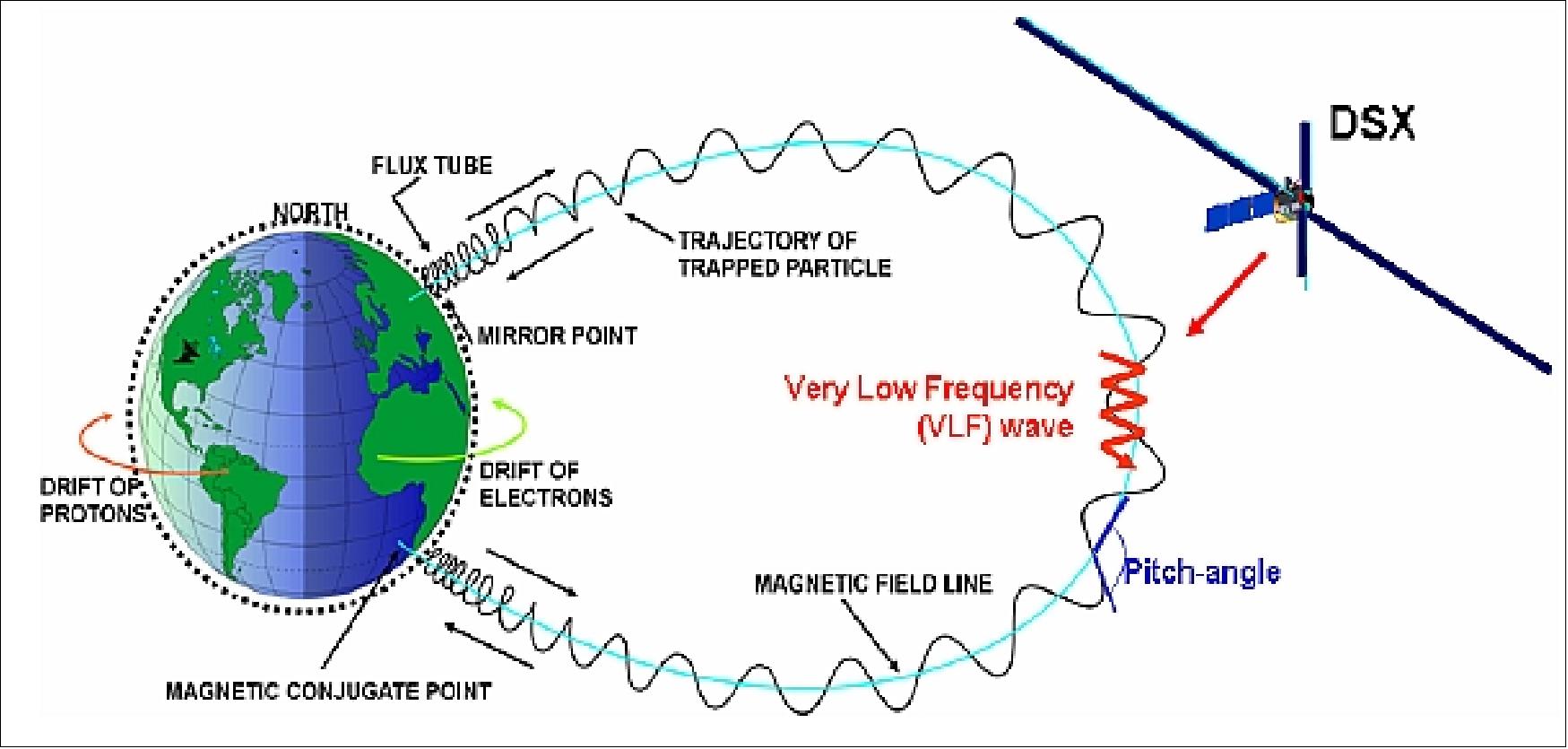
1) WPIx (Wave Particle Interaction Experiment): Researching the physics of VLF (Very-Low-Frequency) electromagnetic wave transmissions through the ionosphere and in the magnetosphere and characterizing the feasibility of natural and man-made VLF waves to reduce and precipitate space radiation.
2) SWx (Space Weather Experiment): Characterizing, mapping, and modeling the space radiation environment in MEO, an orbital regime attractive for future DoD, Civil, and Commercial missions.
3) SFx (Space Environmental Effects Experiment): Researching and characterizing the MEO space weather effects on spacecraft electronics and materials.
The DSX mission will provide an important database from which future designers of space missions intended to operate in the MEO environment can rely. These are:
• New climatology models for satellite design in MEO will be developed as a result of DSX
• Key wave-particle interaction components of global radiation belt space situational awareness and forecast models will be developed and validated from the DSX data
• New methods for ruggedization of electronics for MEO will be tested.
Beyond the inherent value of the scientific experiments, DSX will also serve as a pathfinder for future DoD rapid response missions, by developing and demonstrating both technologies and processes that enable low-cost and rapid integration of one-of-a-kind R&D satellites and operational systems. DSX addresses the rapid integration problem through the use of an innovative network based infrastructure, the Planning System Inc. (PSI) Network Data Acquisition System (NDAS), for implementation of bus and payload box connectivity, as well as distributed remote sensor payloads on large deployable structures. 6)
Background
The mission was originally conceived by AFRL researchers in 2003 to conduct physics-based experiments, and was selected as an AFRL mission in 2004. With primary funding from AFRL, DSX enjoys additional support from DARPA (Defense Advanced Research Projects Agency) and NASA. Note: Prior to 2005 DSX was known as `Deployable Structures Experiment' mission.
The MEO region is a relatively unused and unexplored domain of spaceflight with regard to the radiation environment requiring investigations for model development (energetic particle distributions, VLF injection, propagation, wave particle interaction processes, etc.), and to study the effects of exposure on the spacecraft electronics and materials. 7) 8) 9) 10) 11) 12)
The MEO region is of great interest to DoD because it significantly increases the potential to field future space systems that provide persistent global targeting-grade space surveillance, high-speed, satellite-based communication, lower-cost global positioning system navigation, and protection from space weather on a responsive satellite platform. The MEO orbit with its longer spacecraft contact periods (than in LEO) is also being studied and considered by NASA/NOAA and other agencies for future integrated concepts of environmental (weather) satellite missions. The uninterrupted Earth coverage requirements of many missions are making the MEO range attractive for a number of observation services.
To address the space access aspect of the rapid-response problem, DSX utilizes an ESPA (EELV Secondary Payload Adapter) capability as a platform for highly-capable small and medium free-flying satellites (or ESPASats) that have plentiful and relatively inexpensive launch opportunities on EELV as secondary payloads. Note: The first flight of ESPA took place on the STP-1 mission of DoD with a launch on March 9, 2007 (6 vehicle launch: Orbital Express (OE), MidSTAR-1, STPSat-1, NPSat-1, CFESat, and FalconSat-3). 13) 14)
Spacecraft
The DSX spacecraft is flying on the HSB (Host Spacecraft Bus), provided by SNC (Sierra Nevada Corporation), of Louisville, CO [note: in 2008, SNC acquired MSI (MicroSat Systems, Inc.) of Littleton, CO which was awarded a contract to build DSX in 2007]. The DSX flexible design structure (a derivative of MSI's modular TacSat-2 bus) maximizes the compatibility with numerous launch vehicles. 15) 16)
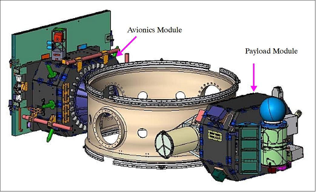
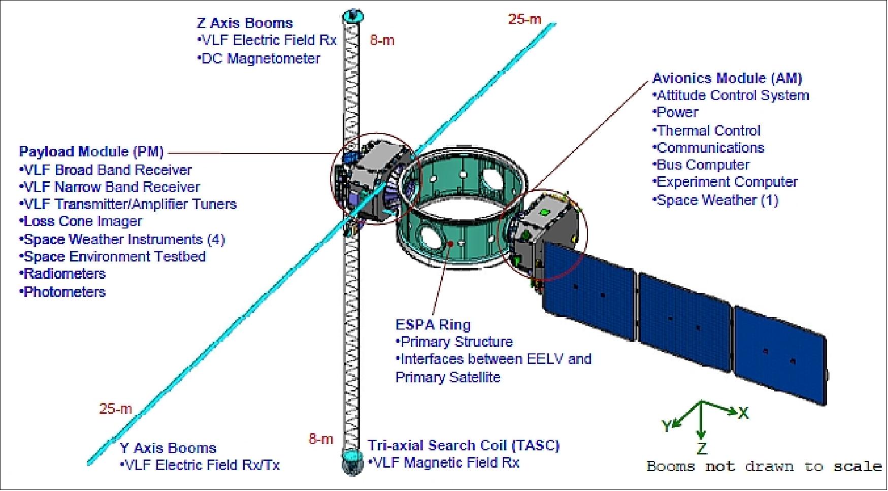
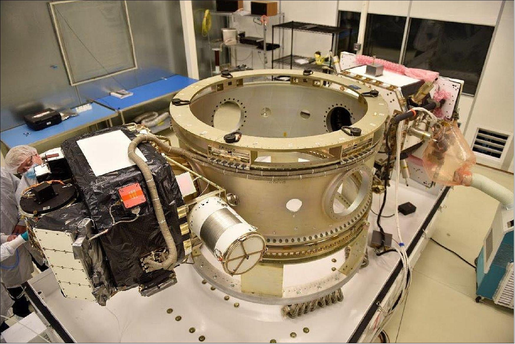
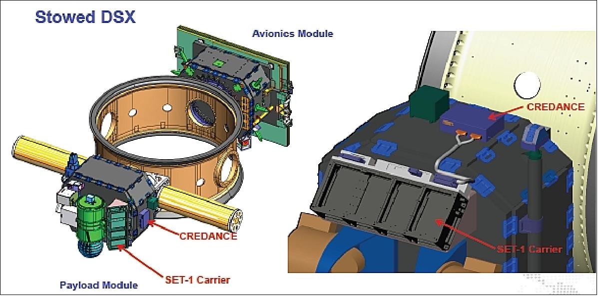
The HSB consists of the AM (Avionics Module), the PM (Payload Module) structure and the harness attached to the ESPA (EELV Secondary Payload Adapter) ring connecting the two modules together electrically. The AM is essentially the spacecraft bus with all the requisite subsystems (communications, power, thermal, ADCS (Attitude Determination and Control Subsystem), C&DH (Command and Data Handling), etc). It also houses the HEPS instrument, the ECS (Experimental Computer System), and the radiometers and photometers. The PM contains all the DSX specific components, except those just mentioned, along with the HSB Magnetometer and IMU (Inertial Measurement Unit).
The modules are mechanically bolted to the ESPA ring via a 39 cm bolt circle on two opposing ports of the DSX four port ESPA ring. DSX will fly the ESPA ring with both AM and PM attached at all times; the AM and PM will not separate. The AM and PM are each mechanically connected to the ESPA ring via a conical adapter, part of SNC’s module design, a SoftRide system developed by CSA Engineering for shock and vibration suppression and attenuation. The DSX in its stowed configuration is shown in Figure 2.
DSX has no propulsion, GPS unit, or star trackers. DSX does have an IMU, three sun sensors, and a magnetometer (in addition to the VMAG unit) for ADCS. The spacecraft is 3-axis stabilized.
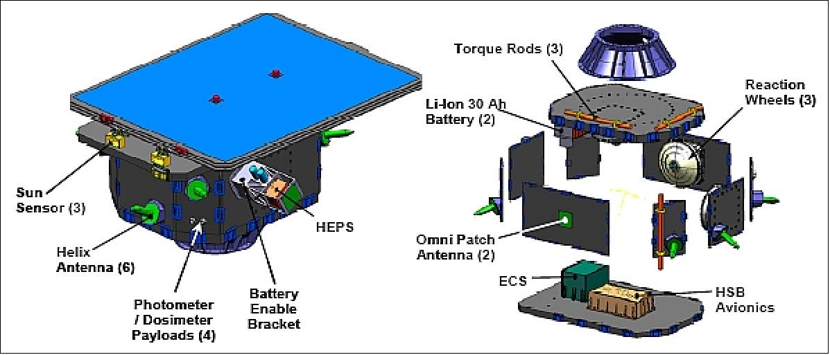
EPS (Electrical Power Subsystem): EPS consists of two Li-ion batteries, each of 30 Ah capacity, designed and manufactured by Yardney, Inc., a fixed, single wing, three panel solar array (with composite facesheets and Al honeycomb core) with triple junction GaAs cell technology, an efficiency of 28.5% at BOL (Beginning of Life), and the associated switches, diodes, and wiring.
The thermal subsystem consists of closed-loop heaters, white paint (AZ-93 or Alion Z-93) on the Y-boom canisters, and multi-layer insulation (MLI, 12 layers – 1 black Kapton, 10 Mylar, 1 AL Kapton). White coatings (Z-93C55) and black coatings (MH55-ICP) coat the structural surfaces of the AM and PM (black on the outside, white on the inside with an emissivity > 0.8). The ESPA ring is an all aluminum structure that serves as a large heat sink for the DSX spacecraft. DSX also has 63 temperature sensors distributed around the spacecraft with 47 of them as AD590s and 16 of them as PRT (Platinum Resistance Thermometers). Predicted temperatures for the DSX range from a max cold of – 116ºC for the Y and Z antennas to a max hot of 45ºC for the CXS-810C L-3 SGLS (Space Ground Link Subsystem) radio. The duty cycle for the heaters is no greater than 72%.
The structures and mechanisms subsystem of DSX consists of the AM structure, the PM structure, the ESPA ring, solar array panels, and the associated bulkheads and brackets. The margins of safety inherent in the designs are 8.5 g’s in two directions simultaneously which worst case is 12 g’s in each of three directions individually. The ultimate factor of safety is 1.4. The ESPA ring was qualified for flight for the STP-1 Mission and the qualification test data correlated to FE (Finite Element) models. DSX’s ESPA ring has a few modifications (4 port boss ports vs. the original 6 flange ports), so the DSX PMO had CSA engineering perform a Qualification by FE Analysis for the new design that showed a positive margin with a safety factor of 2.0 for the same testing conditions as STP-1’s qualification tests and the basic DSX design. The AM and PM flight structures were workmanship tested by subjecting them to sine burst levels up to 14.4 g (1.2 safety factor) with mass simulators in place of payloads.
C&DH (Command and Data Handling): C&DH and the communications subsystem consists of the SGLS CXS-810C radio, built by L-3 Communications Inc., the IAS (Integrated Avionics System), built by SEAKR Engineering Inc., the AM, PM, and the ESPA harnesses, built by Cicon Engineering Inc., the ECS (Experimental Computer System), built by Planning Systems Inc. (PSI), space-qualified RF switches, couplers, and diplexers, six helical antennas, and two omni patch antennas.
RF communications: The CXS-810C is the SGLS transponder radio with a BAE provided RAD-750 processor, providing SGLS uplink at 2 kbit/s and SGLS downlink up to 2 Mbit/s with ranging capability. The uplink and downlink signals will be encrypted. With an orbit of 6,000 km x 12,000 km, the uplink margin will be 23.2 dB worst case at 2 kbit/s and the worst case downlink margin will be 5.0 dB for safe mode at 500 bit/s and 5.1 dB in nominal operations at 1 Mbit/s. The worst case ranging margin will be 8.1 dB. The L-band command uplink operates at 2 kbit/s and can be received by either of the two RHCP (Right Hand Circular Polarization) patch antennas for approximately 4π steradian coverage. The six helical antennas are high data rate downlink only and are spaced around the AM structure and each has a 64º FOV (Field of View).
ADCS consists of the VMAG (Vector Fluxgate Magnetometer), an IMU ( Northrup Grumman) running at 400 Hz, a Billingsley magnetometer (also known as the HSB magnetometer), three Adcole sun sensors working together as the SSA (Sun Sensor Assembly), three Honeywell 25 Nms reaction wheels, and three 400 Am2 magnetic torque rods (ZARM). The magnetometers, sun sensors, and IMU provide the sensor data to the system for attitude control and command generation. ASI (Advanced Solutions Inc.) designed the ADCS subsystem and wrote the ADCS software. The reaction wheels and torque rods are controlled by this software to orient the spacecraft as required per the CONOPS (Concept of Operations).
Parameter | Spacecraft Bus | DSX Spacecraft | Comments |
Mission design life | 12 months | 12 months |
|
Launch vehicle compatibility | EELV,-secondary, | EELV-secondary |
|
Orbit capability | LEO, MEO | 6,000 km to 12,000 km any inclination |
|
Spacecraft control | 3-axis stabilized | 3-axis stabilized |
|
Payload mass (max) |
| 170 kg | Additional mass available on other ESPA ports |
Bus mass | 180 kg |
|
|
Spacecraft mass (Total, AM, PM, ESPA Ring) |
| 600 kg, 180 kg, 180 kg, 240 kg | Includes 240 kg ESPA ring |
Stowed dimensions | 1.1 m x 0.8 m x 0.8 m | 3.6 m x 2 m x 1.1 m | Deployed DSX: 81 m x 17 m x 8 m |
Payload power (orbital average, peak) | 350 W, 1.1 kW | 350 W, 1.1 kW |
|
Array power (average, peak) | 650 W, 790 W | 650 W, 790 W | For 6,000 km x 12,000 km orbit |
Battery capacity | 60 Ah | 60 Ah | Li-ion battery |
S/C pointing (knowledge, control) | 1.0º, 1.0º | 1.0º, 1.0º |
|
Slew rate | 0.25 to 1.0º/s | 0.25 to 1.0º/s |
|
RF communications (uplink, downlink) | 2 kbit/s, 2 Mbit/s | 2 kbit/s, 2 Mbit/s | S-band encrypted |
Command & Data Handling | 240 MIPS, 128 MB, 128 MB | 240 MIPS, 128 MB, 128 MB |
|
Development Status of DSX
• June 25, 2019: Air Force Research Laboratory engineers have completed the final assembly and integration of the Demonstration and Science Experiments, or DSX, spacecraft in preparation for its placement on the first-ever Department of Defense SpaceX Falcon Heavy launch vehicle. 17)
• June 10, 2019: Ready, SET, go — NASA’s Space Environment Testbeds, or SET, will launch in June 2019 on its mission to study how to better protect satellites in space. SET will get a ride to space on a U.S. Air Force Research Lab spacecraft aboard a SpaceX Falcon Heavy rocket from NASA’s Kennedy Space Center in Florida. 18)
- SET studies the very nature of space itself — which isn’t completely empty, but brimming with radiation — and how it affects spacecraft and electronics in orbit. Energetic particles from the Sun or deep space can spark memory damage or computer upsets on spacecraft, and over time, degrade hardware. SET seeks to better understand these effects in order to improve spacecraft design, engineering, and operations, and avoid future anomalies. Spacecraft protection is a key part of NASA’s mission as the agency’s Artemis program seeks to explore the Moon and beyond.
“Since space radiation is one of the primary hazards space missions encounter, researching ways to improve their abilities to survive in these harsh environments will increase the survivability of near-Earth missions as well as missions to the Moon and Mars,” said Reggie Eason, SET project manager at NASA Headquarters in Washington.
- SET aims its sights on a part of near-Earth space called the slot region: the gap between two of Earth’s vast radiation belts, also known as the Van Allen belts. The doughnut-shaped Van Allen belts seethe with radiation trapped by Earth’s magnetic field. Where SET orbits is thought to be calmer, but known to vary during extreme space weather storms driven by the Sun. How much it changes exactly, and how quickly, remains uncertain.
- “There haven’t been too many measurements to tell us how bad things get in the slot region,” said Michael Xapsos. Xapsos is one of two members on the SET Project Scientist Team alongside astrophysicist Yihua Zheng at NASA’s Goddard Space Flight Center in Greenbelt, Maryland. “That’s why we’re going there. Before we put satellites there, you have to be aware of how variable the environment is,” Xapsos said.
- The slot region is an attractive one for satellites — especially navigation and communications satellites — because from about 12,000 miles up, it offers not only a relatively friendly radiation environment, but also a wide view of Earth. During intense magnetic storms, however, energetic particles from the outer belt can surge into the slot region.
- SET will survey the slot region, providing some of the first day-to-day weather measurements of this particular neighborhood in near-Earth space. The mission also studies the fine details of how radiation damages instruments and tests different methods to protect them, helping engineers build parts better suited for spaceflight.
- “Electronic devices these days are so small, complicated and fast,” Xapsos said. The smaller a device is, the more vulnerable it is to radiation damage, and the more challenging it is to predict its performance in space. “SET will allow us to better understand what happens when an ion hits a device, and to improve models for how often these upsets occur.”
- There are two kinds of radiation damage that SET studies. The first are known as single event effects — that is, what happens when a high-energy ion accelerated by a solar eruption or from a galactic cosmic ray pierces electronics. These strikes happen at random, one particle at a time, and load a circuit with extra electric charge. The result can be a data flip — in binary code, for example, flipping a 0 to a 1 — that affects stored memory or the programs that run spacecraft. Many spacecraft are equipped to recover from these snags, but at worst, they can cause system crashes and catastrophic damage.
- But these dramatic blows aren’t the only concern — milder radiation over time degrades circuits too. Charged particles trapped in the radiation belts weather electronics, gradually reducing their performance the longer they’re in orbit.
- SET is equipped with a space weather monitor and three circuit board experiments — each no larger than a postcard — to study both types of damage.
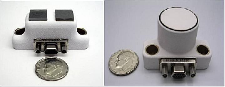
- CREDANCE (Cosmic Radiation Environment Dosimetry and Charging Experiment) is SET’s space weather monitor, built to survey cosmic rays and particles in the radiation belts. These are the high-energy fragments of atoms that can pierce the walls of spacecraft, damaging electronics.
- Two circuit board experiments also study single event effects. COTS-2 (Commercial Off the Shelf-2) collects information on the frequency of single event effects and how to mitigate them, especially in specialized computer chips. DIME (Dosimetry Intercomparison and Miniaturization Experiment) — consists of two separate boards that together demonstrate six different ways to measure space radiation using affordable, commercially available parts. The experiment can help future missions decide the best way to monitor radiation for their spacecraft.
- Another circuit board experiment focuses on total radiation dose. ELDRS (Enhanced Low Dose Rate Sensitivity) is named for the mystery it studies: the ELDRS effect. This is what engineers call the intensified damage that certain types of electronics face when exposed to mild radiation over time — as opposed to the lesser damage experienced if exposed to the same total dose all at once. Information from this experiment will help improve test methods on Earth to make electronics space-ready.
- Together, the SET experiments will expand our understanding of the near-Earth space environment and how its radiation impacts instruments. “SET data will directly go into improving our models so we can better evaluate the radiation environment future missions will encounter,” said Goddard aerospace engineer Megan Casey. Models are a key component in selecting and testing any electronics destined for spaceflight.
- SET is part of the SFx (Space Environment Effects) experiment, one of three experiments on board the DSX (Demonstration and Science Experiments) spacecraft being launched by the U.S. Air Force.
- DSX is launching as part of the STP-2 (Space Test Program-2) mission, managed by the U.S. Air Force Space and Missile Systems Center (SMC). SET is one of four NASA missions on this STP-2 launch — all of which are dedicated to improving technology in space. DSX separates from the launch vehicle approximately 3.5 hours after launch.
• December 12, 2012: The USAF have awarded SpaceX with two Evolved Expendable Launch Vehicle (EELV)-class missions to ride on their Falcon 9 and Falcon Heavy rockets in 2014 and 2015 respectively. The launches, which fall under OSP-3 (Orbital/Suborbital Program-3), will mark SpaceX’s debut for this class of mission. 19)
• May 2009: The DSX spacecraft was delivered to AFRL in May, 2009, and SNC has provided engineering support to AFRL’s AI&T activities since that time. DSX is presently awaiting launch, expected in 2015. 20)
Launch
DSX is a secondary payload on the STP-2 rideshare mission of USAF, launched on 25 June 2019 (06:30 UTC) aboard a SpaceX Falcon Heavy launch vehicle from Launch Complex 39A at NASA’s Kennedy Space Center. The STP-2 payload includes six FormoSat-7/COSMIC-2 satellites (primary payload, each with a mass of 280 kg), developed by NOAA and Taiwan’s National Space Organization to collect GPS radio occultation data for weather forecasting. The mission also carries several NASA technology demonstrations. The STP-2 mission is led by the Air Force Space Command’s Space and Missile Systems Center (SMC). The total IPS (Integrated Payload Stack) has a mass of 3700 kg. 21) 22)
Secondary Payloads
The secondary payloads on this flight are:
• DSX (Demonstration and Science Experiments) mission of AFRL
• GPIM (Green Propellant Infusion Mission), a demonstration minisatellite of NASA (~180 kg). 23)
• FalconSat-7, a 3U CubeSat mission developed by the Cadets of the U.S. Air Force Academy (USAFA) at Colorado Springs, CO.
• NPSat-1 (Naval Postgraduate School Satellite-1) of the Naval Postgraduate School, Monterey, CA. A microsatellite of 86 kg.
• OCULUS-ASR (OCULUS-Attitude and Shape Recognition), a microsatellite (70 kg) of MTU (Michigan Technological University), Houghton, MI, USA.
• Prox-1, a microsatellite (71 kg) of SSDL (Space Systems Design Laboratory) at Georgia Tech.
• LightSail-2 of the Planetary Society, a nanosatellite (3U CubeSat, 5 kg) will be deployed from the parent satellite Prox-1.
• ARMADILLO of UTA (University of Texas at Austin), a nanosatellite (3U CubeSat) of ~ 4 kg.
• E-TBEx (Enhanced Tandem Beacon Experiment), a tandem pair (3U CubeSats) of SRI International.
• TEPCE (Tether Electrodynamics Propulsion CubeSat Experiment), a 3U CubeSat (3 kg) of NPS (Naval Postgraduate School).
• CP-9 , a joint CP-9/StangSat experiment, which is a collaboration between PolySat at Cal Poly and the Merritt Island High School, and is sponsored by the NASA LSP (Launch Services Program). CP-9 is a 2U CubeSat while StangSat is a 1U CubeSat.
• PSat-2 (ParkinsonSAT), a student built 1.5U CubeSat of USNA (US Naval Academy) with a mass of 2 kg.
• OTB-1 (Orbital Test Bed-1) a minisatellite of SSTL (based on the SSTL-150 bus, 138 kg). One of the hosted payloads is NASA's DSAC (Deep Space Atomic Clock), a technology demonstration mission with the goal to validate a miniaturized, ultra-precise mercury-ion atomic clock that is 100 times more stable than today’s best navigation clocks.
Orbits
The STP-2 mission will be among the most challenging launches in SpaceX history with four separate upper-stage engine burns, three separate deployment orbits, a final propulsive passivation maneuver and a total mission duration of over six hours. It will demonstrate the capabilities of the Falcon Heavy launch vehicle and provide critical data supporting certification for future National Security Space Launch (NSSL) missions. In addition, [the USAF] will use this mission as a pathfinder for the [military’s systematic utilization of flight-proven] launch vehicle boosters.
The three orbits of the STP-2 mission for spacecraft deployment are:
1) The small secondary CubeSat satellites will be deployed into an elliptical orbit of ~300 x 860 km, inclination of ~28º. These are: OCULUS-ASR, TEPCE, E-TBEx, FalconSat-7, ARMADILLO, PSAT-2, BRICSAT, and CP-9/StangSat.
2) The second deployment batch of the STP-2 mission will occur at a circular altitude of 720 km and an inclination of 24º.
- Deployment of LightSail-2, Prox-1, and NPSat-1
- Deployment of OTB-1 with NASA's DSAC and GPIM
- The six FormoSat-7/COSMIC-2 satellites will be deployed next into an initial circular parking orbit of 720 km. Eventually, they will be positioned in a low inclination orbit at a nominal altitude of ~520-550 km with an inclination of 24º (using their propulsion system). Through constellation deployment, they will be placed into 6 orbital planes with 60º separation.
3) The third and final deployment will be the Air Force Research Lab's DSX spacecraft as well as the ballast, which will be delivered to an elliptical MEO (Medium Earth Orbit) with a perigee of 6000 km and an apogee of 12000 km, inclination of 43º.
At 10:04 UTC, more than three-and-a-half hours after liftoff, the Falcon Heavy deployed the mission’s final payload — the Air Force Research Laboratory’s DSX (Demonstration and Science Experiments) spacecraft (Ref. 21).
This orbit will permit DSX to fly through the outer region of the inner Van Allen radiation belt, the slot region, and the inner region of the outer Van Allen radiation belt. The total ionizing dose (TID) for the mission is estimated to be equivalent to 10 krad/year behind 8 mm of aluminum shielding. The implication of this is that all DSX equipment must be designed to survive the radiation environment, through the use of shielding, selection of radiation and SEU (Single Event Upset) tolerant or hardened components, or a combination of these approaches.
Mission Status
• October 05, 2021: Fifty scientists from Department of Defense laboratories, industry and research universities met virtually September 22 – 23, to discuss the initial findings from the Air Force Research Laboratory’s Demonstration and Science Experiments (DSX) spacecraft that completed a 23-month mission in May 2021. 24)
- The Air Force Research Laboratory’s Space Vehicles Directorate located on Kirtland AFB, hosted the meeting that included scientific presentations and discussion surrounding the more than 1,200 experiments DSX conducted. Joining AFRL were scientists from MIT-Lincoln Laboratory, the Univ. of Massachusetts-Lowell, Stanford Univ., NASA, Montana State Univ., Atmospheric and Environmental Research Inc. and Leidos.
- The unique spacecraft, envisioned, built and tested entirely in house at Kirtland AFB, was launched June 25, 2019 with the goal to explore the complex relationship between very low frequency radio waves and the Earth’s radiation belts in medium Earth orbit (MEO).
- “We welcome the great minds that have come together to synthesize the results of the DSX satellite experiment,” said Col. Eric Felt, the director of the Space Vehicles Directorate, in his keynote address to the meeting attendees. “The science work isn’t done until it is written down and analyzed so that it will be available for future generations.”
- “This meeting was in part, the AFRL science team’s thought process to make sense of the hundreds of experiments – to build a comprehensive picture, to explain the unexpected and to move us further in applying our results to benefit DoD missions,” said Dr. William Robert Johnston, senior research physicist and DSX principal investigator. “We saw many phenomena, some expected and some unexpected.”
- DSX was many years in the making as scientists studied how to operate spacecraft in the harsh radiation environment of the Van Allen radiation belts and to develop technologies to protect low Earth orbiting (LEO) satellites from the effects of HANE (High Altitude Nuclear Explosions).
- The threat of HANE has been around since the late 1950’s, when high altitude nuclear tests demonstrated wide-area effects with significant military impact for numerous systems.
- “High altitude nuclear explosions have an impact on radar, communications, optical sensors, satellites, electronics and power, to name a few, and a modern HANE would devastate military, national, and commercial LEO satellites,” said Erin Pettyjohn, who gave opening remarks and leads the directorate’s Geospace Technologies Division.
- Pettyjohn further elaborated that analyzing the DSX science data will help in developing technologies to mitigate the effects of HANE on spacecraft.
- “A high altitude nuclear explosion can produce a long-lasting artificial radiation belt far more damaging to orbiting spacecraft than the natural belts,” Johnston said. “Our primary mission for DSX was to test performance of an antenna in space for transmitting radio waves that would wash out such an artificial radiation belt.”
- This was only one of the many types of studies DSX carried out, with a variety of applications for the DoD. Other DSX missions included gathering data on the radiation environment in medium Earth orbit to improve design of satellites for this region, and testing of methods to control the orientation of very large structures in space.
- Looking to the future, the AFRL team will continue analysis of the results, and in the coming months some of those will be published and presented to the broad scientific community.
- “Apart from the applications for DoD, the wealth of basic scientific results gathered from this unique mission will benefit ongoing research into radiation belt dynamics and other issues of design for the space environment,” Johnston explained. “Since DSX’s orbit took it to regions not frequently visited, our observations will help scientific understanding of these dynamics and be of general benefit to civilian space operations as well.”
- Felt complimented the team on the success of the DSX mission and the great work they have done for the nation.
- “The last thing we want is a war with an adversary in space,” Felt said. “Having a robust lab creates uncertainty of our capabilities and keeps our adversaries guessing, providing important deterrence.”
• July 19, 2021: The U.S. Air Force Research Laboratory announced July 19 it has completed a two-year experiment that will help better understand the effects of radiation on space hardware in medium Earth orbit. 25)
- Known as the Demonstration and Science Experiments (DSX) mission, the spacecraft was one of 24 payloads launched June 25, 2019, on a SpaceX Falcon Heavy rideshare.
- AFRL had spent 16 years developing and testing DSX. The mission was to study the harsh radiation environment of MEOs (Medium Earth Orbits) — from about 2,000 to 35,000 kilometers above Earth — where the Defense Department operates critical spacecraft like the Global Positioning System.
- DSX was designed and built at AFRL’s Space Vehicles Directorate at Kirtland Air Force Base, New Mexico. Once deployed, DSX unfolded into a large structure spanning nearly the length of a football field.
- Robert Johnston, AFRL’s lead science investigator, said DSX was the largest unmanned self-supporting structure ever put into orbit.
- “We completed more than 1,300 experiments,” said Johnston. “AFRL engineers and scientists will be analyzing the remarkable amount of data collected from the experiment for many years to come.”
- The DSX mission ended May 31. AFRL engineer Rachel Delaney said the satellite was passivated, but was not deorbited.
- Spacecraft in higher orbits go through a passivation process to lower the likelihood of creating space debris or interfering with operating spacecraft. They maneuver to a “disposal orbit” that’s not used by operating spacecraft. They are commanded to deplete any remaining propellant, turn off their transmitters, deplete their batteries and turn off any capability to recharge them to ensure they don’t explode or become a danger to the other objects in space.
- “Because DSX was in a higher orbit not commonly used by spacecraft, it was not deorbited,” Delaney told SpaceNews. “Instead, commands were sent to render the spacecraft inoperable so it would not pose a risk to other operational satellites in the future.”
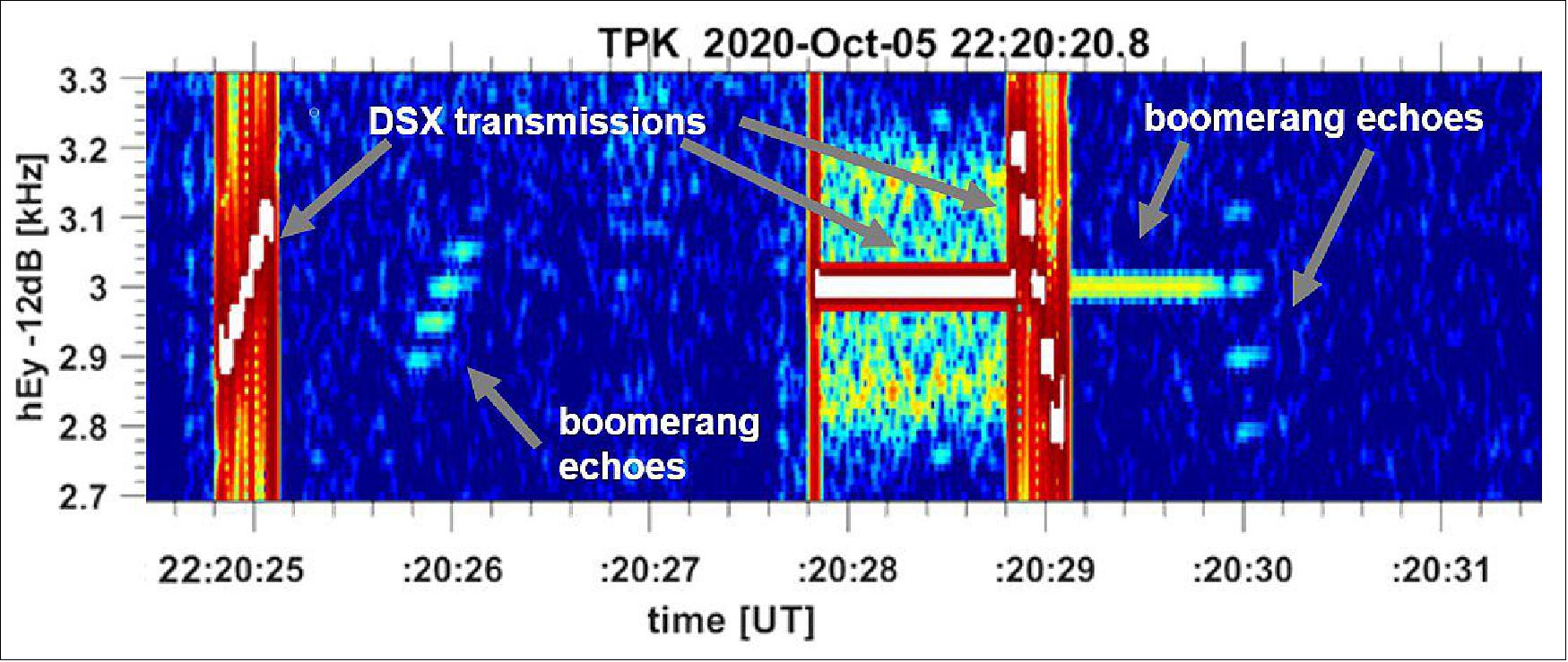
• May 14, 2020: The Air Force Research Laboratory’s (AFRL) Demonstration and Science Experiments (DSX) spacecraft continues its scientific investigations despite the COVID-19 pandemic that has impacted every aspect of life around the world. 26)
- DSX launched into a 6000 km by 12000 km orbit on June 25, 2019 aboard a SpaceX Falcon Heavy as part of the STP-2 mission sponsored by the DoD Space Test Program, with the primary mission to uncover the complex relationship between very low frequency (VLF) radio waves and the Earth’s radiation belts.
- “DSX has been actively transmitting a variety of VLF signals to understand the performance of our transmitter and antenna,” says DSX Principal Investigator Dr. James McCollough. “We are very pleased with the quality of the payloads, and have been collecting a treasure trove of environmental measurements as well.”
- DSX was joined on orbit in February 2020 by the Very Low Frequency Propagation Mapper (VPM), an AFRL-built small satellite (6U CubeSat, mass of 8 kg) designed to listen to radio transmissions from its larger sibling at large distances as it actively probes the response of radiation belt electrons to weak radio waves.
Note: VPM was launched on 5 December 2019 on the Dragon CRS-19 mission to the ISS. On 30 January 2020, the VPM CubeSat was flown on Cygnus into a higher orbit and deployed in early February 2020 — trying to listen for DSX's signals in about two to four weeks after deployment.
- “Both missions have been performing well,” says Lt. Col. James Caldwell, Mission Director for both DSX and VPM. “We are very proud of our AFRL space experiment team for achieving several firsts on these missions. Our operations teams have found ways to safely navigate the unprecedented challenges posed during the pandemic.”
- In addition to studying the dynamics of the Earth’s natural radiation belts, the two satellites are developing technologies to protect low earth orbiting spacecraft from the effects of high-altitude nuclear explosions.
- “We learned in the late 50’s and early 60’s that putting a warhead on a missile and detonating it in space produces a long-lived, extremely intense belt of radiation in low earth orbit,” explains Dr. Michael Starks, who leads AFRL’s Radiation Belt Remediation (RBR) effort. “This radiation is deadly to unprotected satellites and an explosion in today’s on-orbit environment, intentional or otherwise, could cause grave damage to spacecraft that pass through it. We have been working for 15 years to develop technologies to harmlessly eliminate that radiation before it can wreak havoc.”
- The DSX spacecraft is designed to test the performance of a space-based antenna at injecting radio waves that effectively wash out the nuclear radiation belts. Of course, there aren’t currently any nuclear belts to subject to the experiment, but the Earth’s natural radiation belts operate in the same way.
- “DSX isn’t powerful enough to cause a significant change to the natural belts,” Dr. McCollough says. “But it does help validate our calculations of how an actual radiation belt remediation capability would perform.”
- The DSX and VPM spacecraft are anticipated to continue their tandem experiment for about another six months.
- “This is a great example of AFRL putting our deep expertise to work on long-standing difficult problems,” says Col. Eric Felt, Director of AFRL’s Space Vehicles Directorate. “This has been a long road for the RBR / DSX / VPM team. I’m excited to see their hard work and perseverance deliver a game-changing capability to our nation.”
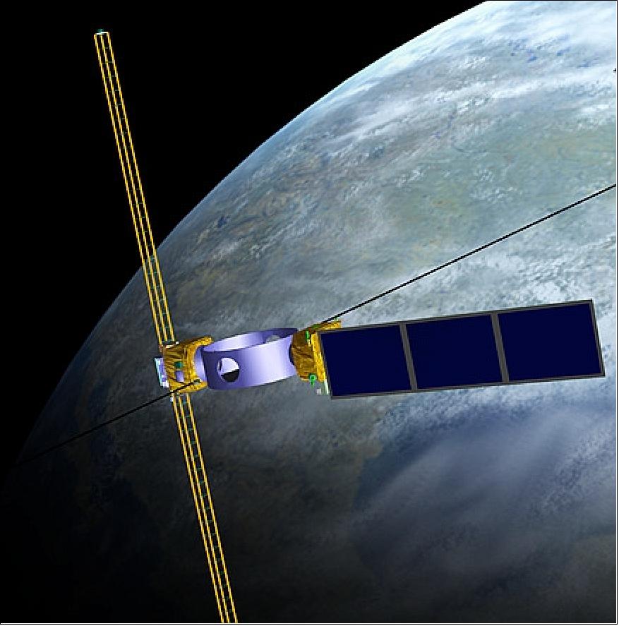
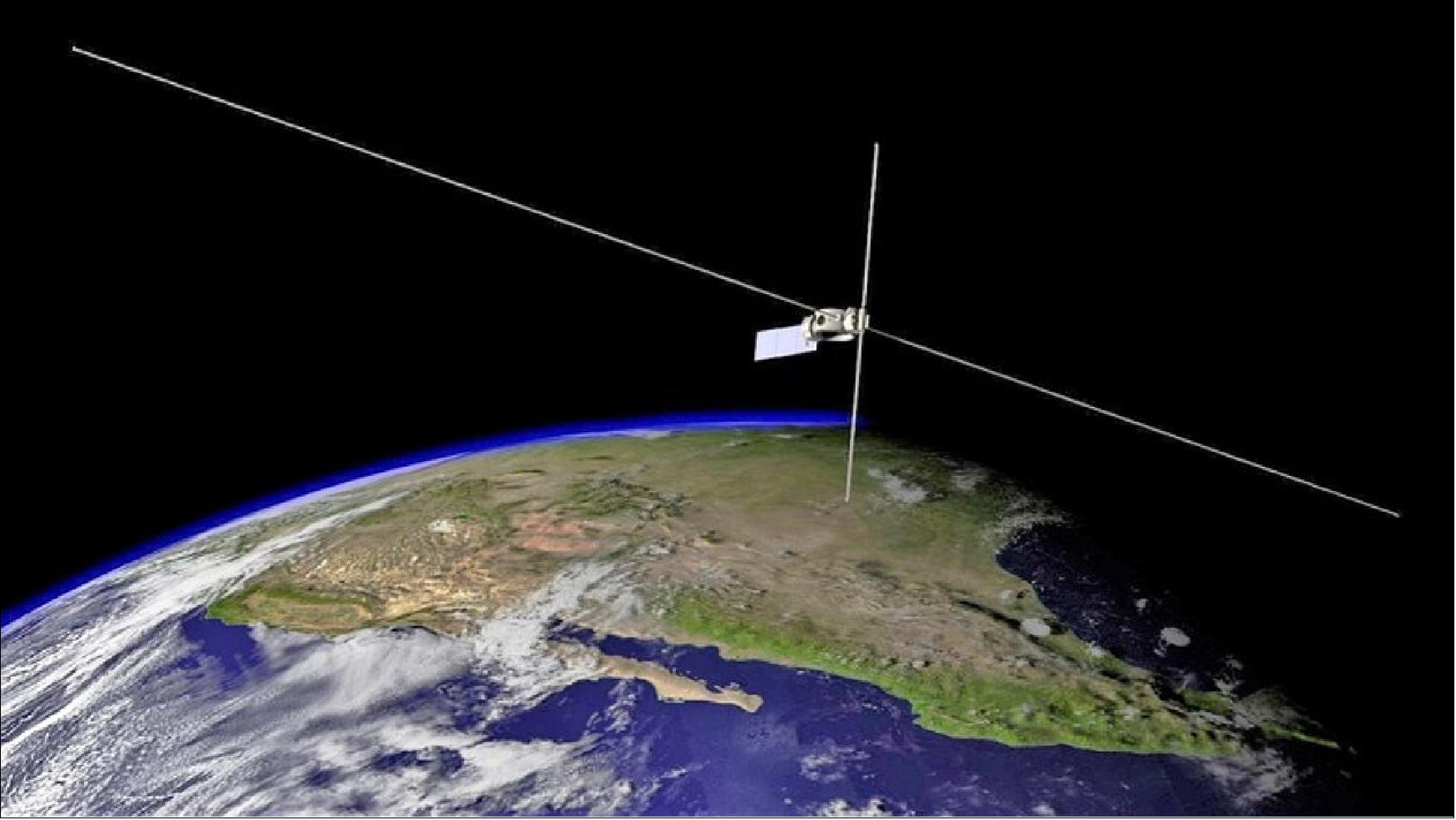
• July 31,2019: A satellite spanning nearly the length of a football field was launched on board a SpaceX Falcon Heavy rocket from Cape Canaveral, Fla., June 25. 27) 28)
- Described by Elon Musk as the "toughest rocket launch ever," SpaceX delivered 24 experimental satellites into four different orbits, of which the Air Force Research Laboratory's DSX (Demonstration and Science Experiments) spacecraft was the largest. The first of its kind, DSX was designed and built at the AFRL (Air Force Research Laboratory) at Kirtland AFB.
- "The satellite is conducting new research to advance understanding of the Van Allen radiation belts and their effect on spacecraft components, and valuable information is already being received," said Col. Eric Felt, AFRL Space Vehicles Directorate director. "We expect DSX to conduct on-orbit experiments for at least a year."
- "The Air Force is interested in operating satellites in the region where DSX is collecting data. This will allow us to better understand the environment through its various experiments," said Dr. James McCollough, DSX principal investigator.
- "This is a region where Very Low Frequency (VLF) radio waves strongly interact with electrons that are hazardous to spacecraft. A particularly exciting aspect of DSX is the ability to actively transmit VLF signals to study their influence on the electron population in a completely new way. This will allow a more thorough understanding of a key process governing the radiation environment."
- The satellite is currently in "Launch and Early Operations" where the operations team works with DSX scientists and engineers to perform checkouts on various satellite components, deploy the antenna booms, and prepare for data collection within the Van Allen radiation belts, said Lt. Col. James Caldwell, DSX mission director.
- On July 12, the longer pair of the antenna booms (80 meters tip-to-tip) was successfully deployed as the largest unmanned structure ever in space. Jeffrey Christmas, DSX program manager, explained that the exceptionally long length of this antenna allows DSX to transmit the VLF radio waves used for planned experiments based on the longer wavelengths of these frequencies (see video of Figure 5).
- Throughout the coming months, researchers at AFRL will be sharing their findings with the public, through its website and social media platforms. "We know there are many out there who will be interested to see the data as it comes in," said Felt.
- The DSX program is led by the AFRL Space Vehicles Directorate at Kirtland AFB, New Mexico, with key team members from the Air Force Space and Missile Systems Center also located at Kirtland Air Force Base.
Sensor Complement (WPIx, SWx, SFx)
DSX has thirteen payloads arranged into three main groups of experiments: WPIx, SWx, and SFx.
WPIx (Wave Particle Interaction Experiment)
The WPIx experiment package is designed to measure critical parameters for space and ground-based wave particle interactions: efficiency of VLF injection, propagation, and efficacy. The mission objectives for WPIx are to:
1) Determine VLF injection efficiency from a space-based antenna.
2) Map VLF fields from geophysical and man-made sources
3) Measure precipitating particles scattered by VLF from geophysical, ground-based transmitter, and DSX VLF transmitter sources.
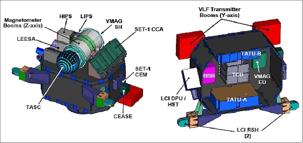
The WPIx experiment consists of the following payloads: BBR (Broadband Receiver), TATUs (Transmitter and Tuning Units), TCU (Transmitter Control Unit) including the NBR (Narrowband Receiver), TASC (Tri-Axial Search Coil), VMAG (Vector Magnetometer), ECS (Experiment Computer System), LCI (Loss Cone Imager), Y antenna, and Z antenna.
VLF (Very Low Frequency Receiver)
The VLF broadband receiver is comprised of the BBR, TASC, Y antenna, and Z antenna. The VLF receiver has three search coil magnetometers (3 B [magnetic] components via TASC), two linear, orthogonal dipole antennas with 2 E (electric) components. The frequency range is 100 – 50 kHz and the sensitivity is 1.0 e-16 V2 m-2 Hz-1 (E) and 1.0 x e-11 nT2 Hz-1 (B). The VLF receiver is built by Stanford University, NASA/GSFC, Lockheed Martin, and ATK.
The VLF narrowband receiver is comprised of the NBR and the Y antenna, covering the band from 3 kHz to 750 kHz. The VLF transmitter operates in two modes, high power (i.e. Whistler mode waves) at 3 – 50 kHz at up to 500 W (900 W at end of life), and low power mode (i.e. Boomerang mode waves) at 50 – 750 kHz at 1 W, and the local electron density. The transmitter is built by the University of Massachusetts Lowell (UML), SwRI (Southwest Research Institute), and ATK.
The LCI (Loss Cone Imager) features a HST (High Sensitivity Telescope) which will measure 100 – 500 keV electrons with 0.1 cm2 str geometric factor with 6.5º of loss cone. The LCI also features a FSH (Fixed Sensor Head) with 130º x 10º of pitch angle distribution for 50 – 700 keV electrons every 167 ms. Boston University is building the LCI instrument. 29) 30)
Finally, the VMAG (Vector Fluxgate Magnetometer) instrument is capable of 0 – 8 Hz three axis measurements at ± 0.1 nT accuracy of magnetic field line measurements. The VMAG is built by the University of California Los Angeles (UCLA). 31)
MAG is being used to determine the direction of the magnetic field to better than 1º at all points in the orbit. This performance will allow the mapping of locally measured particle distributions to global distributions. VMAG sensors will measure the DC magnetic field over a 100-10000 nT range with ±0.1 nT accuracy at 20 Hz. VMAG will operate continuously to provide DC magnetic field and ULF wave environment data required by the Space Weather Experiment MEO space particle modeling experiment. Hence, it supports the experiment objectives of both the WPIx and the SWx.
The VMAG electronics will be mounted within the payload module and the fluxgate sensor will be deployed on the tip of the -Z boom, opposite TASC.
VLF Transmitter
The VLF transmitter on DSX provides the capability to conduct active experiments to quantify spaceborne VLF wave-injection efficiency and determine the details of the wave-particle interactions. An electron loss cone detector on DSX allows direct correlation of changes in energetic particle distributions with injected wave power. The objective is to develop and verify accurate models of the VLF injection, propagation, and wave particle interaction processes with DSX data.
The VLF antennas are aligned normal to the local magnetic field line when spacecraft is within ±20º of equatorial (i.e., when VLF propagation experiments and measurements will be performed). Pointing requirements are fairly relaxed with a 2º control and a 1º knowledge requirements deemed to be sufficient.
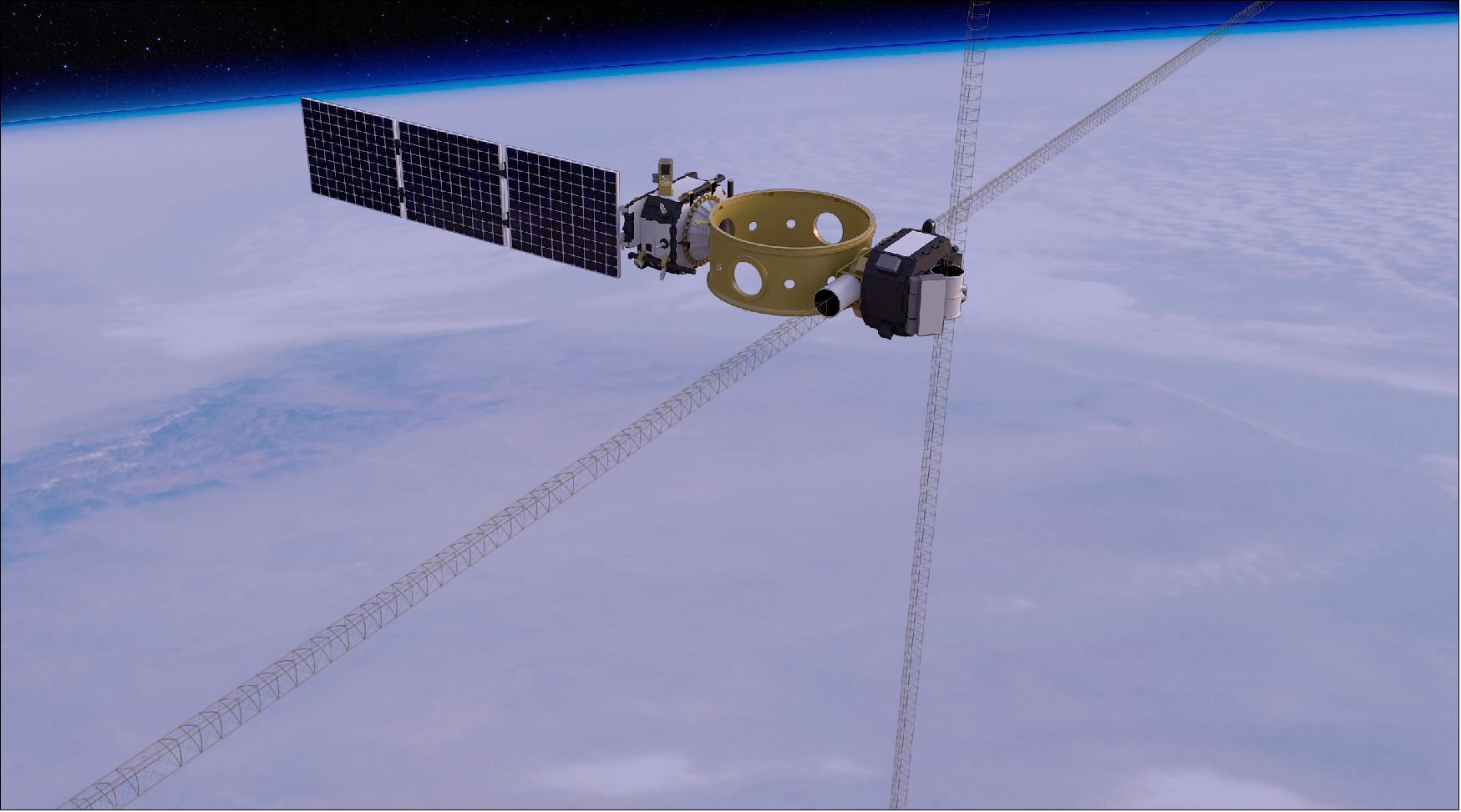
The design of the transmitter was driven by objectives 1 and 2, but also influenced by the desire to maximize space flight heritage to minimize risk, and budget constraints. The DSX Y antenna is 80 m in length (tip-to-tip) and functions as a VLF receive and transmit antenna. The DSX Z antenna is 16 m in length (tip-to-tip) and functions as a VLF receive antenna in a cross-dipole configuration with the Y antenna. The TASC and VMAG instruments are placed at opposite tips of the Z antenna to separate them from the rest of the DSX instruments and their electrical and mechanical “noise” which would interfere with their operation as VMAG measures the local magnetic field and TASC measures the local electric field.
The antenna lengths were based on the general opinion among space physicists that the longer and wider the antenna the better due to minimizing impedance when generating VLF waves in a magnetized plasma.
The transmitter voltage design is based on NASA’s IMAGE (Imager for Magnetopause-to-Aurora Global Exploration) RPI (Radio Plasma Imager) instrument built by UML that operated at 3 kV and was optimized for > 50 kHz. The DSX design optimizes the transmitter impedance dependant on frequency, antenna length, and diameter. DSX is flying the first ever VLF “dynamic tuning” technology to adjust circuit parameters in real time. The voltages are limited to < 10 kV due to critical component limits. The DSX system is nominally designed for 5 kV with the capability to go to 10 kV at the end of life (EOL).
SWx (Space Weather Experiment)
The objective of the Space Weather Experiments (SWx) are to measure, map, and characterize the space weather environment in the slot region for electrons, protons, ions, and plasma and then develop and validate models of this region. The SWx payloads are as follows: 32)
• CEASE (Compact Environmental Anomaly Sensor)developed by Amptek Inc.. CEASE will measure radiation dose, dose rate, surface dielectric charging, deep dielectric charging, and single event effects. The device was flown on TSX-5 (launch June 7, 2000), on STRV-1C (launch Nov. 16, 2000), and on DSP-21 [(Defense Support Program-21) satellite, launch Aug. 6, 2001]. CEASE consists of two dosimeters, two particle telescopes, and a SEE (Single Event Effect) detector. The device has the capability to monitor a broad range of space hazards from surface damage and charging (keV electrons) to SEE events resulting from >100 MeV cosmic rays and solar protons. The angular FOV for CEASE is relatively large and will not resolve pitch-angle distribution. CEASE will be mounted on an exterior panel of the payload module. One change for DSX is that CEASE will capture and downlink the full dose spectra from each dosimeter, whereas prior versions only captured six reduced data points (two for low LET data and four for high LET data). 33)
• HEPS (High Energy Proton Spectrometer), developed by Amptek Inc. The objective is to measure protons with energies between 15 and 440 MeV and electrons with energies between 1.5 and 20 MeV. These high energy particles are responsible for microelectronics damage, displacement and total dose damage, SEEs, and deep dielectric charging. HEPS will be mounted on the AM battery enable bracket.
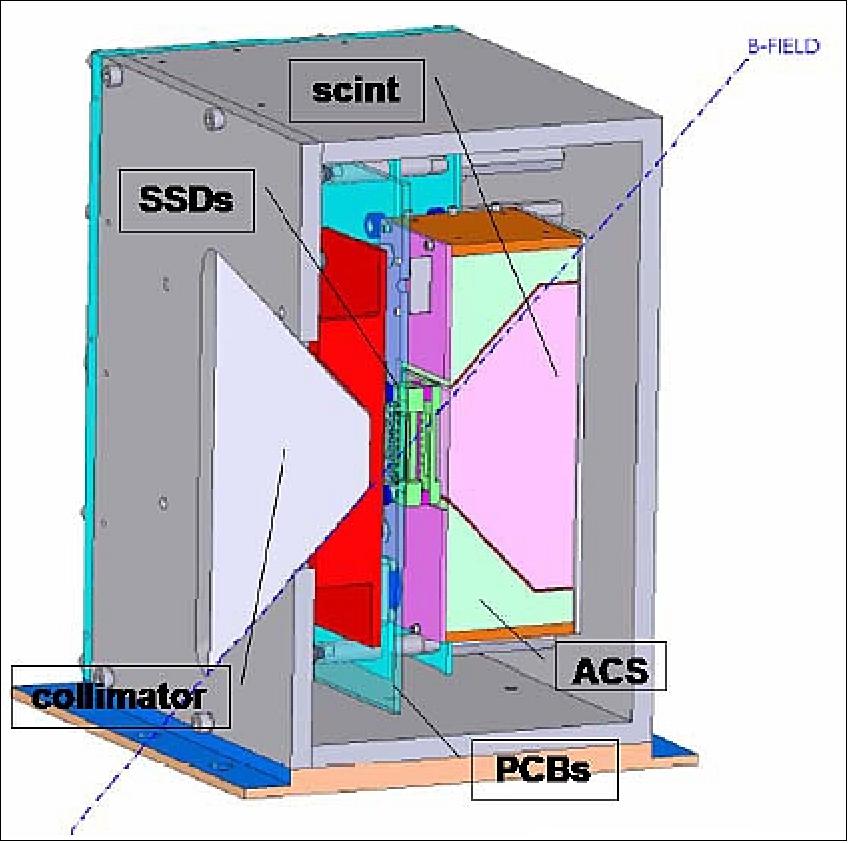
• LIPS (Low Energy Imaging Proton Spectrometer), developed by PSI. The objective is to measure the ring current particles that are important in the energy flow processes in the magnetosphere. This particle population plays an important role in spacecraft charging and surface damage due to sputtering. The instrument uses specially designed combinations of scintillator materials to detect electrons and protons with energies between 30 keV and 2 MeV. Eight 10º x 8º apertures will provide pitch angle resolution. LIPS will be mounted on an exterior panel of the payload module.
• LESSA (Low Energy Electrostatic Analyzer), developed by Amptek Inc. The objective is to measure energy fluxes and energy spectra for low-energy electrons and protons (100 eV to 50 keV). These low energy particles are responsible for surface electric charging and damage to thin films such as thin-film photovoltaics, conventional solar cell cover glasses, and coatings. LEESA will be mounted on an exterior panel of the avionics module.
• HIPS (High Energy Imaging Proton Spectrometer), developed by PSI (Physical Sciences Inc.). The objective is to measure electrons with energies between 1-10 MeV and protons with energies between 30 and 300 MeV. These high-energy particles are responsible for microelectronics damage, displacement and total dose damage, SEEs, and deep dielectric charging. HIPS will be mounted on an exterior panel of the payload module.
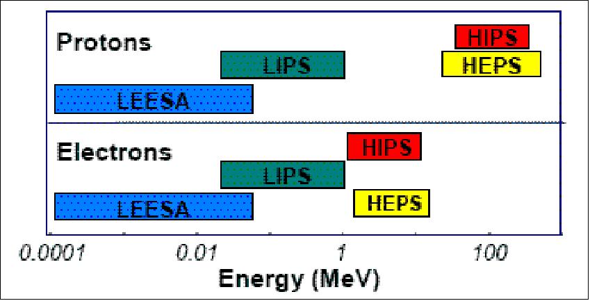
DSX will be flying the most comprehensive particle energy coverage ever in MEO. The benefits of the SWx experiment are that electron and proton detectors measure both the spectral content and angle-of-arrival of both species over broad energy ranges. Also, the DSX sensor suite will help correct deficiencies in the current standard radiation-belt models of the inner magnetosphere by providing:
- Spectrally resolved, uncontaminated measurements of high energy protons (10-400 MeV) and electrons (1-30 MeV).
- Accurate mid-to-low energy (< 1000 keV) measurements of the energetic particle and plasma environment.
- Transformation of angle-of-arrival measurements into estimates of the flux distribution with respect to the local pitch-angle (via on-board magnetometers).
SFx (Space Environmental Effects Experiments)
SFx consist of the NASA Space Environment Testbeds-1 (SET-1) and the Air Force Research Laboratory; Propulsion Directorate (AFRL/RZ) produced radiometers and photometers. The objectives of SET-1 are to improve engineering approaches to accommodate and/or mitigate the effect of solar variability on spacecraft design and operations, reduce risk for new technologies infused into future space missions, and provide a standard mechanical, electrical, and thermal interface for a collection of small flight investigations. 34) 35)
The SET-1 payload is comprised of two units, CEM (Correlative Environment Monitor) and CCA (Central Carrier Assembly). The carrier provides a single interface for power and data between the DSX spacecraft and the SET-1 microelectronic investigations (inside the CCA) and CEM.
The CCA houses five sub-experiments:
• CREDANCE (Cosmic Radiation Environment Dosimetry and Charging Experiment)
• DIME-1 (Dosimetry Inter-comparison and Miniaturization Experiment Board #1)
• DIME-2 (Dosimetry Inter-comparison and Miniaturization Experiment Board #2)
• ELDRS (Linear Enhanced Low Dose Rate Sensitivity)
• COTS-2 (Commercial Off the Shelf Technology)
The SET-1 project is part of the LWS (Living With a Star) program managed at NASA/GSFC. The LWS program and the SET -1 project are sponsored by the Science Mission Directorate of NASA/HQ.
The objective of the photometers and radiometers (Figure 15) is to measure changes in optical transmission, thermal absorption and emission due to the MEO radiation environment. Coupon level testing of specific developmental coatings intended for thin-film photovoltaics will be performed using these sensors. The radiometers will detect changes in thermal control paint coefficients of heat gain / loss based on exposure and the photometers will measure the effects of erosion from quartz windows and re-deposition of material onto nearby optics.
Technology
Modular spacecraft integration concept: DSX maximizes the benefits of modular integration via an architecture which requires that all devices adhere to a standard interface for control and communications (electrical, power, command & communications protocol). This is enabled by the use of dual-redundant network interface cards in the ECS (Experiment Computer System) chassis that provide for command and data interface between the flight control computer and all payloads. Rather than a single onboard computer responsible for handling all spacecraft functions, DSX unburdens the main spacecraft computer from payload-related operations by providing a dedicated payload-interface computer: the ECS. The highly generalized ECS design, developed by QNA-PSI (Qinetiq-North America-Planning Systems, Inc.), Melbourne, FLA, is capable to handle a wide range of payload types and classes simultaneously, with low data latency. QNA-PCI serves as principal investigator for the attitude control experiment as well as providing the ECS. 36)
In general, the role of the ECS on DSX is required to provide the following functions:
- Isolate the interface complexity associated with 10 distinct payloads from the bus computer both in terms of hardware and command/telemetry
- Provide storage of large amounts (up to 10 GByte) of experiment data and manage the downlink of this data
- Offload the bus computer from intensive computational tasks associated with the ACE (Adaptive Controls Experiment) and payload data processing.
Key operational environmental requirements for the ECS include:
- 1-year mission life
- Tolerance of 100 kRad total ionizing dose in MEO environment
- Emissions and susceptibility per tailored MIL-STD461E
- Operational temperature range of -43ºC to 41ºC.
The ECS is a processor-based command and data handling system consisting of four separate 6U cards on a cPCI backplane. It is capable of 1500 MIPS, while providing 10 GByte of volatile mass storage and 12 distinct serial interfaces. It’s key physical attributes are:
- Total mass: 8 kg
- Peak power: 66W (allocated), 34W (measured @ 30ºC) at 28V.
- Dimensions: 27.5 cm x 20 cm x 17.5 cm.
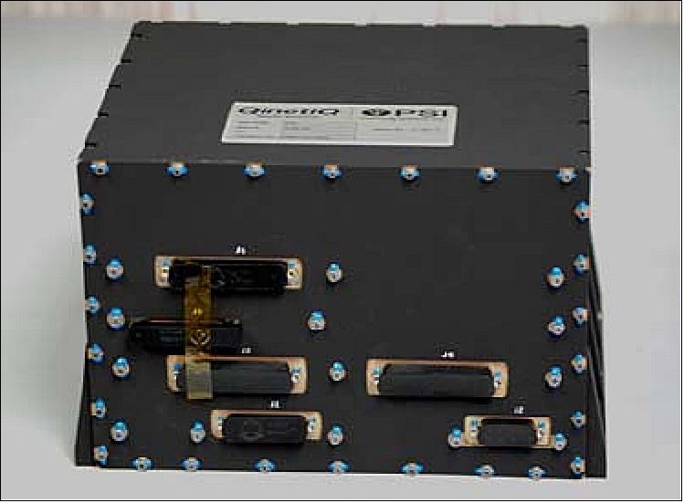
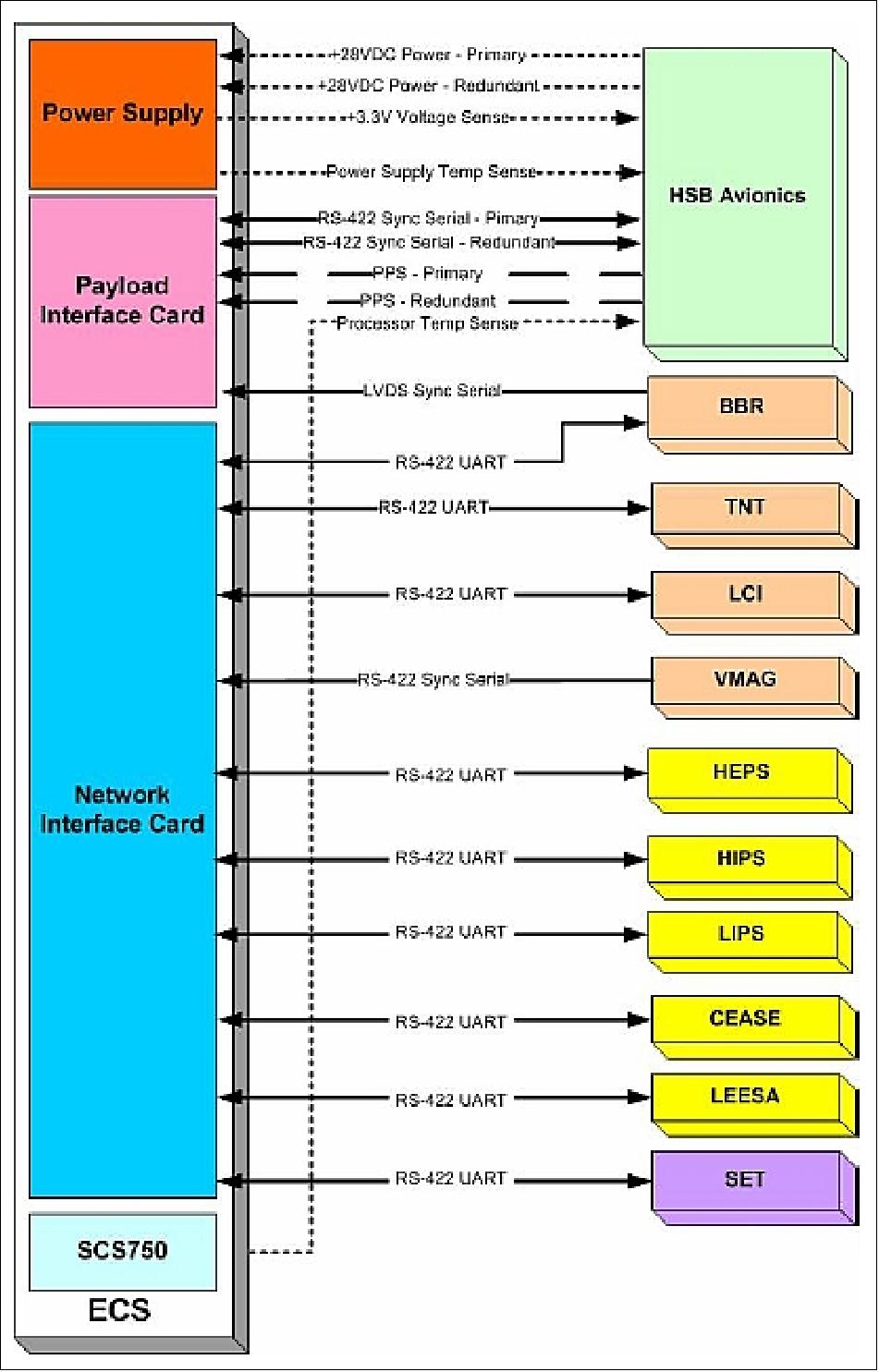
As shown in Figure 20, the four cards within the ECS enclosure consist of a power supply card for conditioning raw 28 V spacecraft power to conditioned supply voltages for ECS components, a single board computer, a serial interface card, and a mass storage card.
The ECS employs the SCS750 single board computer from Maxwell Technologies, running the VxWorks real-time operating system. The SCS750 uses three PowerPC 750FX processors running in a triple-modular redundant configuration to provide 1500 MIPS in the harsh DSX environment with radiation susceptibility equivalent to only 1 uncorrected processor upset every 128 years.
The Network Interface Card (NIC) was purpose built for the ECS application by QNA-PSI. The NIC provides 9 bidirectional and one unidirectional serial ports. All ports use an RS-422 hardware layer. The bidirectional ports use a standard UART (Universal Asynchronous Receiver/Transmitter) protocol with software programmable baud rates ranging from 9600 to 115,200 baud. The unidirectional port uses a clock, data, and enable protocol, with the clock provided by the associated payload to receive data at 40 kbit/s.
The PIC (Payload Interface Card) was designed and built for QNA-PSI by SEAKR Engineering Inc. who also built the power supply card, cPCI backplane, and enclosure. The PIC provides 10 GByte of SDRAM mass storage, available to the processor via dual DMA (Direct Memory Access) channels, as well as an LVDS serial data recording port running at 2 Mbit/s. 37)
The PIC also provides primary and redundant bidirectional RS-422 serial interfaces with the host spacecraft as well as primary and redundant pulse input channels used for synchronizing the ECS timebase with the spacecraft.
CONOPS (Concept of Operations)
There are six separate and distinct mission CONOPS phases: 1) the launch and separation, 2) bus initialization, 3) experiment boom deployment, 4) post-deploy comprehensive checkout, 5) on-orbit experiment operations, and 6) end-of-life (EOL). The potential for residual operations before EOL would be defined as a seventh phase.
Normal operations will be constrained by spacecraft power, data bandwidth and scheduling contacts through the AFSCN (Air Force Satellite Control Network). Therefore payloads will have to be duty cycled. SWx payloads are low impact on resources, basically single modes of operation, and can be turned on early for the duration of the mission with little intervention required. SFx and specifically the SET-1 instrument will have two operating modes that are dependent on solar activity (for S3 storms as detected by CREDANCE) and position in the orbit (triggered by orbit propagator indications of the ascending nodes). Resource demands for SFx are similar to SWx. WPIx is the most demanding on the DSX spacecraft resources, consuming the greatest power (> 650 W peak) and generating the most data (up to 5 GB per orbit).
High power VLF transmission is limited to ±20º latitude about the equatorial plane and to less than 30 minutes. The ACE (Adaptive Controls Experiment) is a secondary experiment and, as its name implies, involves an adaptive controls experiment using the HSB attitude control system interacting with the deployed flexible structures. The only resource requirement for ACE is downlink of data generated from ACE.
Ground Segment
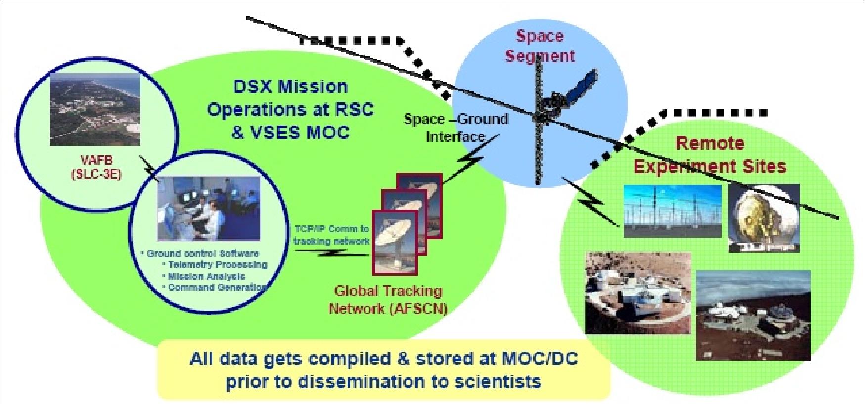
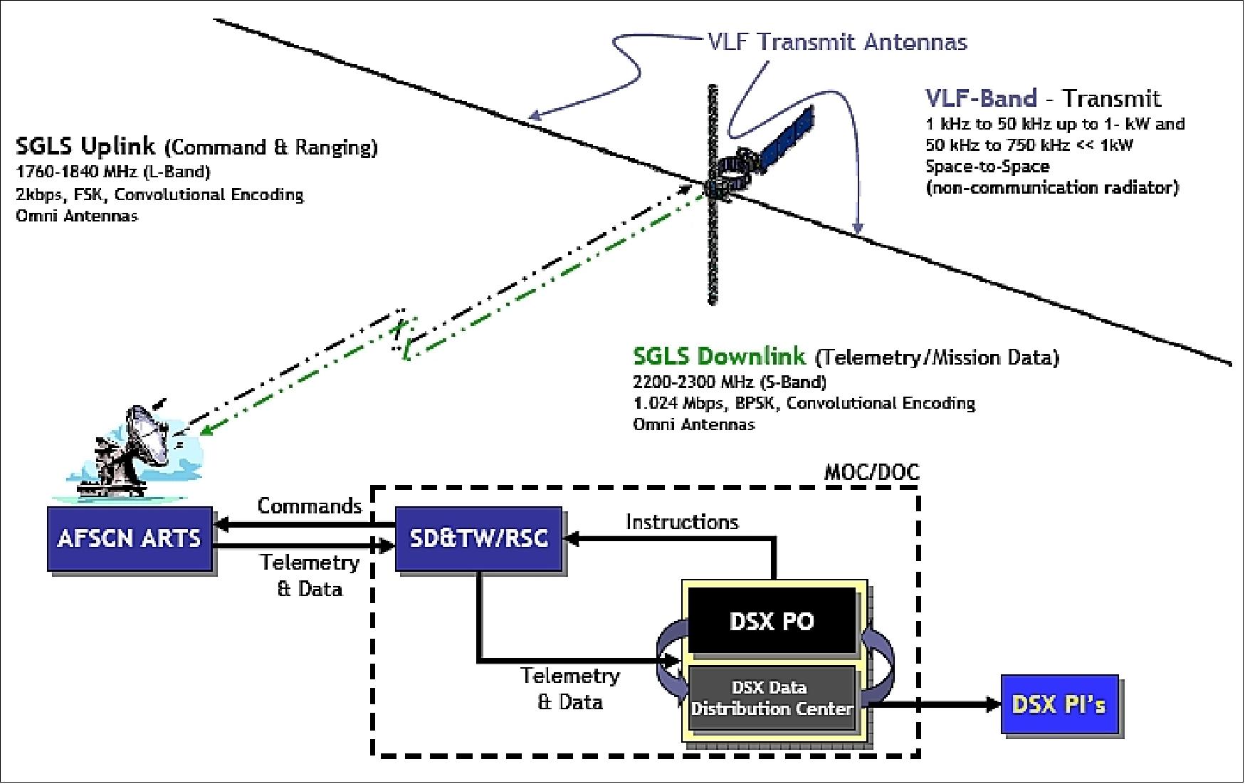
The DSX ground segment consists of three major elements: mission control, global telemetry, tracking, and control (TT&C) network, and the remote experiment sites. The DSX mission will be operated by the MOC/DC (Mission Operations and Data Center) at AFRL. The the MOC/DC is collocated with RSC [RDT&E (Research, Development, Test and Evaluation) Support Complex]. Global data reception/communication is provided by AFSCN (Air Force Satellite Control Network). From the MOC, the flight operations team interfaces with the users, payload and spacecraft equipment manufacturers, remote experiment support sites (optical and radar imaging ranges and VLF ground installations), and RSC operations personnel required to operate the mission. The RSC provides connectivity to AFSCN.
Commands will be sent to the RSC for uplink via the SGLS (Space-Ground Link System) communication protocol to the DSX satellite. Downlinked information from the space vehicle state-of-health will be validated from the real-time operations system located at the RSC. All space-ground links will be accommodated by AFSCN. The DC will collect all DSX data products, conduct analyses, archive data products, and distribute the data products to PIs (Principal Investigators) and users at AFRL and the NASA/POCC (Payload Operations Control Center).
References
1) Mark Scherbarth, Durand Smith, Aaron Adler, Janet Stuart, Greg Ginet, “AFRL's Demonstration and Science Experiments (DSX) Mission,” Amotech 2009 ()Advanced Material On Technology), URL: http://www.amostech.com/TechnicalPapers/2009/Space-Based_Assets/Scherbarth.pdf
2) Mark Scherbarth, Durand Smith, Aaron Adler, Greg Ginet, “AFRL’s Demonstration and Science Experiments (DSX) Mission,” Proceedings of SPIE, Vol. 7438, 'Solar Physics and Space Weather Instrumentation III,'. Ed. Silvano Fineschi & Judy A. Fennelly,. San Diego, CA, USA: SPIE, August 4, 2009 [web source no longer available]
3) Jon Schoenberg, Gregory Ginet, Bronislaw Dichter, Michael Xapsos, Aaron Adler, Mark Scherbarth , Durand Smith, “The Demonstration and Science Experiments (DSX): A Fundamental Science Research Mission Advancing Technologies that enable MEO Spaceflight,” 2006, URL: http://www-ssc.igpp.ucla.edu
/ssc/dsx/DSX-paper.pdf
4) Aaron Adler, Jason Guarnieri, “Overview of the AFRL's Demonstration and Science Experiments (DSX) Program,” Space 2006, Sept. 19-21, 2006, San Jose, CA, USA, paper: AIAA 2006-7509, URL: http://www.dtic.mil/cgi-bin/GetTRDoc?Location=U2&doc=GetTRDoc.pdf&AD=ADA464940
5) Gregory P. Ginet, “Demonstrations & Science Experiment (DSX),” March 5, 2009, URL: http://rbsp.jhuapl.edu/science/meetings/20090304/Ginet_DSX_19Feb2009_v2.ppt
6) Dan Cohen, Joseph Wieber, Jan King, Shane Kemper, Shawn Stephens, Larry Davis, Gregory Spanjers, James Winter, Aaron Adler, Shaun Easley, Martin Tolliver, Jason Guarnieri, “The SSTE-4: DSX Flight Experiment: Design of a Low-Cost, R&D Space Mission with Responsive Enabling Technologies,” Responsive Space Conference 2005, Los Angeles, CA, USA, April 25-28, 2005, paper RS3-2005-3004, URL: https://web.archive.org/web/20060516003116/http://www.responsivespace.com/Papers/RS3/SESSION%20PAPERS/SESSION%203/3004-COHEN/3004P.pdf
7) N. G. Heinsohn, T. Girard, D. Smith, J. Stuart, A. Adler, J. Schoenberg, M. Scherbarth, E. Klaiber, “AFRL's Demonstration and Science Experiments (DSX) Program - Quest for the Common Micro Satellite Bus,” Proceedings of the 21st Annual Conference on Small Satellites, Logan, UT, USA, Aug. 13-16, 2007, SSC07-II-4
8) D. Cohen, J. Schoenberg, G. Ginet, B. Dichter, M. Xapsos, A. Adler, M. Scherbarth, D. Smith, “The Demonstration and Science Experiments (DSX): A Fundamental Science Research Mission Advancing Technologies that enable MEO Spaceflight,” Proceedings of the 4S Symposium: `Small Satellite Systems and Services,' Chia Laguna Sardinia, Italy, Sept. 25-29, 2006, ESA SP-618
9) Greg Spanjers, James Winter, Dan Cohen, Aaron Adler, Jason Guarnieri, Martin Tolliver, Greg Ginet, Bronek Dichter, Jeff Summers, “The AFRL Demonstration and Science Experiments (DSX) for DoD Space Capability in the MEO,” Proceedings of the 2006 IEEE/AIAA Aerospace Conference, Big Sky, MT, USA, March 4-11, 2006
10) Dan Cohen, Ggregory Spanjers, James Winter, Gregory Ginet, Bronik Dichter, Aaron Adler, Martin Tolliver, Jjason Guarnieri, “Design and Systems Engineering of AFRL's Demonstration and Science Experiments,” GATech Space Systems Engineering Conference, Nov. 8-10, 2005, Atlanta, GA, USA, URL: http://smartech.gatech.edu/bitstream/1853/8037/2/SSEC_SD1_doc.pdf
11) J. Winter, G. Spanjers, D. Cohen, A. Adler, S. Kemper, S. Easley, K. Denoyer, M. Tolliver, L. Davis, J. Guarnieri, R. Glover, “Deployable Structures Mission in Medium Earth Orbit.,” Proceedings of the IEEE Aerospace Conference, Big Sky, MT, USA, March 5-12, 2005
12) Jon Schoenberg, Gregory Ginet , Bronislaw Dichter, Michael Xapsos, Aaron Adler, Mark Scherbarth, Durand Smith, “The Demonstration and Science Experiments (DSX): A Fundamental Science Research Mission Advancing Technologies that enable MEO Spaceflight,” 2006, URL: http://www-ssc.igpp.ucla.edu
/ssc/dsx/DSX-paper.pdf
13) “ESPA: The EELV Secondary Payload Adapter,” URL: http://www.moog.com/literature/Space_Defense/Vibration_Control/MCSA_ESPA.pdf
14) http://www.afsbirsttr.com/Publications/Documents/Transition-083110-CSA-AF01-044.pdf
15) “Demonstration and Science Experiments,” SNC, URL: http://www.starsys.com/uploads/brochures/DSX_Satellites.pdf
16) “Flight Proven SN-200,” SNC brochure, URL: URL: http://www.sncspace.com/uploads/brochures/2011/SN-200.pdf
17) ”Air Force Research Laboratory prepares DSX spacecraft for launch,” 88th Air Base Wing Public Affairs, ” 25 June 2019, URL: https://www.af.mil/News/Article-Display/Article/
1886564/air-force-research-laboratory-prepares-dsx-spacecraft-for-launch/
18) ”NASA’s SET Mission to Study Satellite Protection Is Ready for Launch,” NASA, 10 June 2019, URL: https://www.nasa.gov/feature/goddard/2019/
nasa-s-set-mission-to-study-satellite-protection-is-ready-for-launch
19) Chris Bergin, “SpaceX get their foot in the EELV door with double launch contract win,” NASA Spaceflight.com, Dec. 5, 2012, URL: http://www.nasaspaceflight.com/
2012/12/spacex-foot-eelv-door-double-launch-contract-win/
20) http://www.sncspace.com/ss_spacecraft_science.php
21) Stephen Clark, ”Falcon Heavy launches on military-led rideshare mission, boat catches fairing,” Spaceflight Now, 25 June 2019, URL: https://spaceflightnow.com/2019/
06/25/falcon-heavy-launches-on-military-led-rideshare-mission-boat-catches-fairing/
22) ”STP-2 Mission,” SpaceX, URL: https://web.archive.org/web/20190416205015/https://www.spacex.com/stp-2
23) “GPIM Spacecraft to Validate Use of 'Green' Propellant,” NASA, Aug. 19, 2014, URL: http://www.nasa.gov/content/gpim-spacecraft-to-validate-use-of-green-propellant/
24) Jeanne Dailey, ”AFRL presents results from DSX spacecraft experiments,” AFRL News, 05 October 2021, URL: https://www.afrl.af.mil/News/Article/2800402/afrl-presents-results-from-dsx-spacecraft-experiments/
25) Sandra Erwin, ”Air Force satellite completes two-year experiment to study the medium Earth orbit environment,” SpaceNews, 19 July 2021, URL: https://spacenews.com/
air-force-satellite-completes-two-year-experiment-to-study-the-medium-earth-orbit-environment/
26) ”AFRL Satellite Duo Probing Earth’s Radiation Belts,” Kirtland Air Force Base, 14 May 2020, URL: https://www.kirtland.af.mil/News/Article-Display/Article/
2187232/afrl-satellite-duo-probing-earths-radiation-belts/
27) ”AFRL launched largest unmanned space structure on SpaceX Falcon Heavy,” Space Daily, 31 July 2019, URL: http://www.spacedaily.com/reports/
AFRL_launched_largest_unmanned_space_structure_on_SpaceX_Falcon_Heavy_999.html
28) ”AFRL launched largest unmanned space structure on SpaceX Falcon Heavy,” AFRL, 26 July 2019, URL: https://afresearchlab.com/news/
afrl-launched-largest-unmanned-space-structure-on-spacex-falcon-heavy/
29) James D. Sullivan, “DSX loss cone imager differential response functions,” Proceedings of SPIE, Vol. 7438, 'Solar Physics and Space Weather Instrumentation III,'. Ed. Silvano Fineschi & Judy A. Fennelly,. San Diego, CA, USA: SPIE, August 4, 2009
30) David L. Voss, Avi Gunda, Doug Carssow, Theodore Fritz, Anton Mavretic, James Sullivan, “Overview of the loss cone imager fixed sensor head instrument,” Proceedings of SPIE, Vol. 7438, 'Solar Physics and Space Weather Instrumentation III,'. Ed. Silvano Fineschi & Judy A. Fennelly,. San Diego, CA, USA: SPIE, August 4, 2009
31) Mark B. Moldwin, “Vector Fluxgate Magnetometer (VMAG) Development for DSX,” UCLA, Final Report, June 3, 2010, URL: http://www.dtic.mil/cgi-bin/
GetTRDoc?Location=U2&doc=GetTRDoc.pdf&AD=ADA529004
32) J. A. Fennelly, “Demonstration and science experiment (DSX) space weather experiment (SWx),” Proceedings of SPIE, Vol. 7438, 'Solar Physics and Space Weather Instrumentation III,'. Ed. Silvano Fineschi & Judy A. Fennelly,. San Diego, CA, USA: SPIE, August 4, 2009, URL: http://www.dtic.mil/dtic/tr/fulltext/u2/a542684.pdf
33) http://www.amptek.com/cease.html
34) “SET Payload,” NASA, URL: http://lws-set.gsfc.nasa.gov/mission.html
35) Mike Xapsos, Reginald Eason, “DSX Mission/SET-1,” URL: http://lws-set.gsfc.nasa.gov
/documents/DSX_and%20_SET_for_public_release.pdf
36) James A. King, Robert L. Gillis, Scott W. Greeley, Lawrence D. Davis, Jon Schoenberg, Mark Scherbarth, “A PCI-Based, Multiple-Payload Processing System for the DSX Flight Experiment,” 6th Responsive Space Conference, April 28–May 1, 2008, Los Angeles, CA, USA, paper: AIAA-RS6-2008-3007 [web source no longer available]
37) Ian Troxel, Matthew Fehringer, Michael Chenoweth, Paul Murray, “Achieving High Performance Computing and Application Flexibility within the Spacecraft Payload,” MAPLD (Military and Aerospace Programmable Logic Devices) Conference, Annapolis, MD, Sept. 16-18, 2008, URL: http://nepp.nasa.gov/mapld_2008/presentations/i/04%20-%20Troxel_Ian_mapld08_pres_1.pdf
The information compiled and edited in this article was provided by Herbert J. Kramer from his documentation of: ”Observation of the Earth and Its Environment: Survey of Missions and Sensors” (Springer Verlag) as well as many other sources after the publication of the 4th edition in 2002. - Comments and corrections to this article are always welcome for further updates (eoportal@symbios.space).
Spacecraft Launch Mission Status Sensor Complement Technology Introduction Ground Segment
References Back to top