DICE (Dynamic Ionosphere CubeSat Experiment)
EO
NASA
Operational (extended)
DICE is a space weather mission, launched in October 2011. Its objective is the measurement of ionosphere plasma density and its effects on communication, surveillance and navigation systems.
Quick facts
Overview
| Mission type | EO |
| Agency | NASA |
| Mission status | Operational (extended) |
| Launch date | 28 Oct 2011 |
| CEOS EO Handbook | See DICE (Dynamic Ionosphere CubeSat Experiment) summary |
Summary
Mission Capabilities
Each satellite carries three instruments:
- Direct Current Langmuir Probe (DCP),
- Electric Field Probe (EFP),
- Three-Axis Magnetometer (TAM).
DCP measures in-situ ionosphere plasma density and EFP measures DC and AC electric fields, while TAM is a science-grade magnetometer that measures field-aligned currents.
This data will allow for the identification of storm-time features such as SED bulge and plume, alongside co-located electric field measurements. Using two satellites in this manner allows the spatial and temporal inaccuracies in ionosphere observations to be overcome.
Performance Specifications
DICE-1 and DICE-2 remain within 300 kilometres of each other. DCP Sensors have a measurement ion density range of 2 x 10⁹ to 2 x 10¹³ m⁻³ and a minimum resolution of 3 x 10⁸ m⁻³.
EFP makes both DC and AC electric field measurements. DC measurements are made at equal time steps at 8 Hz, yielding a 45° rotational resolution per spacecraft spin. AC measurements are sampled at 4096 Hz in equal time steps. The resultant magnitude of 50, 1300 and 2048 Hz is measured at 1 Hz for ground analysis. These correspond to the Fresnel scale for GPS (200-300 m), data for spectral shape and enabling resolution of electric field structures that are < 3.5 m respectively.
DICE satellites follow a sun-synchronous near-circular polar orbit, at an altitude of approximately 820 kilometres and an inclination of 98.7°. Their orbit period is 101 minutes.
Space and Hardware Components
DICE mission consists of two identical 1.5U CubeSats launched simultaneously from California in October 2011.
DICE CubeSats utilises the same bus as Picosatellite Exo-Atmospheric Research Laboratory (PEARL) but a different science electronic board, developed at SDL (Space Dynamics Laboratory), Utah University. Each spacecraft weighs approximately two kilograms.
This mission is a collaborative effort between ASTRA LLC, Utah Space University/Space Dynamics Laboratory (USU/SDL), Embry-Riddle Aeronautical University, Embry-Riddle Aeronautical University and Clemson University, along with several major industry partners, also known as DICE consortium.
DICE (Dynamic Ionosphere CubeSat Experiment), DICE-1 and DICE-2
DICE is a U.S. CubeSat mission with the goal to map the geomagnetic SED (Storm Enhanced Density) plasma bulge and plume formations in Earth’s ionosphere.
Two identical spin-stabilized spacecraft will measure plasma density distributions and electric fields to determine the how and why of variations in ionospheric plasma density that affect the performance of communications, surveillance, and navigation systems on Earth and in space. 1)
The DICE mission is a collaborative effort, an NSF (National Science Foundation)-funded dual CubeSat co-planar space weather mission of the following industry/university consortium, referred to as the DICE consortium: 2) 3) 4) 5) 6) 7) 8) 9) 10)
• ASTRA LLC (Atmospheric & Space Technology Research Associates), a company of San Antonio, TX, USA. Geoff Crowley of ASTRA is the PI (Principal Investigator) of the mission.
• Utah State University/Space Dynamics Laboratory (USU/SDL), Logan, UT, USA. Charles Swenson of USU is the Deputy PI.
• Embry-Riddle Aeronautical University, Daytona Beach, FL, USA
• Clemson University, Clemson, SC, USA.
Major industry partners include L-3 Communications, TiNi Aerospace, Clyde Space, ATK, and Pumpkin Inc. GPS simulator testing occurred in collaboration with the NASA Goddard Space Flight Center.
In October 2009, the DICE mission has been selected for flight under the NSF "CubeSat-based Science Mission for Space Weather and Atmospheric Research" program.
The mission has three scientific objectives:
1) Investigate the physical processes responsible for the formation of the midlatitude ionospheric SED (Storm Enhanced Density) bulge in the noon to the post-noon sector during magnetic storms
2) Investigate the physical processes responsible for the formation of the SED plume at the base of the SED bulge and the transport of the high-density SED plume across the magnetic pole
3) Investigate the relationship between penetration electric fields and the formation and evolution of SED.
Student participation:
Student teams of each university in the consortium are involved in the design, development, testing, and integration of the spacecraft, in the operations of the spacecraft, as well as in the processing and analysis of the mission data.
Note: The DICE nanosatellites have nicknames, namely Farkle (DICE-1) and Yahtzee (DICE-2).
Background
Space weather refers to conditions in space (the sun, solar wind, magnetosphere, ionosphere, or thermosphere) that can influence the performance and reliability of spaceborne and ground-based technological systems.
Ionospheric variability has a particularly dramatic effect on RF (Radio Frequency) systems; for example, large gradients in ionospheric electron density can impact communications, surveillance and navigation systems (Ref. 3).
Some of the largest gradients are found on the edges of SED (Storm Enhanced Density) features, which regularly occur over the US in the afternoon during magnetic disturbances. The SED feature was first identified by Foster [1993] using the Millstone Hill ISR (Incoherent Scatter Radar), although TEC (Total Electron Content) enhancements caused by SEDs had been observed much earlier (1968).
More recently, 2D TEC maps obtained from global ground GPS receivers have shed new light on the space-time properties of mid-latitude SED, and its relationship to plasmaspheric processes. The formation and evolution of SED can be described by two related structures as shown in Figure 1.
- The first is the formation of a greatly enhanced SED “bulge” of plasma which seems to preferentially originate at southern USA latitudes and appears correlated with storm-time PPE (Prompt Penetration Electric fields) at low latitudes.
- The second is the formation and evolution of a narrow SED “plasma plume” that first forms at the base of the SED bulge, and then extends pole-ward into and across the polar cap. The SED plume appears to be strongly correlated with the expansion of the polar convection cells and is thought by some investigators to be due to the existence of a strong SAPS (Sub-Auroral Polarization Stream) in the local afternoon/evening mid-latitude sector.
Legend to Figure 1:
The horizontal distribution, latitude vs. LT (Local Time) of the F-region peak electron density (NmF2), was obtained by an assimilative technique referred to as IDA4D (Ionospheric Data Assimilation Algorithm 4-Dimensional).
The 4D simulations are for the storm dates:
(a) October 30, 2003,
b) November 20, 2003.
The advantage of IDA4D over the previous TEC analyses is that IDA4D provides the 3-D electron density distribution rather than just the 2-D TEC distribution. Figure 1 compares the F-region peak electron density (not TEC) distribution from IDA4D for the SEDs observed in the afternoon mid-latitude American sector during the superstorms on October 30 2003 and November 20, 2003.
The goal of the DICE mission is to provide insight and measurements for further understanding of the formation, evolution, and decay of SED phenomena and their related impact on space weather forecasting. In particular, the mission will provide simultaneous key electric field and electron density measurements in the early afternoon sector where many of these events seem to form.
Legend to Figure 2:
The Air Force DMSP satellites are in sun-synchronous orbits that favour the evening and morning hours for operational reasons. - The DICE mission will sample at local times where the SED bulge and the plume tend to occur - namely in the afternoon hours.
Spacecraft
The DICE mission consists of two identical Cubesats launched simultaneously.
Each satellite carries a fixed-bias DCP (DC Langmuir Probe) to measure in-situ ionospheric plasma densities, and an EFP (Electric Field Probe) to measure DC and AC electric fields. These measurements will permit accurate identification of storm-time features such as the SED bulge and plume, together with simultaneous co-located electric field measurements which have previously been missing.
The mission team combines expertise from ASTRA, USU/SDL, Embry-Riddle Aeronautical University, and Clemson University.
Each DICE spacecraft follows a CubeSat 1.5U form factor, divided roughly into:
- payload,
- electronics,
- communications,
- attitude control sections.
A key design element in the DICE spacecraft is the use of flight-proven industrial-grade components and design approaches from the spaceflight-proven CubeSat community. This strategy reduces the design effort and mission cost.
Complementary to the use of low-cost flight-proven hardware, the complete spacecraft will be rigorously tested and qualified for spaceflight.
The DICE CubeSats are based on the PEARL (Picosatellite Exo-Atmospheric Research Laboratory) bus, developed at SDL. However, the project used only some aspects of the PEARL architecture. 12)
EPS (Electrical Power Subsystem):
Use of the EPS system from Clyde Space, UK, along with a remote battery board in parallel to the daughter card on the EPS system. The solar panels are also provided by Clyde Space. About 1.5 W of power are needed for the spacecraft and ~200 mW for the payload.
The EPS has a centralized architecture that is comprised of a monitor and control board, lithium-ion batteries, and custom solar panels that include embedded torque coil windings. The EPS provides an independent monitor of the overall power.
The design employs a peak power tracking algorithm to regulate the solar array. A dedicated BCR (Battery Charge Regulator) exists for each of the three separate solar array inputs. The output of the BCRs passes through a series of switches designed to disconnect the battery, loads, and secondary regulators from the power source per requirements. Three power lines follow the switches; the first is the unregulated battery bus. The other two are regulated at 5 V and 3.3 V, respectively.
The battery is a 2SnP lithium-polymer cell chemistry (see Fig. 21) where “n” indicates the number of parallel strings and each string has two cells in series. This battery configuration equates to a maximum voltage of 8.4 V per string. The EPS is designed to charge the battery to a maximum of 8.3 V which allows for a longer life or more battery charge/discharge cycles.
C&DH (Command & Data Handling) IO:
The project bought a C&DH board from Pumpkin Inc. to take care of the C&DH subsystem. The PIC pluggable processor module fulfils all processing needs of the Pumpkin main board. A block diagram of the DICE functionality and interconnections is shown in Figure 7.
Both the radio and instruments can be reset from the C&DH. The radio in turn monitors the C&DH system and can reset it in case of lockups caused by radiation. Uplinked commands received by radio are forwarded to the C&DH sub-system for execution. The primary means of keeping spacecraft event and measurement time is through a software-based clock located in the C&DH.
All other DICE boards are custom-built by SDL. The ADCS (Attitude Determination and Control Subsystem) board was built to suit the requirements of the DICS mission paired with the PEARL-designed bus (but it was not a PEARL board). The Novatel OEMv1 GPS system is used to cover the GPS requirements of the mission.
Spacecraft mass, volume | ~2 kg, 10 cm x 10 cm x 15 cm |
Power generation, OAP (Orbit Average Power) | 1.69 W EOL (End of Life) |
Power usage, OAP | 1.13 W EOL |
Power storage | 1.25 Ahr |
Attitude control | < 5º, 1σ, spin-stabilized with ~0.2 Hz of spin |
Attitude knowledge | < 0.70º, 1σ, real-time |
Microprocessor | 1.5 MIPS, RTOS (Real-Time Operating System), Pumpkin C&DH system |
RF communication data rates | 1.5 Mbit/s downlink. 19.20 kbit/s uplink |
Mission design life | 90 days, (goal = 180 days) |
Legend to Figure 7:
The DICE nanosatellite is a tightly coupled set of subsystems that are controlled and managed via the C&DH.
RF communications:
A half-duplex UHF modem, developed for DICE by L3-Communications Systems- West (Salt Lake City, UT), provides a 3 Mbit/s downlink (460-470 MHz, UHF band) and a 9.6 kbit/s uplink (450 MHz)using FSK(Frequency Shift Keying) for the modulation with a forward error correction code (FEC).
Each DICE modem is continuously listening for ground station commands, which will switch it into transmit mode for a short period of time after which it returns to listening mode.
- Hence, the spacecraft modem is fully controlled by the ground station and the spacecraft cannot autonomously turn on the modem’s transmitter. All space-to-Earth communications are responses to ground station commands that request data packets from the modem.
Both spacecraft will use identical uplink and downlink frequencies but will have unique logical addresses decoded by the modem.
The L3 modem is connected to a DICE program-supplied computer, which acts as a primary mission operations centre and provides connection via the internet to the secondary mission operations and primary science operations centre located in Logan, Utah.
It is expected, that during normal conditions the entire mission will be controlled over the internet from a combined mission and science centre at the Space Dynamics Laboratory.
The L-3 Cadet nanosatellite radio is actually conceived and designed to be a family of radios that provide adaptable solutions for a range of missions. This adaptable design is well-suited as a key system within a cost-effective SmallSat communication infrastructure (Ref. 18).
Communication technology demonstration:
Perhaps the most pressing enabling technology for CubeSats is the ability to downlink large amounts of data to the ground. In addition to its scientific research objectives.
DICE also has a major technology demonstration objective; namely to demonstrate a reliable high-speed communication downlink on a non-amateur radio band from a CubeSat. This objective was identified early in the program as key to promoting and progressing the use of CubeSats, and small satellites in general, for low-cost access to space to implement multi-point measurements of the Earth system (Ref. 7).
Based on previous space flight mission experience, the DICE team determined that a CubeSat telemetry downlink capability > 1 Mbit/s would be a significant leap forward from the technology existent at the time of the DICE mission inception and would enable major research constellation missions by providing the needed bandwidth for desired measurements.
A high-speed downlink requires significant spectral bandwidth and the relevant frequencies for regular non-experimental space-to-earth communications in which large bandwidths can be allocated are at UHF (460-470 MHz, 10 MHz allocation) and S-band (2200-2290 MHz, 5 MHz allocations).
The greatest difficulty in developing new communication technologies for small spacecraft is working within the regulatory framework as enforced by the United Nations through the ITU (International Telecommunications Union) and the NTIA (National Telecommunications and Information Administration) within the United States.
DICE wanted to make use of radio bands approved by the NTIA for government use in the application of space-to-earth and earth-to-space communication systems. Because the radios ultimately developed for use on DICE would be in regularly licensed bands they could then be rapidly infused into the conservative space-user community.
Launch
The two DICE nanosatellites were selected for launch on NASA's ELaNa-3 mission. The primary payload on this mission is the NPP (NPOESS Preparatory Project) spacecraft of NASA (mass: ~2200 kg). The NPP spacecraft and its secondary payloads were launched on October 28, 2011, on a Delta-2-7920-10 vehicle. The launch site was VAFB, CA, USA. The launch provider was ULA. 13)
Note: ELaNa (Education Launch of Nanosatellite) is a NASA-sponsored initiative of 2010 to foster CubeSat launch opportunities.
The secondary ELaNa-3 payloads are: 14)
• DICE (Dynamic Ionosphere CubeSat Experiment), two nanosatellites of the DICE consortium with a total mass of 4 kg.
• E1P-2 (Explorer-1 PRIME-2), a CubeSat mission of MSU (Montana State University), Bozeman, MT, USA.
• AubieSat-1, a 1U CubeSat of AUSSP (Auburn University Student Space Program). Auburn University is located in Auburn, ALA, USA.
• RAX-2 (Radio Aurora eXplorer-2), an NSF-sponsored 3U CubeSat of the University of Michigan, Ann Arbor, MI.
• M-Cubed (Michigan Multipurpose Minisat), a 1U CubeSat of the University of Michigan, Ann Arbor, MI. M-Cubed features also the collaborative JPL payload called COVE (CubeSat On-board processing Validation Experiment).
Orbit of the secondary payloads:
After the deployment of the NPP primary mission, the launch vehicle transfers all secondary payloads into an elliptical orbit for subsequent deployment. This is to meet the CubeSat standard of a 25-year de-orbit lifetime as well as the science requirements of the payloads riding on this rocket. The rocket will take care of the manoeuvring and when it reaches the correct orbit, it will deploy all of the secondary payloads, into an orbit of ~ 820 km x ~ 410 km, inclination = 102º. 15)
Orbit:
Sun-synchronous near-circular polar orbit of the primary mission, altitude = 824 km, inclination =98.7º, period = 101 minutes, LTDN (Local Time on Descending Node) at 10:30 hours.
The two spinning DICE nanosatellites will be deployed into the same orbital plane in a leader-and-follower fashion. The two nanosatellites will remain within ~ 300 km of one another for up to six months, allowing temporal-spatial deconvolution. Each satellite will carry an identical sensor complement.
Each DICE nanosatellite will spin with the spacecraft z-axis (body length axis) aligned to ≤ 5º (1σ) of the ECI (Earth Centered Inertial) J2000 z-axis (the z-axis is parallel to the Earth's rotation axis which points north). This orbital orientation facilitates the measurement of the electric field component orthogonal to the geomagnetic field over a majority of the orbit.
Miniature Wire Boom Deployment System of DICE
The four EFP (Electric Field Probe) sensors each extend 5 m away from the spacecraft with 1 cm diameter spheres on the ends of the wire booms. After insertion into orbit by P-POD, the wire booms will be slowly deployed over time with periodic spin-up stabilization events controlled by the spacecraft ADCS system. When the deployment is complete, the spacecraft will be maintained in a 0.2 to 0.1 Hz spin stabilization state. 16)
The design of this miniature boom deployment system allows for point-to-point contact from the spherical sensors at the end of the wire to the instrumentation housed in the spacecraft. The spool design uses a passive deployment system by using centripetal force induced from a spinning spacecraft.
As the force on the EFPs becomes greater than the static friction force on the wire boom deployment system, there is a relative motion between the boom deployment system and the spacecraft, allowing the wire booms to deploy. The booms are deployed to a 5-meter distance to increase the signal amplitude, which provides the ability to differentiate between electric field measurements and noise due to spacecraft and instrumentation limitations.
The mechanism which deploys the sensors consists of a spool of wire with a small, non-magnetic, piezoelectric motor for deployment control. The entire wire boom system has a modular design, it is 1.25 cm high and can fit in a standard CubeSat bus.
The size of the wire can easily be changed by modifying the thickness of the spacers used in the system. It is magnetically clean such that it is compatible with sensitive scientific magnetometers.
There are four probe mount assemblies, the spool, the braking mechanism, and the interface with the rest of the spacecraft (science electronics board). The system sub-assemblies are mounted on a deck plate (shown in Figure 13 in red) which also serves as an interface to the science electronics board. The four probe mount assemblies are located on the corners of the deck plate. The spool assembly sits in the centre of the deck plate. On the bottom of the deck plate is a brake assembly (not visible in Figure 13).
The spool assembly is the centre of the design concept. It plays an important role in the ability of the system to passively deploy the wire booms. It allows four separate wire booms to be deployed simultaneously and symmetrically from the spacecraft.
Because of its compact design, it is able to fit in a relatively small space, which is an important aspect of being compatible with a CubeSat.
For the DICE science mission, Teflon-coated 29 gauge copper-stranded wire is wrapped in between each aluminium disk. Delrin spacers that accommodate the wire diameter are used. The wire is wrapped outward in a counter-clockwise loop around the Delrin disk. Each Delrin disk has an opening which allows the wire to be attached to the inner spool. Each wire from the outer spool is joined together in the centre of the spool on a single ribbon. The ribbon cable is wrapped in the opposite (clockwise) direction. The internal ribbon cable attaches to the science electronics, where the potential across respective sensors can be measured and stored.
This allows for point-to-point contact from the EFP to science electronics, which significantly decreases noise that is inherent with additional connection points.
As the DICE spacecraft achieves its spin stabilization, the centripetal force on the EFPs is sufficient to overcome the static friction in the wire boom deployment system. As the wire boom deploys, the outer spool spins counterclockwise. As the outer wire deploys from the spool, the internal ribbon cable unwinds in the opposite direction. Figure 14 shows the motion of the spool during deployment.
To actively control and monitor the deployment of the wire booms, it is necessary to be able to quantify the amount of wire that has been released from the spool. An optical encoder and encoder ring are used in this design to accomplish this.
A braking mechanism is used to dissipate the excess energy in the system as the booms are deployed. The design of the braking mechanism incorporates the use of a small piezoelectric squiggle motor from Newscale Technologies that acts as an actuator on a lever brake housed on the underside of the deck plate. This braking mechanism allows the wire boom system to deploy the booms in a controlled manner.
The design, development and testing of the wire boom deployment system have been done by USU (Utah State University) students — representing a first installation of a wire boom system for scientific instrumentation on a nanosatellite.
Mission Status
• The DICE mission is operating nominally in 2014.
• Oct. 2013: The primary scientific accomplishments of the DICE mission to date have focused on the characterization of SEDs (Storm Enhanced Densities) in the ionosphere, and the detection of FACs (Field Aligned Currents) at high latitudes. 17)
- The DICE team also worked with Millstone Hill and others to orchestrate several ISR (Incoherent Scatter Radar) conjunction campaigns resulting in multi-instrument observations of the top-side and bottom-side ionosphere. Data from the joint ionospheric configuration measurements is currently being analyzed.
- Field Aligned Currents: The DICE satellite has made the first observations of magnetic residuals attributed to FACs using a CubeSat body-mounted magnetometer. The presence of strong FACs in the vicinity of a DICE north-polar pass was confirmed by both AMIE and AMPERE and corresponds to the measured 400 nT perturbation on May 22, 2013.
While significant, such FACs result in magnetic perturbations which are still only 1% of the Earth’s magnetic field magnitude, making them difficult to detect. The DICE body-mounted magnetometer is able to detect significant FAC events (>100 nT) and thus serve as a cost-effective space-weather monitor.
- Ionospheric Storm Enhanced Densities:
A geomagnetic activity on March 16-17, 2013 resulted in the generation of SED features in the northern and southern hemispheres. The southern hemisphere SED evolution was observed by the NSF DICE CubeSats.
The DICE plasma observations figure compares DICE plasma density with IDA4D assimilation of the south polar ionosphere and AMIE convection patterns (contours). The AMIE convection patterns successfully located the dusk convection cell by assimilating data from DMSP ion-drift meters, SuperDARN radars and ground-based magnetometers.
The DICE observations on March 17, 2013, represent the first CubeSat observations of SEDs and complete an important scientific objective of the DICE mission. The local time and altitude coverage afforded by DICE represents a unique and complementary view relative to the topside observations by DMSP in the evening sector at higher latitudes.
Furthermore, the in-situ DICE satellite data provides a unique validation of IDA4D plasma densities in the south-polar region, which is normally considered data-sparse. IDA4D reproduced many of the features associated with the SED and observed by DICE.
- Technology demonstration:
One of the major challenges for CubeSat missions has been downloading sufficient amounts of engineering and science data from the satellite to the ground. As a result of technology developed under the DICE program, the total onboard formatted data acquisition rate of each DICE sensor-sat is > 6.8 kbit/s when in 35 Hz science mode (11.8 kbit/s in 70 Hz mode). These downlink rates are much greater (by a factor of 100-200) than those used on previous CubeSat missions.
The total amount of housekeeping, attitude determination, and science data demodulated from both satellites since launch has been approximately 9 GB during the course of the primary mission. To store and forward transmit this data to the ground from the DICE constellation on a daily cadence requires an on-board storage of ~ 1 Gbit/day and a downlink rate >1.5 Mbit/s (assumes approximately 7-10 minutes of overpass downlink time per sensor-sat per day).
The onboard storage requirement is well within typical CubeSat technology specifications. Therefore, in collaboration with L-3 Communications, the DICE team developed the Cadet-U CubeSat radio to enable high downlink data rates and to operate in government-assigned and regulated UHF bands for both uplink and downlink communications.
The use of UHF bands avoids congested S-band operations and provides better signal-to-noise levels over the same communication path. Each DICE sensor-sat contains a Cadet-U radio. Cadet-U is a 6.9 x 6.9 x 1.3 cm half-duplex modem with a mass of only 0.07 kg, and capable of 9.6 kbit/s uplink (450 MHz) and 20 Mbit/s of FEC encoded downlink (460-470 MHz).
The DICE Cadet-U radios downlink at 3 Mbit/s as that is more than ample bandwidth for the mission telemetry needs. Continuous receive operations consume ~200 mW of power on the DICE Cubesats, while transmission consumes ~9 W of power to produce up to 2 W of RF output power.
- Education:
The DICE project involved major contributions from its two graduate and six undergraduate engineering students. Approximately 68% of DICE funding for labour hours supported student contributors. Students were integral to the AI&T (Assembly, Integration and Test) process.
Upon launch and deployment of the CubeSats, students were also involved in performing day-to-day operations and analyzing the data returned from the DICE instruments. Students were also involved in testing data-recovery algorithms and recovering additional telemetry from the raw transmitted I/Q data.
The specific duties of the students included:
- Deputy Program Manager,
- Systems Engineer,
- Structural and Thermal Analysis,
- Mechanical Design,
- Electrical and Computer Analysis and Design,
- Software Design,
- Mission Ops,
- Development of CONOPS (Concepts of Operations),
- Communication Analysis and Design,
- Instrumentation Design,
- Assembly,
- Test,
- Calibration.
Scientific accomplishments of the DICE mission (Ref. 17)
• First in-situ SED observations from a satellite flying in the ionosphere
• First demonstration of Field Aligned Current (FAC) observations in the ionosphere using a body-mounted magnetometer on a CubeSat
• Development of a high-speed communications link for CubeSats with unprecedented data-rates for this class of spacecraft
• First CubeSat constellation funded specifically for scientific purposes
• Over two years of successful operations so far.
• In the summer of 2012, the Cadet-U radios of DICE are downlinking mission data at 3 Mbit/s to the NASA Wallops Island ground station and the SRI ground station in Palo Alto, CA. Cadet was designed from the ground up as a very low size, weight, and power (SWAP) software-defined radio (SDR). It was also conceived as an element of a communication infrastructure which would be adaptable to various mission needs, and provide an affordable solution through a common core design. 18)
• In the spring of 2012, the DICE project is in Science Phase 1 taking measurements with the Langmuir/DC probes and science magnetometer. In May 2012, preparations are being made to move into Phase 2 and deploy the wire electric field booms. 19)
- The project demonstrated also the capability to receive a downlink transmission rate of 1.5 Mbit/s.
• The communication antennas and the Langmuir/DC Probes were deployed from the spacecraft.
• The project made contact with both nanosatellites a few days after launch (Nov. 1, 2011). They are both behaving as expected. 20)
- Very power positive
- 5 to 20ºC temperature range internally
- Magnetic ADCS has detumbled the spacecraft
- GPS receiver working
- Science instruments working.
Sensor Complement
The DICE science objectives will be achieved via in-situ ionospheric electric field and plasma density measurements. The measurements will be made using two instruments:
1) the EFP (Electric Field Probe) for electric field measurements,
2) the fixed-bias DCP (DC Langmuir Probe) for absolute ion density measurements.
These instruments draw on more than 20 years of sounding rocket and orbital flight heritage at USU/SDL.
Legend to Figure 17:
The TiNi Aerospace Frangibolt is being used for the release mechanism actuator. The “UHF Comms - 14 cm” refers to the antenna length. Use of ¼ wavelength antennas on DICE - which at 465 MHz (downlink frequency), equates to approximately 14 cm.
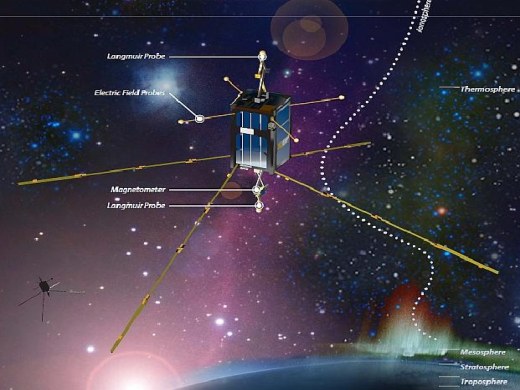
EFP (Electric Field Probe)
One of the most fundamental parameters to observe in the space environment is the electric field which drives the motion of the plasma in the Earth’s ionosphere and magnetosphere. The electric field double-probe is a well-known technique for observing electric fields, in which the potential of pairs of sensors, deployed several meters from the space vehicle, are monitored.
The potential difference between sensors divided by the separation distance gives an estimate of the electric field in the direction of the boom.
The objective of the EFP is to measure DC and AC electric fields. The device consists of a 1 cm diameter sphere mounted at the end of each of the four wire booms.
The sensor is a gold-plated 1 cm diameter solid sphere. The spheres are gold-plated to provide an optimal surface for charges to transfer from the ionosphere to the sensor. By using solid aluminium spheres, a greater moment of inertia about the spinning axis is induced because of the greater mass at a higher moment arm.
Each sensor is mounted in a corner mount, shown in Figure 18. The corner mount has a semi-sphere that cups the electric field probe sensor. The spherical surface on the corner mount that will contact the probe sphere is also gold-plated. This ensures that the surface of the probe will retain the integrity of the surface finish, restricts translation of the sphere in lateral directions, and grounds the sensor to the boom release system.
The EFP makes both DC and AC electric field measurements. The DC measurements are made at equal time steps and telemetered at an 8 Hz rate, thus providing 45º rotational resolution per spacecraft spin and maximizing science return. Oversampling and decimation of the DC signal occur on board to improve both signal-to-noise ratio and to create a characterized filter for the sampled data.
The DC measurements are a subset of the AC measurements and co-incident with the AC measurements. The AC measurements are sampled at 4096 Hz in equal time steps. The AC measurements are processed onboard through an FFT algorithm. The resultant magnitude of three distinct frequencies can then be telemetered at 1 Hz for ground analysis.
The three frequencies selected are 50, 1300, and 2048 Hz.
The first frequency corresponds to the Fresnel scale for GPS (200-300 m), while the latter sample rate enables the resolution of electric field structures that are < 3.5 m. The middle value provides some idea of the spectral shape.
While not the primary science mission, the AC field measurements will contribute to the overall scientific success of the mission in two ways. First, it is known that small-scale density irregularities form at the edges of the SED plumes. What is not known is the exact physical mechanism that produces the irregularities. It could be a gradient-drift instability, which would only involve large-scale DC fields.
However, it could also be related to Farley-Buneman instabilities or Kelvin-Helmholtz instabilities.
Making coincident measurements of the small-scale fluctuating electric field, electron density fluctuations and the larger-scale fields in the presence of SED instabilities will provide new insight into the instability mechanisms.
The second way the AC field measurements will contribute to the science is by adding to the overall understanding of the micro-scale and mesoscale physics occurring on the edges of the SED gradients. It is possible that detailed coupling between the various spatial scales plays an important role in the evolution and growth of large-scale SED plumes. By making small-scale measurements of electric fields, we can help to elucidate the coupling between the physical processes.
DCP (DC Langmuir Probe)
The DICE mission uses two separate spherical DCP sensors operating in the ion saturation region that have a measurement ion density range of 2 x 10⁹ to 2 x 10¹³ m-3 and a minimum resolution of 3 x 10⁸ m-3. The two sensors are deployed on separate fibreglass 8 cm long cylindrical booms, that will extend into the plasma environment, from the top and bottom of the spacecraft along its spin axis (Ref. 3).
The booms are 3 mm in diameter and support 1 cm in diameter spheres. These spheres are gold-plated and conductive, but the booms themselves are electrically insulated from the plasma environment by static dissipative germanium-coated Kapton tape.
Along each spacecraft’s orbital path, spin-stabilized attitude coupled with the DCP deployment geometry results in at least one of the two DCP spheres always facing the velocity vector ram direction (Figure 12).
The use of a spherical probe gives the most uniform ram-projected cross-section area for most of the orbital path, with the exception of high polar latitudes. The DCP sensors are biased to -4 VDC to repel electrons and allow for ion ram current measurements during flight.
Due to the nature of the orbit and the variation of the ionosphere, the Debye length is expected to vary anywhere between a few mm to upwards of 15 cm. However, due to high spacecraft velocity that far exceeds the local ion mobility, the ion ram current collected by the DCP sensors will not be affected by Debye lengths that are larger than the DICE spacecraft and DCP sensor dimensions.
In the nominal operating mode, the measurements from both DCP sensors will be made simultaneously and telemetered at 2 Hz each. Oversampling and decimation of the resultant signal occur between the distinct telemetry sample points to improve signal-to-noise.
TAM (Three-Axis Magnetometer)
In addition to the EFP and DCP devices, a science-grade magnetometer, TAM, will measure field-aligned currents. These measurements will permit accurate identification of storm-time features such as the SED bulge and plume, together with simultaneous co-located electric field measurements which have previously been missing.
Ground Segment
The ground stations of the DICE mission are located at:
• NASA, Wallops Island, VA
• SRI International, Menlo Park, CA.
The public interface for the DICE data will be at ASTRA LLC, and students are expected to play a large role in the DICE data centre. The operational mission will provide material for classes that will serve to motivate students with regard to science, technology, engineering, and mathematics. Students have been the main contributors and participants during regular DICE program status meetings, telecoms, technical interchange meetings, and major reviews.
Existing ground infrastructure:
The DICE mission has demonstrated communications through both the NASA Wallops Island facility in Virginia, and Stanford Research Institute (SRI) satellite communications facility in California. The DICE mission team installed their mission-specific communication equipment at both facilities using standardized hardware and software interfaces. Highly reliable TT&C was achieved at both locations and mission data was downlinked to both locations. Additionally, the team managed the DICE mission remotely from the SDL facility in Logan, UT, through remote terminal sessions.
While the DICE mission only demonstrated operations at two ground stations at different times, the network protocols have been established for linking multiple ground stations to form a more comprehensive ground infrastructure (Ref. 18).
During the operational phase of the DICE mission, two ground stations were used. A facility at NASA Wallops field was used as the primary ground station. This included an 18.29 m dish. The other facility was located at the Stanford Research International 18.3 m dish in Menlo Park, Calif. The ground station used an Ettus Research USRP™ (Universal Software Radio Peripheral) to implement the uplink and downlink transceiver. The USRP hardware was connected to a PC that also provided a means to record all downlink data for post-processing. 21)
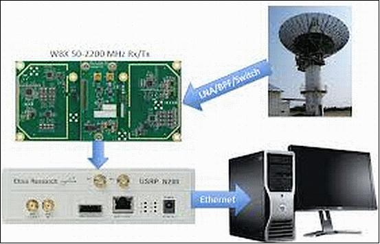
USRP and Satellite-Ground Communication:
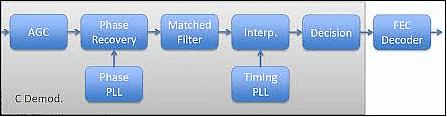
The USRP N210 was chosen to meet the demanding requirements for the mission's ground station. Interfaced with a PC, the USRP device allowed the team to access the RF signals, demodulate, and decode the signals. During a downlink session, the USRP, PC, and a storage device were used to record RF samples, which would be post-processed using GNU Radio and C++. A block diagram of the receiver system can be seen in Figure 21.
References
1) URL: http://www.sdl.usu.edu/programs/dice
2) Geoff Crowley, Chad Fish, Charles Swenson, Gary Bust, Aroh Barjatya, Miguel Larsen, and the USU Student Team, “Dynamic Ionosphere CubeSat Experiment,” 2010 CubeSat Developers' Workshop, CalPoly, San Luis Obispo, CA, USA, April 21-23, 2010, URL: http://mstl.atl.calpoly.edu/~workshop/archive/2010/Spring/Day%201/1110%20-%20Crowley%20-%20DICE.pdf
3) Geoff Crowley, Chad Fish, Charles Swenson, Robert Burt, Tim Neilsen, Aroh Barjatya, Gary Bust, Miguel Larsen, “Dynamic Ionosphere Cubesat Experiment (DICE),” Proceedings of the 24th Annual AIAA/USU Conference on Small Satellites, Logan, UT, USA, Aug. 9-12, 2010, SSC10-III-7
4) Therese Moretto Jorgensen, “The Scientific Promise of Small Satellite Missions: Mindset change and research utilization of CubeSats,” 2009, URL: http://www.gwu.edu/~spi/assets/docs/111209Jorgensen.PDF
5) Erik Stromberg, “DICE CubeSat Mission,” 8th Annual CubeSat Developers’ Workshop, CalPoly, San Luis Obispo, CA, USA, April 20-22, 2011, URL: http://www.cubesat.org/.../wed_p5.00_stromberg_dice_cswkshp_2011_stromberg.pdf
6) Geoff Crowley, Chad Fish, Charles Swenson, Robert Burt, Eric Stromberg, Tim Neilsen, Steve Burr, Aroh Barjatya, Gary Bust, Miguel Larsen, “Dynamic Ionosphere Cubesat Experiment (DICE),” Proceedings of the 25th Annual AIAA/USU Conference on Small Satellites, Logan, UT, USA, Aug. 8-11, 2011, paper: SSC11-XII-6
7) Chad Fish, Charles Swenson, Tim Neilsen, Bryan Bingham, Jake Gunther, Erik Stromberg, Steven Burr, Robert Burt, Mitch Whitely, Geoff Crowley, Irfan Azeem, Marcin Pilinski, Aroh Barjatya, Justin Petersen, “DICE Mission Design, Development, and Implementation: Success and Challenges,” Proceedings of the 26th Annual AIAA/USU Conference on Small Satellites, Logan, Utah, USA, August 13-16, 2012, paper: SSC12-XI-1, URL: http://digitalcommons.usu.edu/cgi/viewcontent.cgi?article=1087&context=smallsat
8) Steven Reed Burr, “The Design and Implementation of the Dynamic Ionosphere Cubesat Experiment (Dice) Science Instruments,” All Graduate Theses and Dissertations, July 1, 2013, URL: http://digitalcommons.usu.edu/cgi/viewcontent.cgi?article=2747&context=etd
9) https://web.archive.org/web/20130731110343/http://astraspace.net/research-development/dicecubesat-mission/
10) C. S. Fish, C. M. Swenson, G. Crowley, A. Barjatya, T. Neilsen, J. Gunther, I. Azeem, M. Pilinski, R. Wilder, D. Allen, M. Anderson, B. Bingham, K. Bradford, S. Burr, R. Burt, B. Byers, J. Cook, K. Davis, C. Frazier, S. Grover,G. Hansen, S. Jensen, R. LeBaron, J. Martineau, J. Miller, J. Nelsen, W. Nelson, P. Patterson, E. Stromberg, J. Tran, S. Wassom, C. Weston, M. Whiteley, Q. Young, J. Petersen, S. Schaire, C. R. Davis, M. Bokaie, R. Fullmer, R. Baktur, J. Sojka, M. Cousins, “Design, Development, Implementation, and On-orbit Performance of the Dynamic Ionosphere CubeSat Experiment Mission,” Springer, Space Science Review, Published online: Feb. 06, 2014, DOI 10.1007/s11214-014-0034-x. URL: https://link.springer.com/article/10.1007/s11214-014-0034-x
11) https://web.archive.org/web/20180403185013/http://www.sdl.usu.edu:80/downloads/dice.pdf
12) https://web.archive.org/web/20151030090936/http://www.sdl.usu.edu/downloads/pearl.pdf
13) “NASA Launches Multi-Talented Earth-Observing Satellite,” Space Travel, October 28, 2011, URL: http://www.space-travel.com/reports/NASA_Launches_Multi_Talented_Earth_Observing_Satellite_999.html
14) “CubeSat ELaNa III Launch on NPP Mission,” NASA, October 2011, URL: http://www.nasa.gov/pdf/598567main_65121-2011-CA000-NPP_CubeSat_Factsheet_FINAL.pdf
15) Information provided by Erik Stromberg of USU/SDL, Logan, UT, USA
16) Steven Grover, Keith Bradford, Mark Anderson, Erik Stromberg, Brian Sharp, Steve Burr, “Miniature Wire Boom System for Nano Satellites,” Proceedings of the 24th Annual AIAA/USU Conference on Small Satellites, Logan, UT, USA, Aug. 9-12, 2010, SSC10-XII-5
17) “National Scientific Foundation (NSF) CubeSat-based science missions for Geospace and Atmospheric Research,” Annual Report, October 2013, URL: http://www.nsf.gov/geo/ags/uars/cubesat/nsf-nasa-annual-report-cubesat-2013.pdf
18) Edward W. Kneller, Kevin L. Hyer, Todd McIntyre, David K. Jones, Charles Swenson, “Cadet: A High Data Rate Software Defined Radio for SmallSat Applications,” Proceedings of the 26th Annual AIAA/USU Conference on Small Satellites, Logan, Utah, USA, August 13-16, 2012, paper: SSC12-X-4, URL: http://digitalcommons.usu.edu/cgi/viewcontent.cgi?article=1083&context=smallsat
19) Information provided by Erik Stromberg of USU/SDL (Utah State University/Space Dynamics Laboratory).
20) Charles Swenson, Chad Fish, Erik Stromberg, ECE2250 Class, Bryan Bingham, Joshua Martineau, Phillip Anderson, “The International Space Station as a Launch Platform for CubeSats to Study Space Weather,” and “ DICE First contacts on November 1, 2011,” p. 16, 3rd Nano-Satellite Symposium, Kitakyushu, Japan, December 12-13, 2011
21) Jacob Gunther, “Dynamic Ionosphere CubeSat Experiment – High-Speed Satellite Ground Station,” 2014, URL: http://www.ettus.com/application/detail/dynamic-ionosphere-cubesat-experiment-high-speed-satellite-ground-station
The information compiled and edited in this article was provided by Herbert J. Kramer from his documentation of: ”Observation of the Earth and Its Environment: Survey of Missions and Sensors” (Springer Verlag) as well as many other sources after the publication of the 4th edition in 2002. - Comments and corrections to this article are always welcome for further updates.(eoportal@symbios.space)