PRISMA (Hyperspectral)
EO
Atmosphere
Aerosols
High resolution optical imagers
Launched on 22 March, 2019, PRISMA is a medium-resolution hyperspectral imaging satellite, developed, owned and operated by ASI (Agenzia Spaziale Italiana). It is the successor to the discontinued HypSEO (Hyperspectral Satellite for Earth Observation) mission and has a planned mission duration of 5 years.
Quick facts
Overview
| Mission type | EO |
| Agency | ASI |
| Mission status | Operational (nominal) |
| Launch date | 22 Mar 2019 |
| Measurement domain | Atmosphere, Land |
| Measurement category | Aerosols, Multi-purpose imagery (land), Vegetation, Albedo and reflectance, Trace gases (excluding ozone) |
| Measurement detailed | Land surface imagery, Vegetation type, Earth surface albedo, Land cover, CH4 Mole Fraction, Volcanic ash, CO2 Mole Fraction |
| Instruments | HYC, PAN CAMERA |
| Instrument type | High resolution optical imagers, Hyperspectral imagers |
| CEOS EO Handbook | See PRISMA (Hyperspectral) summary |

Summary
Mission Capabilities
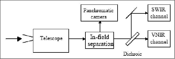
PRISMA carries two sensor instruments, the HYC (Hyperspectral Camera) module and the PAN (Panchromatic Camera) module. The HYC sensor is a prism spectrometer for two bands, VIS/NIR (Visible/Near Infrared) and NIR/SWIR (Near Infrared/Shortwave Infrared), with a total of 239 channels across both bands. Its primary mission objective is the high resolution hyperspectral imaging of land, vegetation, inner waters and coastal zones. The second sensor module, PAN, is a high-resolution optical imager with one channel and is co-registered with HYC data to allow testing of image fusion techniques.
Performance Specifications
The HYC module has a spatial resolution of 30 m and operates in two bands, a 66 channel VIS/NIR band with a spectral interval of 400-1010 nm, and a 173 channel NIR/SWIR band with a spectral interval of 920-2505 nm. It uses a pushbroom scanning technique with a swath width of 30 km, and a field of regard of 1000 km either side. The PAN module also uses a pushbroom scanning technique, with identical swath width and field of regard but spatial resolution of 5 m.
PRISMA is in a sun-synchronous orbit, with an altitude of 614 km, an inclination of 98.19° and its LTDN (Local Time on Descending Node) is at 1030 hours.
Space and Hardware Components
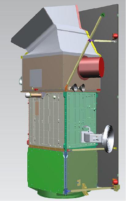
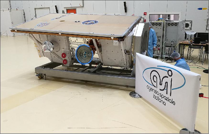
The PRISMA spacecraft bus is based on an MITA (Minisatellite for Advanced Technology) design and was developed by CGS (Carlo Gavazzi Space S.p.A) with dimensions 1.751 x 1.545 x 3.4 m. In terms of RF (Radio-Frequency) communications, TT&C (Tracking, Telemetry and Command) uses S-band transmission, while the X-band is used for payload data downlink, with the PDHT (Payload Data Handling and Transmission) subsystem dedicated to processing payload data for transmission.
PRISMA (Hyperspectral Precursor and Application Mission)
Spacecraft Launch Mission Status Sensor Complement Ground Segment References
PRISMA (PRecursore IperSpettrale della Missione Applicativa) is a medium-resolution hyperspectral imaging mission of the Italian Space Agency ASI (Agenzia Spaziale Italiana) under development as of 2008. It is a follow-on project of the previously started HypSEO (Hyperspectral Satellite for Earth Observation) program whose phase B was completed in 2002 and then discontinued. - The PRISMA project is conceived as a pre-operational and technology demonstrator mission, focused on the development and delivery of hyperspectral products and the qualification of the hyperspectral payload in space. 1) 2) 3) 4) 5) 6) 7) 8)
PRISMA will focus on the needs of the Italian institutional and research entities. The mission objectives are:
• to develop a small satellite mission entirely in Italy for monitoring of natural resources and atmospheric characteristics (information on land cover and crop status, pollution quality of inland waters, status of coastal zones and the Mediterranean Sea, soil mixture and carbon cycle), taking advantage of the previous developments carried out by ASI
• to provide the standard data products with short delay periods after reception to the scientific community to address the various selected applications, such as those related to quality and protection of the environment, sustainable development, climate change, etc.
• to demonstrate new technologies in orbit.
The overall objective is to provide a global observation capability - the specific areas of interest to be covered are Europe and the Mediterranean region. The PRISMA mission development is completely funded by ASI (Italian Space Agency) and includes the system development program and the related applications and research activities.
The industrial core team is formed by Carlo Gavazzi Space (CGS), Selex Galileo (SG) and Rheinmetall Italia (RhI), and also includes all the key national industries which have already acquired specific knowhow and expertise. ASI awarded the prime contract to CGS in Dec. 2007.
Note: Selex ES is an international electronics and information technology business, which is part of Finmeccanica S.p.A. It is based in Italy and the UK, and was formed in January 2013, following Finmeccanica's decision to combine its existing SELEX Galileo, SELEX Elsag and SELEX Sistemi Integrati businesses.
The following tasks are assigned to the core team:
• CGS: Responsible for project management, contract management and system engineering, both for space segment and ground segment, design, development and integration of the platform, for system AIV (Assembly, Integration and Verification) activities, satellite EGSE, support to launcher interface. In the frame of the Ground Segment, CGS is responsible of the overall data processing in the IDHS (Instrument Data Handling System) of the Level 2 standard products development.
• Selex ES (former Selex Galileo became Selex ES in January 2013): Responsible for design, development, integration, test and calibration of the complete hyperspectral instrument, PAN camera and of its test equipment [MGSE (Mechanical Ground Support Equipment), EGSE (Electrical Ground Support Equipment) and OGSE (Optical Ground Support Equipment)]. For what concern the platform, Selex ES will also supply solar panels, AA-STR (APS Autonomous Star Tracker) devices for attitude determination and the on-board PCDU (Power Conditioning and Distribution Unit). In the frame of the Ground Segment, GA will be responsible for the overall Data Processing in the IDHS with direct responsibility of level 0 and level 1 standard products development.
• RhI: responsible for thermo-mechanical engineering of the satellite, development and integration of the structure and thermal subsystem of the platform, for platform and payload structural model, for launcher interface, for satellite thermo-mechanical AIV and relevant environmental qualification, for satellite MGSE and for launch campaign. RHI will also supply the solar panel mechanical substrate.
Mission Phases
For the PRISMA mission operations the standard operational phases have been identified. The Pre-Launch phase will cover the activities to be performed with the satellite ready to be launched. Furthermore, during this phase, planning, procedures development and validation, training activity, exercises and rehearsal will be performed. The satellite functionalities and integrity will be verified by dedicated tests. The final authorization to launch will be given by a dedicated review (Launch Readiness Review) board, after the verification that the complete system (satellite, launcher, SCC, nominal and LEOP ground stations) is operating.
The LEOP (Launch and Early Operational Phase) of the PRISMA mission is the phase during which the spacecraft is launched into its initial orbit, its systems activated and checked-out, and sequence of events carried out.
The commissioning phase for the PRISMA mission includes:
- In-orbit test (IOT) phase for the actual commissioning activities relevant to Space Segment, Ground Segment, ILS&OPS and System, as well as the payload in orbit calibration activities
- Operative Qualification (OQ) phase aiming to validate the PRISMA system in terms of system performance stability and products certification, based on key performance parameters measure and verification.
After the Operative Qualification period the handover process will be completed and system accepted. During the routine phase PRISMA will provide the hyperspectral/panchromatic image acquisition and processing. Periodically, during the routine phase, the payload calibration (without interruption of the nominal observation campaign) and orbital maneuvers (with temporarily interruption of imaging activities) are performed.
At the end of the operational lifetime of the mission, currently scheduled for five years, the disposal phase has the purpose to conclude the PRISMA mission placing the satellite in a safe configuration.
Spacecraft
The system is based on a minisatellite bus of MITA heritage and is being developed at Carlo Gavazzi Space SpA of Milan, Italy (CGS). The PRISMA platform represents a significant evolution of the MITA/AGILE platform developed as standard Italian small satellites platform (launch of AGILE on April 23, 2007). The main PRISMA improvements are:
• Enhanced attitude control system with pointing agility. A spacecraft body pointing capability of ±14.7º (off-nadir) is provided in cross-track
• Propulsion subsystem for orbit control and final disposal
The main performance features are:
• Attitude determination: 0.015º with 3-axis stabilization
• Pointing accuracy: 0.07º in all 3 axes
• Orbit determination: 20 m (onboard) -> image geolocation: 168 m.
OBDH (On Board Data Handling) subsystem: OBDH is in charge of on board telemetry and telecommand management, ground generated commands execution, AOCS, power management, monitoring of main platform H/K parameters, payload monitoring and image downloading during ground contacts.
EPS (Electrical Power Subsystem): Power is provided by fixed solar panels and by two Lithium-Ion battery packs during eclipse periods and during the attitude acquisition phase. The electronics to convert and distribute the power to the satellite users is included in the PCDU (Power Control and Distribution Unit and managed by the OBDH.
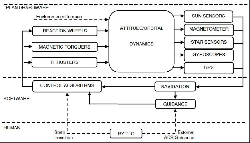
AOCS (Attitude and Orbit Control Subsystem): The AOCS equipment consists of the following sensing devices (Figure 2): 9)
• 2 star sensors and 6 gyroscopes for accurate attitude determination
• 2 magnetometers and 24 sun presence sensors for coarse attitude determination
• 2 GPS receivers for position and velocity determination.
The actuators are:
• 4 reaction wheels placed in a pyramidal configuration and used for fine attitude pointings
• 3 magnetic torquers for coarse attitude pointings and reaction wheel desaturation
• 2 thrusters for orbital maneuvers.
The sensor measurements are given as input to the navigation block which is in charge of estimating the current system state. Merging this information with guidance profiles, control algorithms derive actuators commands.
Guidance: Different guidance schemes have been implemented to support the different mission phases. Guidance profiles can be divided in the following categories:
- 1-axis sun-pointing guidance, used in Safe mode
- 3-axes spin-phased sun-pointing guidance, used in standby mode
- Ground-loaded 3-axes guidance, used in ground guided and orbit control modes
- Autonomous or ground loaded guidance.
In the 1-axis/3-axes sun-pointing guidance, the axis normal to solar panels is kept aligned with the sun direction. The 3-axes spin-phased sun-pointing guidance is specifically designed for thermal control in order to keep the payload radiator far away from Earth while spinning the satellite around the solar panel axes.
Image acquisition, data download, orbit correction maneuver, flat-field pointing calibrations and moon pointing calibration require leaving the sun pointing attitude and follow guidance profiles uploaded from the ground. PRISMA-I is specifically designed also for this type of maneuver. Typical guidance profiles need to fulfil specific requirements regarding angular acceleration and velocity constraints, sensors occultation, payload radiator/optics constraints, battery consumption, Earth rotation compensation and X-band antenna pointings.
Navigation: Navigation is organized in a series of sub-functions, which, based on a subset of the available sensors, output the estimated satellite state. Several estimators are implemented in the navigation filter. Data from PRISMA-I sensors are collected and elaborated by different on board estimators in order to have coarse and fine estimates of the satellite state in terms of rates, accelerations, position, attitude, etc. The strategy for estimator selection is based on sensors availability and the mission phase. Different estimation performance are required depending on the AOCS control mode actually in use. The principal navigation features needed in the PRISMA-I AOCS are:
- Attitude/rate coarse estimation functions
- Attitude/rate fine estimation functions
- Kalman filter for accurate state estimation from star sensor and gyroscopes measures
- Sun propagator, orbit propagator and Earth magnetic field model to support navigation filter.
The coarse rate estimation functions are based on Sun presence sensors and magnetometers measures, the simplest and most reliable set of available sensors. The coarse attitude estimation is performed merging these data with the information given by the on board sun propagator and Earth magnetic field propagator. - Fine rate and attitude estimates are obtained merging star sensors and gyroscopes measures in order to continuously provide accurate attitude information also in case of star sensors blinding or invalid measures.
AOCS control: The control function is devoted to the calculation of the control actions commanded to actuators. The controller is able to support the following functionalities:
- Sun pointing for power generation and safe state
- Fine nadir pointing for image acquisition
- Fine moon pointing for payload calibration
- Fast maneuvers from the sun to other pointings fulfilling various geometric constraints
- Orbital maneuvers.
AOCS performance in terms of pointing accuracy and maneuver execution time: The AOCS guarantees an AKE (Absolute Knowledge Error) of < 12 arcsec (single axis, 3σ) and an APE (Absolute Performance Error) of < 60 arcsec (single axis, 3σ).
The agile spacecraft features a body-pointing capability of ±30º in cross-track. Roll maneuvers will be performed to provide the satellite relook capability, and ±5° pitch maneuvers may be performed for glint avoidance.
Thermal control: The satellite thermal control is mainly passive and it is realized by placing the most dissipating devices on radiating surfaces. Dedicated thermal control will be implemented for the Li-Ion battery, for the payload detectors and for the propulsion subsystem.
Structure: The spacecraft structure consists of a frame made of tubes and reinforcing side panels made up by an Al-Al honeycomb structure which supports internal subsystem hardware. The spacecraft dimensions are: 1751 x 1545 x 3400 (L x W x H) mm. The spacecraft launch mass is < 550 kg, power consumption = 350 W (average) and 720 W (max). The mission design life is 5 years.
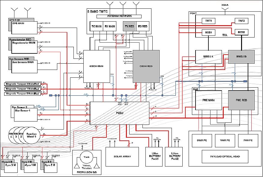
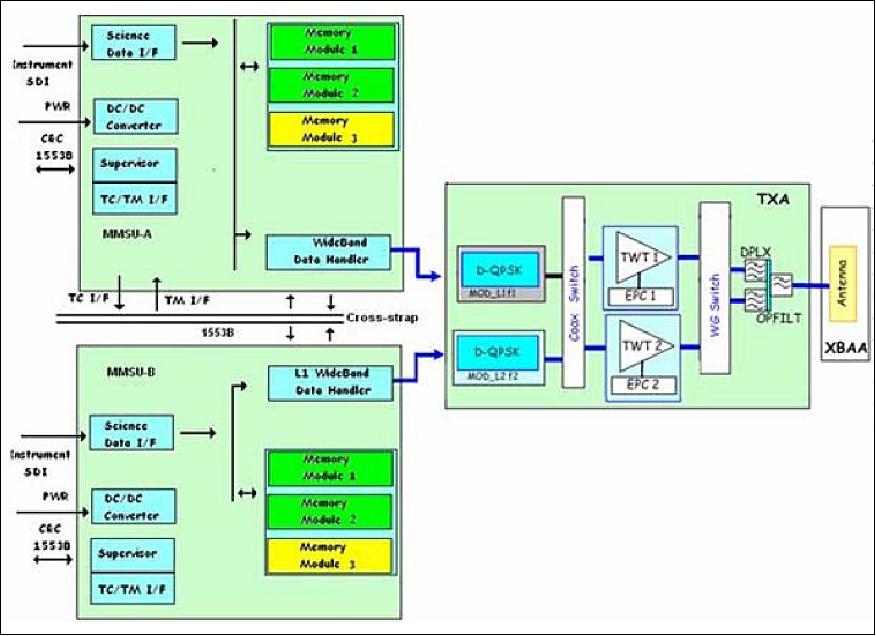
RF communications: The S-band is used for TT&C communications. The X-band is used for the downlink of the payload data. The PDHT (Payload Data Handling & Transmission) subsystem, of COSMO-SkyMed heritage, is dedicated to the processing of the payload data for the X-band downlink.
Input data rate from imager instrument | up to 600 Mbit/s |
Available memory @ EOL (End of Life) | 256 Gbit storage capacity after 3 years |
Data encryption | Yes |
Downlink data rate | 155 Mbit/s |
PDHT mass | 42 kg |
PDHT reliability | > 0.96 |
Development Status
• June 20, 2017: OHB Italia SpA and Arianespace announced the signature of the launch contract for the Italian Space Agency's PRISMA (PRecursore IperSpettrale della Missione Applicativa) satellite. 16) 17)
Launch
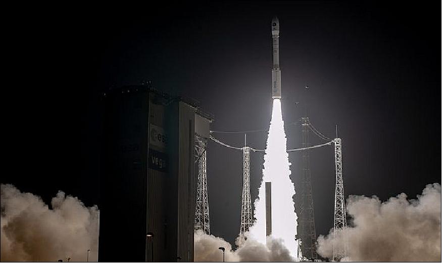
The PRISMA spacecraft was launched on 22 March 2019 (01:50:35 UTC, or 21 March 22:50:35 local time in French Guiana) on a Vega launch vehicle from Kourou, designated VV14. With a mass at liftoff of 879 kg, PPRISM was maneuvered into its target Sun-synchronous orbit about 54 minutes into the mission after two burns of Vega's upper stage. 13) 14) 15)
Following the launch, Arianespace Chief Executive Officer Stéphane Israël said: "With today's successful launch of the PRISMA Earth observation satellite, Arianespace has orbited its 600th satellite! We are very proud to continue performing our primary vocation of ensuring independent access to space for Europe, with a focus this evening on Italy. Today's mission, carried out for the Italian space agency, ASI, and the Italian industry consortium led by OHB Italia SpA and Leonardo SpA, illustrates the reliability of the Vega launcher, which has performed its 14th successful launch in a row.
Orbit: Sun-synchronous circular, altitude = 615 km, inclination = 97.85º, period ~ 98 minutes, orbit repeat cycle = 29 days and relook capability of 7 days with roll maneuver, LTDN (Local Time of equator crossing on Descending Node) = 10:30 hours.
The satellite will primarily operate in a "user driven" targeting mode with a re-targeting period of < 7 days and a response time of < 14 days. To fill the system capacity, a "data driven" background mission mode will be considered as well.
The foreseen operational life of the mission is five years.
Mission Status
• October 2019: The PRISMA payload is functioning nominally following its launch and is presently in the last phase of its commissioning stage. The initial outcomes have aligned well with expectations. The images obtained are appropriate for scientific and applied purposes. 18)

Sensor Complement
PRISMA
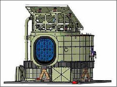
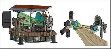
PRISMA (the name of the mission and of the sensor are identical) is an advanced hyperspectral instrument including a panchromatic camera at medium resolution. Selex ES (a Finmeccanica company) of Campi Bisenzio, Italy, is the prime contractor for the design and development of the PRISMA instrument. The design is based on a pushbroom type observation concept providing hyperspectral imagery (~ 250 bands) at a spatial resolution of 30 m on a swath of 30 km. The spectral resolution is better than 12 nm in a spectral range of 400-2500 nm (VNIR and SWIR regions). In parallel, Pan (Panchromatic) imagery is provided at a spatial resolution of 5 m; the Pan data is co-registered with the Hyp (Hyperspectral) data to permit testing of image fusion techniques. 19) 20) 21) 22) 23) 24) 25) 26) 27) 28) 29)
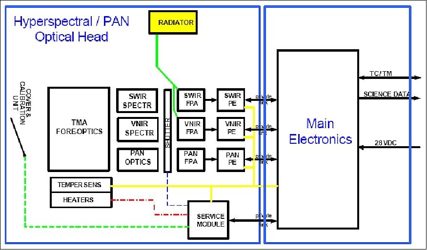
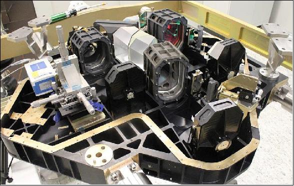
The PRISMA instrument is based on a prism spectrometer concept and comprised of the units: the Hyp/Pan optical head and the main electronics box. The physical separation of the units provides a better mass distribution on the spacecraft bus. The common telescope of the Hyp/Pan and optical head units is collecting the incoming radiation of both channels, which is dispersed by two spectrometers; the photons are converted to electrons by suitable detectors, then the electrical signals are amplified and converted into a digital data stream.
The electronics box has the function to control the instrument and to handle the imagery bit stream according to agreed-on protocols. The cooling of the SWIR detector array is provided by means of a cold space facing passive radiator.
Parameter | VNIR channel | SWIR channel | Pan channel |
Spectral range | 400-1010 nm | 920-2505 nm | 400-700 nm |
Spectral resolution (FWHM) | ≤ 12 nm | ≤ 12 nm | - |
Spectral bands | 66 | 173 | 1 |
SNR (Signal-to-Noise Ratio) | 200 in the range 0.4-1.0 µm | 200 in the range 1.0-1.75 µm |
240 |
MTF (Modulation Transfer Function) | > 0.8 @ Nyquist frequency | > 0.7 @ Nyquist frequency | > 0.2 @ Nyquist frequency |
Swath width | 30 km (FOV = 2.45º) | ||
Spatial resolution | 30 m | 5 m | |
Spatial detector pixels |
| 1000 x 256 with 30 µm pitch | 6000 |
IFOV | 48.34 µrad | ||
Telescope type | TMA (Three Mirror Anastigmat) | ||
Telescope aperture | 210 mm entrance pupil diameter | ||
Telescope effective focal length, F-number | 620 mm, 2.95 | ||
Data quantization | 12 bit | ||
Frame rate | 230 Hz | ||
Main electronics box size, mass | ~400 mm x 300 mm x 250 mm, < 8 kg | ||
Instrument size | 770 mm (L) x 590 mm (W) x 780 mm (H) | ||
Instrument mass | < 90 kg | ||
Instrument power | < 110 W (average), < 50 W (standby) | ||
Cooling system | Passive radiator |
| |
FOR (Field of Regard) | ±15º (body pointing capability of the S/C to direct observations in cross-track) | ||
In-flight temperature control (Ref. 18)
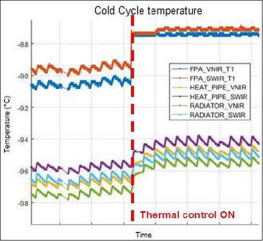
The critical in-flight temperature control of the PRISMA instrument relies on three separate passive control loops, one dedicated to the temperature of the optical bench, the PAN detector and several optics and two to the temperature of the VNIR and SWIR FPAs (Focal Plane Assemblies).
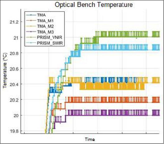
The temperature of the optical bench needs to be controlled at a stable value in the range 21°C ±3°C with a spatial gradient lower than 1°C. The nominal temperature of the VNIR and SWIR FPAs needs to be controlled at stable value in the range -83 to-100°C, in order to guarantee the required performance of the detector in terms of dark signal. The graphs in Figure 9 and Figure 10 demonstrate the performances of the three temperature control loops.
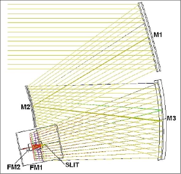
Optical design: The design of the optical head system consists of a common telescope and two spectrometers, operating in the VNIR and SWIR bands, and a panchromatic camera. The telescope configuration consists of a TMA (Three Mirror Anastigmat) implementation to assure excellent optical quality with a minimum number of optical elements. The telescope features three aspherical mirrors with an entrance aperture of 210 mm and an effective focal length of 620 mm. The entrance pupil diameter choice allows the system to meet the high required SNR (Signal-to-Noise Ratio) with an f/number selection to achieve a high geometrical performance in terms of smile effect, keystone effect, and co-registration. The telescope has a diffraction-limited MTF (Modulation Transfer Function) and an energy within a 30 x 30 µm reference pixel of 80%.
The imaging spectrometers are based on a prism solution so to obtain high efficiency and low polarization sensitivity. The good efficiency allows to reduce the instrument dimension and mass with less demanding resources to the S/C and less criticalities for the optics design.
The selected VNIR and SWIR FPA (Focal Plane Array) detectors exhibit high performance and can be interfaced with an identical proximity electronics. They require to be cooled at a moderate low temperature (185 K) by means of a passive radiator facing the cold space. The configuration is designed to match a detector array with a pixel size of 30 µm for both VNIR and SWIR channels, and 6.5 µm for the PAN. The detection chain involves three focal planes which are physically accommodated on the optical bench.
Due to the demanding requirements on the radiometric accuracy an in-flight ICU (Internal Calibration Unit) has been designed so to allow operations of absolute and relative radiometric calibration and spectral calibration.
The stray light and ghost image effects in the telescope are being controlled by:
• internal baffling which prevents light from reaching the slit outside the nominal path
• conventional blacking of most internal structure surfaces.
An external baffle is implemented to contribute to the reduction of thermal radiant inputs to the telescope optics. A slit common to the VNIR and SWIR spectrometers (identical FOVs) is placed in the focal plane of the telescope. The separation between the VNIR and SWIR optical path is realized with a DBS (Dichroic Beam Splitter) to improve the co-registration requirement.
The mechanical design of the instrument makes use of the following guidelines/design drivers:
• the three optical channels (VNIR, SWIR, Pan) must be spaced out as far as possible and located on the instrument's side facing cold space
• the proximity electronics must be kept close to the FPAs (Focal Plane Assembly) to minimize the lengths of the flex cables
• the most relevant masses must be located as close as possible to the mechanical interface between the instrument and the bus
• the instrument entrance port has to be closed to avoid contamination of the internal optics.
The optical bench supporting the optics and the FPAs is realized in aluminum alloy to reduce the instrument mass.
The SWIR detector cooling is realized using a cold space facing radiator. The thermal design of the instrument is based on an architecture with the following characteristics:
- The SWIR detector is cooled to a temperature range of 160-180 K
- The VNIR detector temperature is kept in the range of 240-250 K
- The heat fluxes from the electronic warm parts to the cold zones of the instrument are reduced to a minimum
- The optics components, contained in an insulated optical bench, are confined to a relatively tight temperature range of 2-4º C by dedicated thermal controls to provide a good thermo-mechanical stability
- Specific part of the spectrometer, like the FPA and its cold shield, are positioned close to the radiator to permit a good passive system efficiency
- The optical subsystems have to be maintained thermally insulated from the supporting structure, in particular from the parts of the colder temperature range.
Spectrometer: The spectrometer design implements a prism solution and a patented concept of Selex ES. The use of refractive prisms, optimized for each band, allows a much higher efficiency and lower polarization sensitivity than grating implementations. In this way it is possible to achieve the required SNR with a relatively small telescope entrance pupil diameter, offering an advantage in size and mass of the instrument.
The overall instrument spectral radiation (400-2505 nm) is split into two channels (VNIR and SWIR), adopting two different focal plane arrays. The VNIR covers the range (400 -1010 nm) with 66 spectral bands, while the SWIR channel range is (920-2505 nm) with 173 bands. Due to the adopted optical design, the spectral dispersion is not constant with wavelength.
The spectral dispersion is achieved by prisms placed in parallel beams, designed to achieve the required high optical quality in terms of PSF (Point Spread Function), smile, and keystone effects. The smile and keystone effects of the spectrometer are well corrected. The errors are contained within 10% of the pixel, for both of the VNIR and SWIR detector plane arrays. The optical design provides a transparency to reach the required SNR for a typical scenario of 30% reflectance at 30º SZA (Sun Zenith Angle) at TOA (Top of Atmosphere) for the mid-latitude summer.
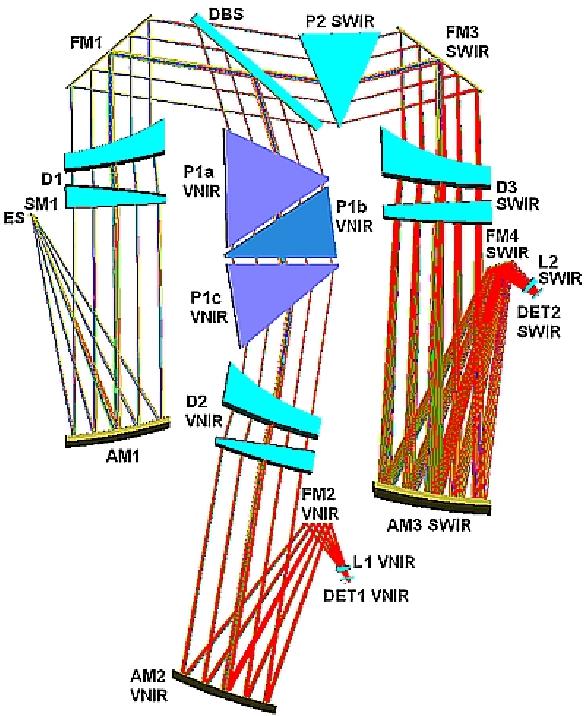
Panchromatic camera: The Pan channel is obtained by separating the main beam coming from the TMA telescope by an in-field separation technique complemented by a second slit parallel to the one of the spectrometers. The Pan image is obtained using a three mirror optical relay that is diffraction-limited for wavelengths > 400 nm.
The field separation effect is a constant offset (in terms of geo-location) between hyperspectral and panchromatic images, which will be taken into account by the image processing algorithms, when co-registering the hyperspectral and panchromatic images. The distance between the two fields will be kept minimal, taking into account:
• mechanical accommodation, which shall limit the minimum feasible physical distance on the focal plane
• temporal co-registration of the Hyp/Pan images, i.e. having two fields means acquiring Hyp and Pan images of the same zone at different times.
The selected layout of the panchromatic unit is a modified Offner configuration (1.3x) with a corrector objective. A folding mirror is placed before the TMA image plane in order to fold the optical path of the rays towards an available, unused space of the optical bench.
The optical layout of the Pan channel comprises three spherical mirrors, two of them decentered, two folding mirrors, and three lenses in fused silica. The mirrors of the TMA telescope and Pan relay are being realized using Schott Zerodur glass, hollowing out the back surfaces to reduce the mass up to 50%. The Pan detector is a linear array with 6000 pixels and a pitch of 6.5 µm.
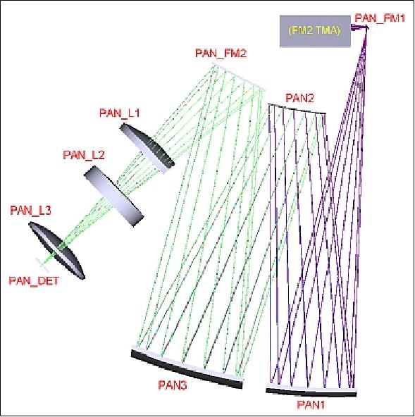
The optical axis of the Pan device is slightly tilted with respect to that of the spectrometer; the off-axis separation between the spectrometer and the Pan device is about 2.84 mm, which produces a field separation on ground of < 3 km. This is the optimum distance compliant with mechanical and manufacturing constraints to reduce the field separation on the ground to a minimum.
The Pan device is optimized over the entire visible spectral range (0.4 – 0.7 µm). The Nyquist frequency is 77 cy/mm (6.5 µm is the pixel size); the optical quality of the Pan device is excellent over the full spectral range.
Instrument Calibration
The in-flight ICU (Internal Calibration Unit) is designed to allow the support of absolute and relative radiometric calibrations and spectral calibrations. The ICU utilizes a very compact optical path, able to image the sunlight through a dedicated solar entrance port via an internal diffuser, seen during the calibration activity by the primary mirror of the TMA telescope. The calibration unit consists of a solar port cover mechanism, filters and spectral lamps. Dark calibration is implemented by means of a lightweight shutter placed in front of the optical slit.
The ICU input spectral radiance for calibration is generated by the Sun (ICU_S mode) or by Internal Sources (ICU_IS mode), through a dedicated optical path. The objective of the ICU is the illumination of the whole instrument pupil and FOV by the reference radiation passing through the same optical path of the Earth-observed signal: in fact a calibration dedicated optical path (both for the sun and for the internal sources) is realized to impinge the back surface of the main port cover. This is provided with a metallic diffuser, that allows a stationary illumination directly on the telescope primary mirror, filling the whole entrance pupil of the telescope.
Dark frames are periodically acquired by closing the shutter located at the spectrometer entrance slit, allowing the offset background subtraction from the ICU internal sources.
| ICU_S | ICU_IS |
Primary objective | Absolute radiometric calibration | - Instrument health check |
Secondary objective | - Relative radiometric calibration | Absolute radiometric calibration |
Operative requirements | This function can be performed in a particular region of the orbit | This function can be carried out independently of the orbital position of the spacecraft |
Repetition frequency | The function shall be carried out every 150 orbits (TBC) representing a measurement in periods of ~ 10 days. This time interval is considered a minimum period for which the variation of the internal sources indicate an appreciable/detectable value. | This function shall be performed immediately before and after each observation session. This is required to subtract the corrected BKG frame from each acquired OBS frame. The BKG shall be obtained by interpolating dedicated acquisitions performed as close as possible to the time of acquisition. |
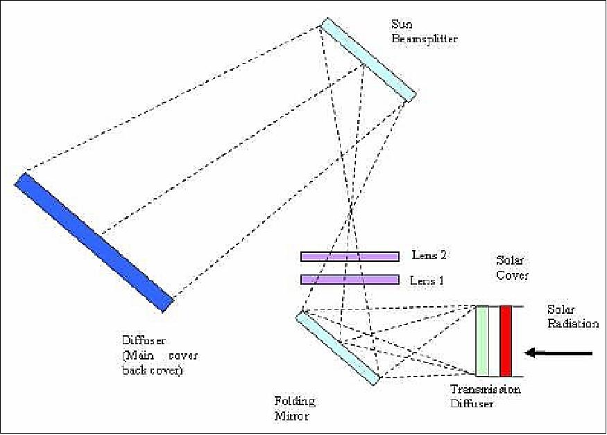
ICU_S mode: During sun calibration, the sun port cover shall be opened for the time strictly needed to perform the acquisition. The solar radiation enters into the instrument through the sun port, passes a transmission diffuser and then, by means of a flat folding mirror, a dedicated relay optics and the Sun Beam Splitter (optimized to maximize the radiance from the lamp sources), it is redirected towards the internal (back) surface of the main port cover (Figure 18).
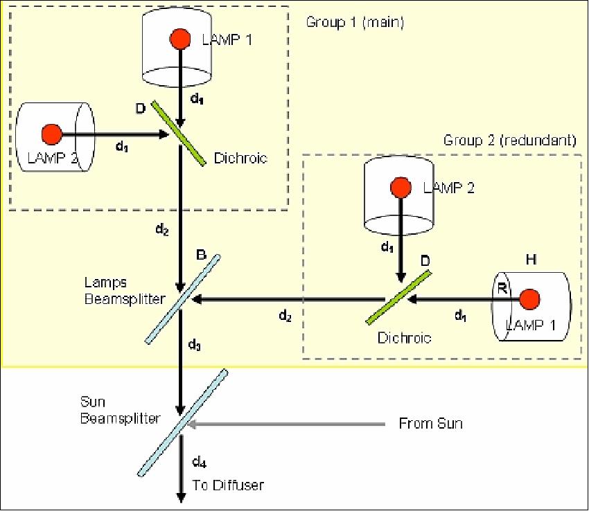
ICU_Is mode: ICU unit is provided by radiance calibrated tungsten lamps positioned in dedicated reflecting lamp-housings. The lamp-house aperture supports a transmittance filter having calibrated spectral signatures. The internal calibration sources are composed by two equal groups (main and redundant) of a couple of lamps: one lamp for VNIR and the other for the SWIR channel. The VNIR and SWIR lamps differ on the filter spectral features and on the lamp-housing coating.
The radiation emitted by the two lamp-housings are combined by means of a dichroic filter (optimized to transmit the VNIR and to reflect the SWIR) radiation. A dedicated beam splitter has the purpose to combine the beams coming from the Main or the redundant group folding it toward the Sun Beam Splitter (this component is exactly the same used for the solar calibration). At the end, the radiation passes through the splitter and illuminates the whole main cover diffuser. The path of the lamp beams is shown in Figure 19.
The internal lamps are DC controlled to obtain the linear intensity variations which can be used to measure the detectors linearity. Moreover, by varying the FPA (Focal Plane Assembly) integration time while maintaining constant source current, the detector time linearity can be measured.
In-flight calibration by spacecraft maneuvers: Instrument functionality and/or evaluation/validation calibration checks will be conducted in particular during the commissioning phase and occasionally during the operations phase to dedicated targets/references.
• The moon will be used for absolute radiometric calibration. This requires a pointing maneuver of the spacecraft.
• Flat-field ground target: To perform this calibration activity, the satellite has to perform a rotation around Z axis (nadir axis) so as to orientate the instrument slit parallel to the ground-track direction (nominally a 90º rotation, which shall be maintained with the required accuracy for the calibration session duration only).
• Dedicated ground targets: Ground targets may be employed for geometric spatial or transmittance validation image quality tests.
MEB (Main Electronics Box)
MEB controls the instrument and handles the bit stream representing the spectral images up to the interface with the spacecraft transmitter. The MEB is installed in the spacecraft providing the following functions:
• Control of the Hyp/Pan optical head
• To interface as RT (Remote Terminal) the OBDH (On-Board Data Handling) subsystem via a MIL-STD-1553 bus for TM/TC
• To interface the PCDU (Power Control and Distribution Unit)
• To interface the PDHT subsystem for science data transmission
• To control the power supply distribution to the Hyp/Pan optical head subsystems.
• Performing a lossless/near-lossless compression on hyperspectral data.
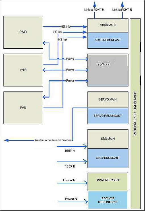
The MEB is based on a redundant sub-assembly architecture and it is devoted to the control of the hyperspectral instrument and to handle, according to the agreed protocols, the bit stream representing the spectral images up to the interface with the spacecraft transmitter. The MEB is composed of:
• SBC (Single Board Computer) – One board embedding nominal and redundant functions with galvanic insulation
• PDM-MEB (Power Distribution Module-Main Electronic Box) – One board embedding nominal and redundant function with galvanic insulation for nominal and redundant supply of the MEB
• PDM-PE (Power Distribution Module-Proximity Electronics) – One board for the supply of the proximity electronics.
• SDAC (Scientific Data Acquisition Board) - One board embedding nominal and redundant functions with galvanic insulation.
• SBC (Servo Control Board) - Two boards, one for nominal and one for redundant, for control of mechanism, heaters and for the read of thermistor.
Because of the central control function of the instrument a very high reliability is required for the operation. Therefore additional redundant boards are foreseen, which are in cold standby redundancy for low power operation. The switch over to the redundant boards will be performed by the spacecraft.
The lossless data compression, based on the CCSDS (Consultative Committee for Space Data Systems) Standard 123, achieves an average compression ratio of 1.6 on hyperspectral data with a dedicated FPGA (Field Programmable Gate Array) on the SDAC board.
The overall dimensions of the MEB are:
• Size: 300 x 270 x 205 mm
• Total mass: 9 kg.
The MEB uses a redundant sub-assembly architecture and is in charge of controlling the PRISMA instrument. The MEB is physically separated from the optical head and from the proximity electronics: it is accommodated inside the bus, fixed on the top plate interface between the spacecraft and the optical head.
The MEB has a mass of 9 kg and a size of 300 mm x 270 mm x 205mm.
Development Status of the PRISMA Payload
• July 2018: The program has successfully completed the System Level CDR and is currently in phase D (qualification and integration).
• October 2015: The most challenging technical aspects of the PRISMA payload have been fully investigated and verified by means of breadboards for an experimental validation: in particular the thermal control system and optomechanical stability of the optical bench have been object of accurate measurements and verifications. The following progresses have been made and documented: (Ref. 28)
- the qualification phase completion of the main subassemblies [detector, heat pipe, main port mechanism, shutter and solar port, ICU (Internal Calibration Unit), calibration sources, coating]
- a successful extended thermal vacuum campaign of PRISMA components (integration tests) so to verify and to optimize the electronic chain from detectors to PE (Proximity Electronics)
- the integration and alignment of optical elements on the optical bench
- the instrument is ready for the final thermal vacuum campaign and calibration characterization.
Ground Segment
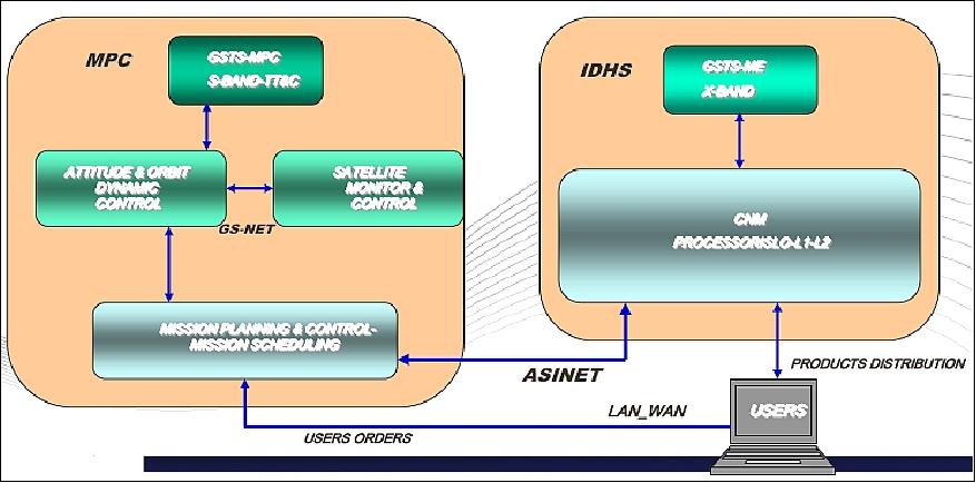
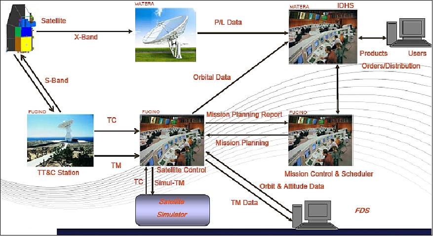
The ground segment of the PRISMA mission includes two main elements (Ref: 10):
• MPC (Mission Planning and Control) in Fucino, Italy. The Fucino station use an S-band antenna to provide telemetry and telecommand for satellite management. It hosts the following subsystems:
- Satellite Control Center (SCC), for monitoring and controlling the satellite
- Flight Dynamics System (FDS) which takes care of orbit/attitude operations
- TT&C Station providing the S-band link service between the satellite and the GS
- Mission Control Center (MCC) providing the mission planning and related tasking sequences generation.
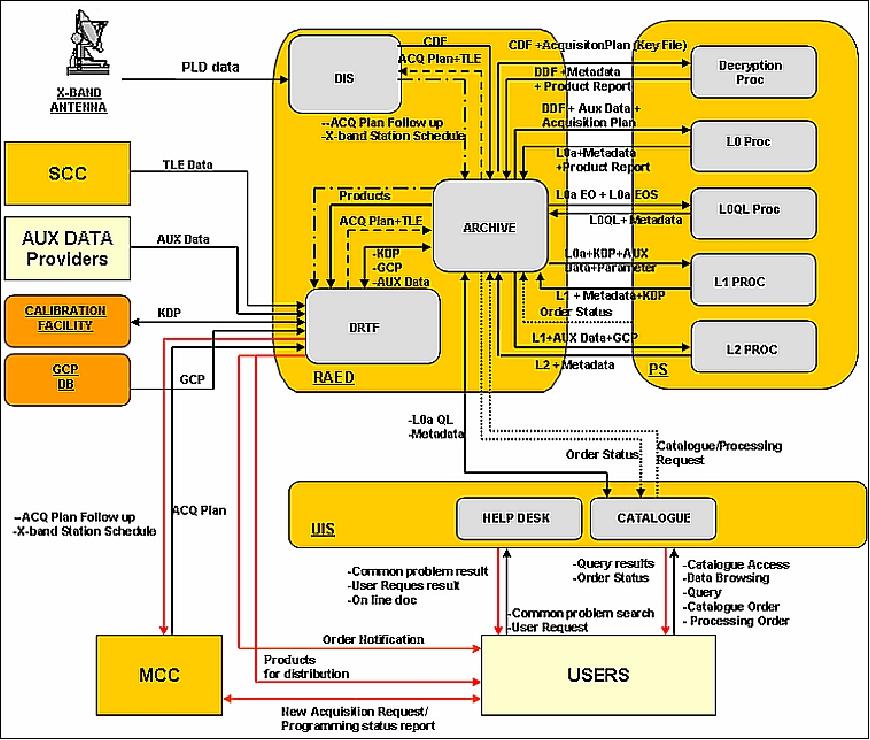
• IDHS (Instrument Data Handling System) in Matera, Italy, part of the CNM (Multimission National Center). Dedicated to imaging data acquisition, processing, archiving and distribution (PRISMA user interface). The IDHS data processing function is devoted to generate Level 0, Level 1 and Level 2 products.
The IDHS and the CNM in Matera are the main facilities in charge of X-band payload data reception, processing and archiving/delivering the PRISMA data and products. The end users can access PRISMA mission data (catalog and new acquisition requests) through a unique web access point named CAS (CNM Access System).
A dedicated communication local network (WAN/LAN) implements the connections between the different GS entities in a secure, reliable and efficient way.
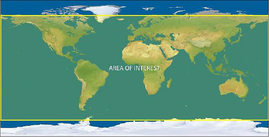
Geographic coverage: The PRISMA system can acquire, downlink and archive images of all hyperspectral/panchromatic channels up to 200,000 km2 daily, in a reference scenario where the targets are scenes (30 km x 30 km each) spatially evenly distributed over the main landmasses of the Primary Area of Interest (Figure 24) accessible by the PRISMA payload, defined as:
- Longitude: in the range 180°W - 180°E
- Latitude: in the range 70°S - 70°N.
PRISMA products and operational modes: The PRISMA mission can operate in two modes. The primary mode of operation is the collection of hyperspectral and panchromatic data from specific individual targets requested by end users, while for the secondary mode the mission will have an established ongoing ‘background' task to acquire imagery such that the satellite and downlink resources are fully used.
The Primary and Background Operational modes can be present simultaneously/alternately during an acquisition plan.
The Primary request can be elementary "Standard" request that will generate a 30 km × 30 km image, identified by its scene center geographical coordinates (Lat, Lon) or "Strip" request that will generate an image 30 km wide and long as multiple of 30 km for max 1800 km along track.
The Users can access the PRISMA system via web to perform the following actions: New User Registration Process, User Login and Operation Processes. The User can submit a new image acquisition requests and/or access the catalogue browser (to search of images already present) to obtain a product.
PRISMA mission products are: 30)
• Level 0 (L0): raw data stream including instrument and satellite ancillary data
• Level 1 (L1): TOA (Top Of Atmosphere) radiometrically and geometrically calibrated HYP and PAN radiance images
• Level 2 (L2): Geolocated and geocoded atmospherically corrected HYP and PAN images, atmospheric constituents maps (aerosols, water vapor, thin cloud optical thickness).
HSIS, User's Opportunity
A Hyper Spectral Image Simulator (HSIS) is included in the PRISMA system, as part of the IDHS Element. The image simulator HSIS aims at allowing the verification of the production chain before its integration in the Processing Subsystem, thanks to its capability of simulating all the relevant knowledge about the instrument, the orbit, the radiation source, the atmosphere and the observed scene.
The HSIS represents a very important opportunity for scientists who want to test and evaluate the performances of the L1 and L2 PRISMA processors. The hyperspectral image simulator for PRISMA mission produces simulated PRISMA-like imagery in the spectral range of interest (0.4-2.5 µm) integrating into a single tool all the relevant knowledge about the instrument, the radiation source, the atmosphere, and the observed scene. 31)
The Image Simulator ingests as input either synthetic or real surface reflectance/radiance images, compatible with PRISMA sensor characteristics. Input radiance and/or reflectance data can be generated starting from synthetic images or from other satellite or airborne hyperspectral radiance images.
References
1) Claudio Galeazzi, Andrea Sacchetti, Andrea Cisbani, Gianni Babini, "The PRISMA Program," Proceedings of IGARSS 2008 (IEEE International Geoscience & Remote Sensing Symposium), Boston, MA, USA, July 6-11, 2008
2) https://www.asi.it/en/earth-science/prisma/
3) Andrea Sacchetti, Claudio Galeazzi, Andrea Cisbani, Gianni Babini, "The Italian precursor of an operational hyperspectral imaging mission," Proceedings of the 7th IAA Symposium on Small Satellites for Earth Observation, Berlin, Germany, May 4-7, 2009, IAA-B7-1102, URL of presentation:[web source no longer available]
4) E. Razzano, G. D. Morea, S. Cipolla, C. Galeazzi, G. N. Varacalli, "Mission Analysis for the PRISMA Earth Observation Satellite," Proceedings of the 7th IAA Symposium on Small Satellites for Earth Observation, Berlin, Germany, May 4-7, 2009, IAA-B7-0216P
5) Cristina Ananasso,Claudio Galeazzi, and the PRISMA project team, "The PRISMA Mission," Second HyspIRI NASA Decadal Survey Mission Science Workshop, Pasadena, CA, USA, Aug. 11-13, 2009, URL: http://hyspiri.jpl.nasa.gov/downloads/2009_Workshop/day3/day3_4._Hyspiri-PRISMA%20presentation.pdf
6) "The PRISMA mission," ASI, Sept. 4, 2009, URL: https://www.asi.it/wp-content/uploads/2020/03/The-PRISMA-mission.pdf
7) Claudio Galeazzi, Paolo Sabatini, Andrea Cisbani, Gianni Babini, "The PRISMA Program," URL: ftp://lenst.det.unifi.it/pub/LenLar/proceedings/2009/kaconf09/data/session_11/11_1.pdf
8) Laura Candela, Roberto Formaro, Rocchina Guarini, Rosa Loizzo, Francesco Longo, Giancario Varacalli, "The PRISMA Mission," Proceedings of the IEEE IGARSS (International Geoscience and Remote Sensing Symposium) Conference, Beijing, China, July 10-15, 2016
9) M. Battilana, F. Longo, G. Varacalli, "PRISMA-1: An agile, high performance AOCS for EO Missions," Proceedings of GNC 2011, 8th International ESA Conference on Guidance, Navigation & Control Systems, Carlsbad (Karlovy Vary), Czech Republic, June 5-10, 2011
10) R. Loizzo, R. Guarini, F. Longo, T. Scopa, R. Formaro, C. Facchinetti, G. Varacalli, "PRISMA: The Italian Hyperspectral Mission," Proceedings of IGARSS (International Geoscience and Remote Sensing Symposium), Valencia, Spain, July 23-27, 2018
11) "OHB's first hyperspectral satellite preparing for launch into space," OHB Press Release, 6 March 2019, URL: https://www.ohb.de/en/news/2019/ohbs-first-hyperspectral
-satellite-preparing-for-launch-into-space/
12) "Processing begins with PRISMA for Arianespace's next Vega launch from the Spaceport," Arianespace, 24 January, 2019, URL: http://www.arianespace.com/mission-update/vv14-prisma-preparations/
13) "Arianespace orbits 600th satellite, the PRISMA Earth observation satellite for the Italian Space Agency," Arianespace, 21 March 2019, URL: http://www.arianespace.com/press-release/arianespace-orbits-600th-
satellite-the-prisma-earth-observation-satellite-for-the-italian-space-agency/
14) "Vega launches Earth observation satellite for Italy," ESA, 22 March 2019, URL: http://m.esa.int/Our_Activities/Space_Transportation/
Vega_launches_Earth_observation_satellite_for_Italy
15) "Flight VV14: New launch date for PRISMA," Arianespace, 12 March 2019, URL: http://www.arianespace.com/press-release/flight-vv14-new-launch-date-for-prisma/
16) Stephen Clark, "Launch Schedule," Spaceflight Now, 29 June 2018, "URL: https://spaceflightnow.com/launch-schedule/
17) "OHB Italia sign contract to launch PRISMA Italian satellite with Arianespace," Space Daily, June 20, 2017, URL: http://www.spacedaily.com/reports/OHB_Italia_on_behalf_of_the_Italian_Space_Agency
_and_Arianespace_sign_contract_to_launch_PRISMA_Italian_satellite_999.html
18) Marco Faraci, Enrico Fossati, Massimo Cosi, Francesco Sarti, Francesco Longo, Claudia Facchinetti, Giancarlo Varacalli, Luigi Ansalone, Leandro Chiarantini Alessandro Chierici, Michele Dami, Emiliano Di Carmine, Davide Fiorini, Roberto Formaro, Lorenzo Giunti, Marco Lastri, Rosa Loizzo, Ettore Lopinto, Marco Meini, Giuseppe Mondello, Ottavio Nannucci, Beatrice Ponticelli, Virginia Schinaia, Enrico Suetta, "The PRISMA payload and products -preliminary results of commissioning phase," Proceedings of the 70th IAC (International Astronautical Congress), Washington DC, USA, 21-25 October 2019, paper: IAC-19,B1,3,2, URL: https://iafastro.directory/iac/proceedings/IAC-19/IAC-
19/B1/3/manuscripts/IAC-19,B1,3,2,x50473.pdf
19) Demetrio Labate, Alessandra Barbis, Alessandro Bini, ndrea Cisbani, Iacopo Ficai Veltroni, Lorenzo Giunti, Paolo Marrucci, Claudio Pasqui, Leonardo Tommasi, "Hyperspectral Instrumentation New Development at Selex Galileo," Proceedings of the 60th IAC (International Astronautical Congress), Daejeon, Korea, Oct. 12-16, 2009, IAC-09.B1.1.10
20) C. Galeazzi, R. Carpentiero, V. De Cosmo, L .Garramone, F. Longo, E. Lopinto, G. Varacalli, "The PRISMA System an Pan/Hyp Instrument," Proceedings of the 6th EARSeL Imaging Spectroscopy SIG (Special Interest Group) Workshop, March 16-18, 2009, Tel Aviv, Israel, URL: https://web.archive.org/web/20130928030805/http://www.earsel6th.tau.ac.il/~earsel6/CD/PDF/earsel-PROCEEDINGS/3020%20Galeazzi.pdf
21) D. Labate, M. Ceccherini, A. Cisbani, V. De Cosmo, C. Galeazzi, L. Giunti, M. Melozzi, S. Pieraccini, M. Stagi, "The PRISMA Payload Optomechanical Design - A High Performance Instrument for a new Hyperspectral Mission," Proceedings of the 59th IAC (International Astronautical Congress), Glasgow, Scotland, UK, Sept. 29 to Oct. 3, 2008, IAC-08-B1.3.3
22) G. Preti, A. Cisbani , V. De Cosmo , C. Galeazzi , D. Labate , M. Melozzi, "Hyperspectral Instruments for Earth Observation," Proceedings of the 7th ICSO (International Conference on Space Optics) 2008, Toulouse, France, Oct. 14-17, 2008
23) Alessandro Barducci, Stefano Baronti, Roberto Carlà, Donatella Guzzi, Cinzia Lastri, Paolo Marcoionni, Vanni Nardino, Ivan Pippi, Andrea Garzelli, Luciano Alparone, "Advanced Methodologies for the Analysis, Integration and Optimization of Prisma Mission Products," Proceedings of the Hyperspectral Workshop 2010, Frascati, Italy, M;arch 17-19, 2010, ESA SP-683
24) Paolo Marrucci, Michele Dami, Lorenzo Giunti,Beatrice Ponticelli, Enrico Fossati, "PRISMA Payload," Proceedings of the Hyperspectral Workshop 2010, Frascati, Italy, March 17-19, 2010, ESA SP-683
25) Marco Meini, Fabrizio Battazza, Roberto Formaro, Michele Dami, Enrico Fossati, Lorenzo Giunti, "Hyperspectral Payload for PRISMA Mission," Proceedings of the 4S (Small Satellites Systems and Services) Symposium, Portoroz, Slovenia, June 4-8, 2012
26) Mario Cosmo, Fabrizio Battazza, Francesco Caltagirone, Fabio Covello, Giuseppe Francesco De Luca, Roberto Formaro, Francesco Longo, Giancarlo Natale Varacalli, "The future EO ASI missions are based on SAR and hyperspectral sensors," Proceedings of the 63rd IAC (International Astronautical Congress), Naples, Italy, Oct. 1-5, 2012, paper: IAC-12-B1.2.8
27) G. C. Caprini, M. Ceccherini, M. Brotini, A. Bini, R. Corsini, L. Gasparini, F. Battazza, R. Formaro, "Main Port Mechanism for PRISMA," Proceedings of the 15th ESMATS (European Space Mechanisms and Tribology Symposium) 2013, Noordwijk, The Netherlands, Sept. 25-27, 2013, ESA, SP-718, URL: http://www.esmats.eu/esmatspapers/pastpapers/pdfs/2013/caprini.pdf
28) Marco Meini, Enrico Fossati, Lorenzo Giunti, Marco Molina, Roberto Formaro, Francesco Longo, Giancarlo Varacalli, "The PRISMA Mission Hyperspectral Payload," Proceedings of the 66th International Astronautical Congress (IAC 2015), Jerusalem, Israel, Oct.12-16, 2015, paper: IAC-15-B1.2.7
29) S. Pignatti, F. Longo, "Soil spectral information in the era of commercial hyperspectral sensor in orbit: PRISMA Project," GEO-CRADLE Workshop & Project Meeting , 16-17 November 2016, Limassol, Cyprus, URL: http://geocradle.eu/wp-content/uploads/2016/11/Soil-Spectral-info-PRISMA-project-CNR-IMAA-1.pdf
30) R. Guarini, R. Loizzo, C. Facchinetti, F. Longo, B. Ponticelli, M. Faraci, M. Dami, M. Cosi, L. Amoruso, V. De Pasquale, N. Taggio, F. Santoro, P. Colandrea, E. Miotti, W. Di Nicolantonio, "PRISMA Hyperspectral Mission Products," Proceedings of IGARSS (International Geoscience and Remote Sensing Symposium), Valencia, Spain, July 23-27, 2018
31) R Guarini, R. Loizzo, F. Longo, S. Mari, G. Varacalli, P. Colandrea, S. Signorile, M. L. Magliozzi, C. Avolio, M. Zavagli, M. Costantini, L. Giunti, E. Fossati, "Focus on PRISMA Hyperspectral Image Simulator:functionalities and applications," Workshop on Simulation for European Space Programs (SESP), Noordwijk, The Netherlands, 28-30 March 2017
Spacecraft Launch Mission Status Sensor Complement Ground Segment References Back to Top