CUTE-17+APD-2
Non-EO
Quick facts
Overview
| Mission type | Non-EO |
CUTE-1.7+APD-2 (Cubical Tokyo Tech Engineering Satellite-1.7)
CUTE-1.7+APD-2 is an improved successor mission of the CUTE-I nanosatellite mission (launch June 30, 2003) and the Cute-1.7+APD mission (launch Feb. 21, 2006, UTC), developed and built by the second generation of students of the Tokyo Institute of Technology (TITech) Matunaga Laboratory for Space System (LSS). The ADP-2 (Avalanche Photodiode-2) sensor module was developed by the Tokyo Institute of Technology Kawai Laboratory. The design of CUTE-1.7+APD-2 started in April 2006. 1) 2) 3) 4)
The Cute-1.7+APD-2 project has two objectives: 5)
1) The first objective is to facilitate future microsatellite development projects by demonstrating a new design methodology. The methodology,aiming toward rapid and low-cost development,includes proactive use of high performance and low-cost commercial devices in orbit. The Cute-1.7+APD series are equipped with several COTS (Commercial Off-The-Shelf) devices including widely used PDAs (Personal Digital Assistants) as their OBC (On-Board Computer) and amateur radio transceivers as communication devices.
2) The second objective is to provide flight experiment opportunities to spac engineering researchers and students by developing a highly versatile satellite. To this aim, this satellite contains an engineering mission shared with researchers in the field of control engineering. On-board devices for attitude determination and control such as three magnetic torquers and a software upload function, which can update software inside the PDAs from the ground, enable on-orbit experiments of advanced attitude control algorithms. In addition, the Cute-1.7 series was designed to provide other researchers an opportunity to demonstrate their devices using as simple interface between the satellite bus system and their own devices. A scientific observation device, APD (Avalanche Photo Diode) sensor, is used in the Cute-1.7+APD series to demonstrate it on orbit.
Spacecraft:
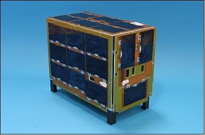
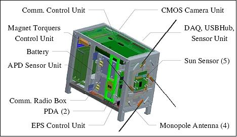
The nanosatellite features a number of improvements based on experiences gained from its predecessor model, CUTE-1.7+APD. In particular, the spacecraft structure was redesigned to increase the solar cell surface area for enhanced power generation. The CUTE-1.7+APD-2 nanosatellite has dimensions of 220 mm x 180 mm x 115 mm and a total mass of ~ 3 kg. The structural change made to this (larger than standard) spacecraft model provided simply more freedom to handle things and contributed to the assembly and integration functions. 6)
The EPS (Electric Power Subsystem) uses high efficiency GaAs solar cells which are surface-mounted on all panels of the spacecraft. The Li-ion battery (NEC-Tokin) with four cells provides a nominal voltage of 3.8 V and a storage capacity of 1130 mAh/cell. An average power of 4 W is provided.
Another modification was to increase the power generation of the small satellite. The orbital operation of the former satellite showed relatively low power compared to previous estimates,which affected the satellite’s operation procedures.The power generation is enhanced by increasing the dimension of the satellite. As a result, mean generated power is increased from 3 to 4 W.
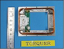
The ADCS (Attitude Determination and Control Subsystem) is again experimental for advanced magnetic torque control demonstrations, having the capability of uploading control software. All actuation services (3-axis stabilization, detumbling, and spin-up) are provided by magnetic torquers (3 magnetic torquers in orthogonal configuration).
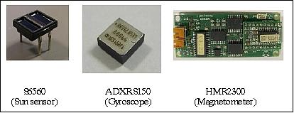
Attitude sensing is provided by a gyroscope (ADXRS150 of Analog Devices), a 3-axis magnetometer (HMR2300 of Honeywell), a sun sensor (S6560 of Hamamatsu Photonics, Japan), and an Earth sensor (Ref. 6).
- The S6560 sun sensor has two photo-diodes per unit whereby a difference of currents between them indicates, via a known correlation, the incident angle of light. They, therefore, were used as sun sensors. Two units each are mounted on five of the sides except for the top side of the satellite. The sensor’s coverage is 84% of the whole sky.
- The gyroscope can measure an angular velocity around a single axis and output the measured value as analog data. This analog data is acquired by an A/D converter of a DAQ (Data Acquisition Device) controller. The temperature of the gyroscope is also determinable and enables appropriate calibration of the instrument to compensate for temperature dependency.
- The HMR2300 magnetometer consists of Honeywell’s subcomponent of magnetic sensors (HMC1001 and HMC1002) and a digital interface. A performance test was conducted using a magnetic shield facility with the support of JAXA.
The satellite has four algorithms for attitude determination: QUEST (Quaternion Estimation), REQUEST(Recrusive QUEST), EKF (Extended Kalman Filter) and UF (Unscented Kalman Filter). The use of a high-performance PDA enables a realtime attitude determination of the satellite using these advanced algorithms. An attitude estimation will also be done on the ground by recalculating using the sensor data from the satellite and its result will be used to confirm the result of on-orbit attitude determination experiment by comparing them.
An update was made to the ADCS to provide the attitude sensor data with a time stamp and in parallel to better facilitate the function of attitude determination. In addition, the output torque of the actuator was increased. The change on the structural design and measurement of the residual magnetic field in the satellite resulted in magnet torquer improvements. The torque was increased by dividing a coil into three and connecting them in parallel, which in turn increases the current supply to the magnet torquers.
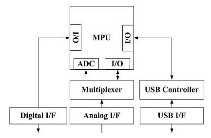
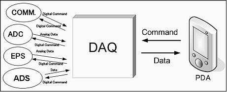
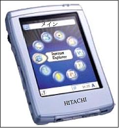
A PDA (Personal Digital Assistant) device of Hitachi is being used as OBC (Onboard Computer). It performs all onboard functions and calculates also the attitude of the spacecraft from the ADCS attitude sensor data. A special DAQ (Data Acquisition Subsystem) was developed by TITech, since a PDA has only a USB interface and lacks such functions as ADC (Analog Digital Conversion), DIO (Digital Input Output) port operation, and PWM (Pulse Width Modulation) operations support. Note: The MPU (Main Processing Unit) simply consists of two PDAs.
Manufacturer, Model | Hitachi, NPD-20JWL (C&DHS) |
Size, mass | 70 mm x 100 mm x 5 mm, 100 g |
CPU | ARV4I 400 MHz |
OS (operating System) | Microsoft Windows, CE.NET |
RAM, Flash memory | 32 Mbyte, SD Card 128 (Mbyte) |
Interfaces | USB, MMC/SD Card Slot |
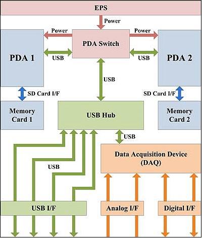
C&DHS (Command and Data Handling Subsystem): The C&DHS (Figure 8) consists of a redundant PDA as the main computer, the DAQ and the USB Hub to expand the interface capability of PDA, and a PDA Switch which oversees the priorities for the working PDA selection on error detection.
Radiation protection circuit update for the CUTE-1.7+APD-2 mission: The objective is to prevent the PDA from halting due to a SEL (Single Event Latchup) or a SEU (Single Event Upset). The radiation protection system for the PDA consists of a double watchdog and over-current protection. The design assumption is that there is only a single point affected by radiation over the IC at any time. - In a ground test conducted, the watchdog IC demonstrated an effective tolerance to a simulated current latchup event (i.e., increase in current) generally experienced by cosmic induced radiation.
Note: The cause in premature malfunctioning of the predecessor satellite (CUTE-1.7+APD) can only be explained that it experienced an SEL (Single Event Latchup) in the communication microcomputer (PDA) which resulted in a considerable degradation of its functionality and prevented a continuation of the nominal mission.
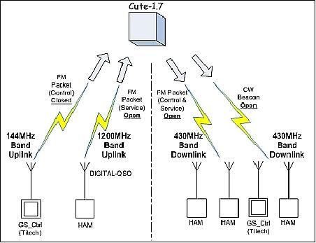
RF communications: Use of IARU (International Amateur Radio Union) standards and guidelines. CUTE-1.7+APD-2 uses the FM packet transmission in downlink and uplink with the AX.25 protocol (total of 4 communication channels): a) a UHF (437.475 MHz) downlink, and b) the L-band (1267.6 MHz) in uplink. In addition, a CW (Continuous Wave) beacon in UHF (437.275 MHz) is being used. The sharing of the downlink with the amateur community, ARS (Amateur Radio Service), increases the data acquisition capability of the spacecraft considerably. 7)
In addition, Cute-1.7+APD-2 has another protocol called SRLL,which is TITech’s original protocol, and GMSK modulation. The SRLL protocol has an error correction function and it makes the protocol robust and suitable for satellite communication. The data rate of the GMSK modulation is 8 times faster than that of the AFSK modulation. Both uplink and downlink using SRLL and GMSK succeeded in orbital operation and these methods led to faster communications (Ref. 5).
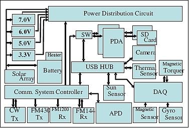
Figure 9 shows the functional diagram of Cute-1.7 +APD-2. Thirteen blocks out of the total thirty ones employ commercial products including PDAs, memory cards, USB (Universal Serial Bus) hubs, digital cameras and handheld amateur radio transceivers. Most subcomponents are connected to a PDA through the USB interface that enables plug and play. The connectivity contributes to designing each subcomponent as a module and expanding versatility of this satellite by providing easy connection to various mission devices (Ref. 6).
Communication channel | Frequency | Modulation | Protocol | Transceivers |
Uplink of project | 144 MHz | AFSK 1200bit/s | AX.25/SRLL, DTMF | DJ-C5 |
Uplink | 1200 MHz band | GMSK 9600bit/s |
| TH-59 |
Telemetry | 430 MHz band | AFSK 1200bit/s |
| DJ-C5 |
Beacon | 430 MHz band |
|
|
|
Launch: CUTE-1.7+APD-2 was launched on April 28, 2008 as a secondary payload on a PSLV-C9 launch vehicle of ISRO from SDSC (Satish Dhawan Space Centre), Sriharikota, India. The primary payload on this multi-satellite flight was CartoSat-2A.
The launch of secondary payloads has been shared by IMS-1 (Indian Microsatellite-1) of ISRO with the following CubeSats or nanosatellites:
- CanX-2 of UTIAS/SFL, Toronto, Canada
- AAUSat-2 of Aalborg University, Denmark
- COMPASS-1 of the University of Applied Science, Aachen, Germany
- Delfi-C3 of the Technical University of Delft, The Netherlands
- SEEDS-2 of Nihon University, Japan
- CUTE-1.7+APD-2 CubeSat of the Tokyo Institute of Technology
- NTS (Nanosatellite Tracking of Ships) of Com Dev / UTIAS/SFL, Toronto, Canada
- Rubin-8-AIS an experimental space technology mission of OHB-System, Bremen, Germany.
Deployment/separation system: The modified separation system CSS (CUTE Separation System) of TITech was used (same system as flown on the CUTE-1.7+APD mission). CUTE-1.7+APD-2 was separated from the last rocket stage, after the separation of the CartoSat-2A primary spacecraft.
Note: The CUTE-1.7-APD-2 spacecraft was not furnished with an electrodynamics tether system like its predecessor (for deployment at the end of the mission).
Orbit: Sun-synchronous circular orbit, altitude = 635 km, inclination = 97.94º, local crossing time on the descending node at 9:30 hours, period = 97.2 minutes.
Mission status:
• The CUTE-1.7+APD-2 nanosatellite is operational in 2014 (6 years on orbit as of April 28, 2014), although there is a tendency toward aging. 8)
• The CUTE-1.7+APD-2 nanosatellite is still operational in 2012 (with nearly 4 years on orbit in April 2012). The mission is now conducted in the following way: 9)
- The instrument data are transmitted by using the amateur band.
- Science mission: observation of charged particle distribution using the APD (Avalanche Photo Diodes).
• In 2011, the CUTE-1.7+APD-2 nanosatellite is operating nominally (more than 3 years on orbit). 10)
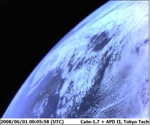
• Photos have been taken by the satellite as shown in Figure 13. The accurate attitude of the satellite can be known from the imagery. The nanosatellite can also take a 20 frame movie with a rate of 15 frame/s.
• The APD module was activated on May 6, 2008, and the first scientific observation began during the first contact pass over TITech on May 7. Through two short¿term observations (station contact pass), normal APD behavior was confirmed. Longer APD observations were subsequently conducted for 12 or 24 h (typically four times monthly), with APD data being transmitted to the ground station. 12)
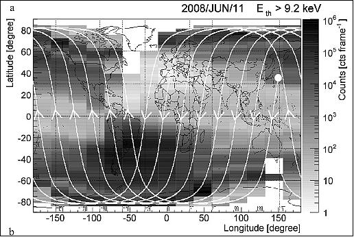
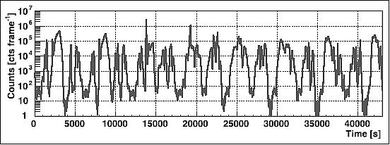
Legend to Figures 14 and 15: The lines in Figure 14 represent the trajectory of the Cute¿1.7+APD-2, while the circle denotes the starting point of observation (t = 0 in Figure 15).
• The nanosatellite became operational in May 2008. Attitude experiments, camera missions, APD observations and communication experiments have been successfully conducted (Ref. 6). The initial operation phase continued for more than a month, during which such basic functions as power generation and communications were carefully tested.
• Contact with the nanosatellite was established shortly after launch and deployment. Thereafter, the spacecraft entered the checkout phase to test the basic functional performance of all subsystems.
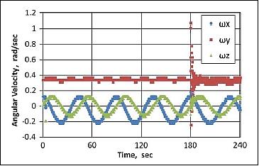
• When the satellite separated from the launch vehicle and activated, it acquired gyro data for4minutes with10 Hz resolution and stored this inside FRAMs. The gyro data indicated the initial rotation of the satellite. After the separation, the satellite rotated at a slow speed, 0.4 rad/s as shown in Figure 16. - Antenna deployment was conducted at 3 minutes after separation and the rotation of the satellite indicated the deployment was a success.
Experiment complement/demonstrations:
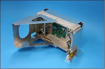
APD (Avalanche Photodiode) detector:
The APD experiment was developed by the Kawai Laboratory of the Physics Department of TITech. The objective is to observe the low energy charged particle density distribution in LEO (Low Earth Orbit). APD is very small in size, exhibits a low-power consumption, and provides a high-speed response.
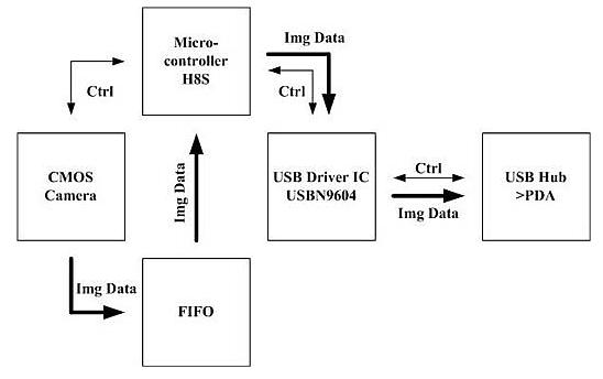
CMOS camera:
A compact CMOS camera module which is designed for a mobile phone. The objective is to take occasional snapshot imagery of Earth and to use the camera for onboard event verification. The camera module is controlled by a microcontroller (Renesas' H8) with intermediate data storage in a FIFO (First Input, First Output) memory before it is sent to the PDA via USB.
The CMOS imaging sensor provides the following specification:
• 1/3 inch, CMOS camera module, progressive scan
• Very low power consumption for use in a cell-phone
• FOV = 58º; depth of field: 120 cm; f/No: 2.8
• Control: I2C I/F
• Data type: UYVY, 8 bit
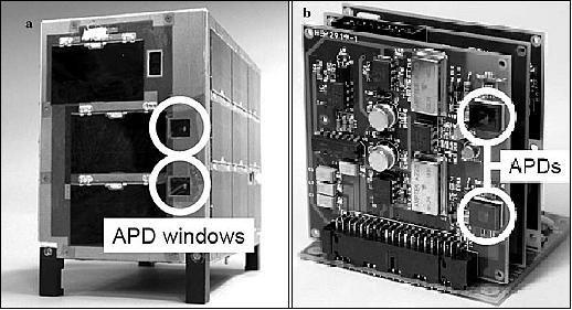
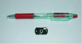
Legend to Figure 18: a) The white circles show the APD windows for particle measurements. The APDs are embedded in 1 cm depth from the surface windows. (b) The flight model of the APD module. The APD detectors (S8664¿55, Hamamatsu), 5 mm x 5 mm each, are attached in the upper and lower right corners of a printed circuit board as shown in Figure 18b (white circles). Each APD sensor provides a FOV of ~ 0.9 radian.
1) http://lss.mes.titech.ac.jp/ssp/cute1.7/index_e.html
2) http://lss.mes.titech.ac.jp/ssp/cute1.7/subsystems_e.html
3) K. Fujiwara, K. Omagari, T. Iljic, S. Masumoto, Y. Konda, T. Yamanaka, Y. Tanaka, M. Maeno, T. Ueno, H.i Ashida, J. Nishida, T. Ikeda, S. Matunaga, ”Tokyo Tech Nano-Satellite Cute-1.7+APD Flight Operation Results and the Succeeding Satellite,” The 17th IFAC Symposium on Automatic Control in Aerospace, Toulouse, France, June 25-29, 2007, URL (paper): http://lss.mes.titech.ac.jp/ssp/cute1.7/paper/aca2007.pdf, URL (presentation): http://lss.mes.titech.ac.jp/ssp/cute1.7/paper/aca2007_p.pdf
4) H. Ashida, J. Nishida, K. Omagari, K. Fujiwara, Y. Konda, T. Yamanaka, Y. Tanaka, M. Maeno, K. Fujihashi, S. Inagawa, Y. Miura, S.Matunaga, ”Flight Model Development of Tokyo Tech Nano-Satellite Cute-1.7 + APD II,” Proceedings of the 26th International Symposium on Space Technology and Science (ISTS 2008), Hamamatsu, Japan, June 1-8, 2008, paper: 2008-f-22
5) Hiroki Ashida, Kota Fujihashi, Shinichi Inagawa, Yoshiyuki Miura, Kuniyuki Omagari, Naoki Miyashita, Saburo Matunaga, Takahiro Toizumi, Jun Kataoka, Nobuyuki Kawai, “Design of Tokyo Tech nano-satellite Cute-1.7+APD II and its operation,” Acta Astronautica, Vol. 66, Issues 9–10, May–June 2010, pp. 1412–1424
6) Hiroki Ashida, Kota Fujihashi, Shinichi Inagawa, Yoshiyuki Miura, Kuniyuki Omagari, Yasumi Konda, Naoki Miyashita, Saburo Matunaga, "Design of Tokyo Tech Nano-Satellite Cute-1.7 + APD II and its Operation," 59th IAC (International Astronautical Congress), Glasgow, UK, September 29-October 3, 2008, IAC-08-B4.6.A4, URL: http://lss.mes.titech.ac.jp/ssp/cute1.7/paper/iac2008.pdf
7) “Cute-1.7 + APD II Project - Amateur Radio Service, URL: http://lss.mes.titech.ac.jp/ssp/cute1.7/amateur_service_e.html
8) Information provided by Saburo Matunaga of Tokyo Institute of Technology, Tokyo, Japan.
9) Information provided by Shota Morii of Tokyo Institute of Technology, Tokyo, Japan.
10) Saburo Matsunaga, “The challenge for ultra-small satellites - aiming at great innovation in space science,” URL: http://www.isas.jaxa.jp/e/forefront/2011/matsunaga/02.shtml
11) Saburo Matsunaga, “Cute-1.7 + APD II, Tokyo Institute of Technology, Japan,” APRSAF (Asia-Pacific Regional Agency Forum, Hanoi, Vietnam, Dec. 9-12, 2008
12) J. Kataoka, T. Toizumi, T. Nakamori, Y. Yatsu, Y. Tsubuku, Y. Kuramoto, T. Enomoto, R. Usui, N. Kawai, H. Ashida, K. Omagari, K. Fujihashi, S. Inagawa, Y. Miura, Y. Konda, N. Miyashita, S. Matsunaga, Y. Ishikawa, Y. Matsunaga, N. Kawabata, “In-orbit performance of avalanche photodiode as radiation detector on board the picosatellite Cute-1.7+APD II,” Journal of Geophysical Research, Vol. 115, A05204, doi:10.1029/2009JA014699, 2010, URL: http://www.agu.org/pubs/current/si/links/2009JA014699.pdf
The information compiled and edited in this article was provided by Herbert J. Kramer from his documentation of: ”Observation of the Earth and Its Environment: Survey of Missions and Sensors” (Springer Verlag) as well as many other sources after the publication of the 4th edition in 2002. - Comments and corrections to this article are always welcome for further updates.