CubeSTAR (CubeSat Space Technology And Research center)
EO
Quick facts
Overview
| Mission type | EO |
CubeSTAR (CubeSat Space Technology And Research center)
CubeSTAR is a Norwegian satellite project conducted at the University of Oslo (UiO) as a collaboration between the Space and Plasma Physics research group and the Electronics department. The purpose of the project is to perform a technology demonstration of a new patented instrument; the multiple-Needle-Langmuir Probe (m-NLP). The instrument is designed to be able to perform electron density measurements with high spatial resolution.
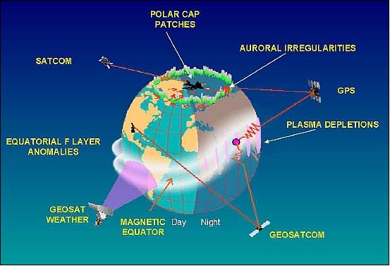
During solar storms, turbulent electron clouds are formed in the ionosphere, causing strong coherent backscatter echos and scintillations in the ionosphere above the polar regions. The phenomenon of electron clouds are far from fully understood. Research in this area gives us the knowledge that we can later use to notify space weather, and to improve equipment such as GPS receivers. CubeSTAR will measure and quantify the structures in the electron clouds and improve the resolution 2000-fold, from today’s seven kilometers down to the meter level. 1) 2)
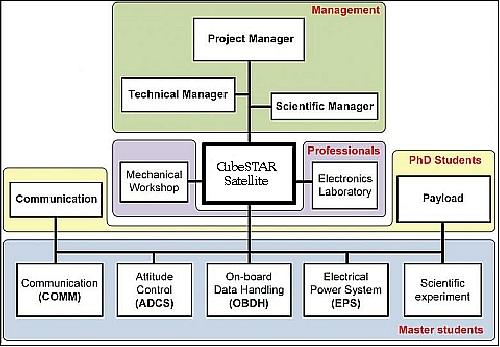
The CubeSTAR project is motivated by both academic and scientific goals. The academic objective is to recruit students to the space science and technology sector. Students are actively involved in the project through graduate theses, participation in international conferences and other activities. This allows the students to take part in a real space mission.
The scientific goal of the project is to perform a technology demonstration of a novel instrument developed by the University of Oslo. The instrument will measure electron density structures with a spatial resolution previously thought not possible. The instrument has been verified through testing in laboratory and on flights with sounding rockets. The next step is to perform proof of concept in orbit; the CubeSTAR mission will serve as a platform to accomplish this goal.
The project is partly funded by NSC (Norwegian Space Center), through ANSAT (Norwegian Student Satellite Program), and NAROM (Norwegian Center for Space-related Education), and by industry. 3) 4)
Spacecraft
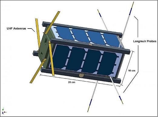
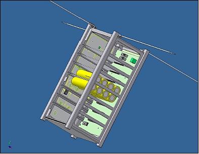
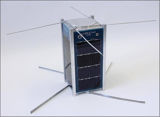
A 2U CubeSat form factor is being used for the spacecraft design developed by students of the University of Oslo. The nanosatellite has a size of 20 cm x 10 cm x 10 cm and a mass of ≤ 2kg. One of the major goals for the project is to build and develop most of the systems in house. This introduces several interesting masters projects that together will have a final goal. The satellite is built and developed by university students along with the electronics lab and the mechanical workshop which will provide the satellite structure and support the students with production of the electronic systems. 5) 6) 7)
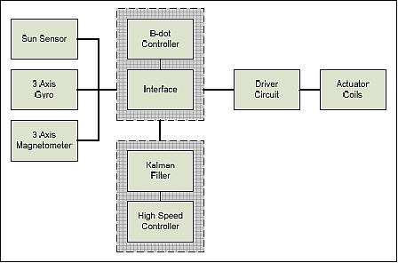
ADCS (Attitude Determination and Control Subsystem): The nanosatellite is 3-axis stabilized. The requirements call for for an attitude pointing control of < ±10º along the pitch and yaw axis to perform undisturbed scientific measurements. Attitude sensing is provided sun sensors, gyroscopes (3 axes) and magnetometers (3 axes).Attitude determination is performed using a simplified Kalman filter to process the sensor outputs using a high speed controller to perform the calculations.
Attitude control is performed using actuator coils. Three coils (magnetorquers) are used to control the attitude, one for each axis. The magnetorquers generates a magnetic field that interacts with the Earth's magnetic field and creates a force that is used to stabilize the satellite.
Detumbling: Detumbling is the process of stabilizing the angular rate of the satellite after orbital insertion. The system uses a B-dot algorithm to detumble. The principle of the B-dot algorithm is to reduce and minimize the derivative of the angular rate. The B-dot controller uses magnetometers to derive the angular rates and manipulate the actuator coils to reduce the angular rate.
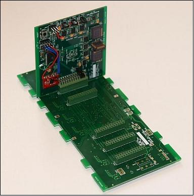
Inner structure of CubeSTAR: The internal subsystems are built as electronic cards, which can be inserted into the satellite structure and connected to the satellite electrically through bus connectors mounted on a backbone bus card. The backbone bus card interfaces the subsystems through an internal bus, providing a power bus, signal lines and an I2C communication bus for the internal systems to communicate with each other.
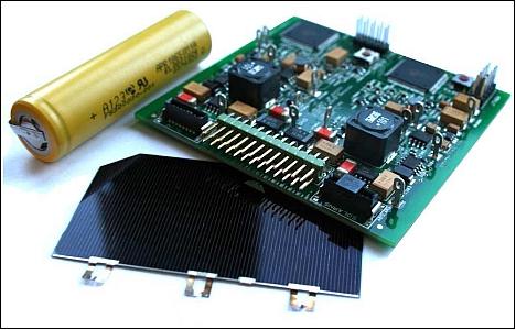
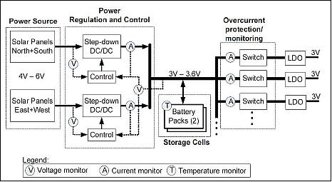
EPS (Electric Power Subsystem): Use of UTJ (Ultra Triple Junction) solar cells of Spectrolab with an efficiency of ~28%. The average power generation during the sunlit portion of the orbit is ~4W. The power from the solar panels is regulated using a MPPT (Maximum Power Point Tracker). The regulator monitors the I-V curve of the solar panels and converts the voltage from the solar panels down to an appropriate charging voltage for the batteries. Two 4.4 Ah LiFePO4 (lithium iron phosphate) battery packs from A123 Systems Inc. are chosen for the mission. These batteries were selected due to their thermal and chemical stability compared to lithium-ion batteries. The drawback of LiFePO4 batteries is that they have somewhat lower energy density than conventional lithium-ion batteries.
Power bus: The EPS supplies a constant 3 V bus to the satellite subsystems. The bus is voltage regulated, with current limiting sensors to protect the batteries from abuse by the subsystems. It was chosen for this mission to only provide a 3 V bus because the discharge voltage for the LiFePO4 batteries is ~3.25 V.
OBC (On-Board Controller): Information will be provided when available.
RF communications: The TT&C (Telemetry, Tracking and Command Subsystem) operates in the UHF amateur satellite band (435-438 MHz), operating in a 25 kHz channel. The system has two radio links, a high-speed link and a low-speed link..
The high-speed link is a half duplex channel, capable of transmitting baud rates between 600 - 19200 baud, using the AX.25 packet protocol and the GFSK (Gaussian Frequency Shift Keying) modulation scheme. The AX.25 packet protocol is a well defined open standard used for transferring data in amateur radio networks. This protocol was selected because one of the requirements for using the amateur satellite bands is to use an open communication protocol.
The link is designed for compatibility with GENSO (Global Educational Network for Satellite Operations). GENSO is a ground station network intended for use by the amateur satellite community. The network connects amateur ground station throughout the world through the internet, allowing amateur satellite teams to communicate with their satellite when the satellite is out of range from the local ground station.
The low-speed link is a simplex channel (beacon), which periodically sends a tracking signal to allow ground station operators to detect and track the satellite. The link uses a CW (Continuous Wave) modulation scheme, transmitting 12-48 Words Per Minute (WPM) using the Morse code as data protocol to simplify the decoding process. The signal will consist of a predefined ID flag and housekeeping data (internal temperatures, battery condition, etc.).
Launch
A launch of CubeSTAR as a secondary payload is planned for 2013 or early 2014. Launch arrangements are in progress.
Orbit: A LEO near polar orbit is needed.
Sensor Complement
m-NLP (multiple-Needle Langmuir Probe)
A novel miniature Langmuir probe system for the determination of absolute electron density in ionospheric plasma has been developed at the University of Oslo (UiO). The system was successfully flown on the ICI-2 (Investigation of Cusp Irregularities-2) sounding rocket payload launched from the Andoya Rocket Range on December 5, 2008. In addition, the concept has been verified in ESA's plasma chamber in April 2008.
A low-power version, m-NLP, will be adapted to the CubeSTAR project to be the scientific payload onboard the satellite. Previous Langmuir probe systems have had a spatial resolution in the range of several km, while the multi-Needle Langmuir Probe system achieves a spatial resolution down to sub-meter scale.
The system comprises four cylindrical probes of cylindrical shape with a diameter of 0.5 mm and a length of about 25 mm. Each probe is being operated at a different fixed bias voltage in the electron saturation region. Calculation of the electron density will be done on-board the spacecraft in an Altera Cyclone IV FPGA (Floating Point Gate Array), which also will handle the calculation of attitude determination and the control for other subsystems.8) 9) 10)
Design advantages of the instrument:
• Debye sheet effects can be ignored due to the small radius of the probe
• Fixed bias voltage allows for sampling rates up to 9 kHz
• Differential measurements remove the need for electron temperature (Te)
• Electron density (Ne) becomes proportional to the electron current (Ie)
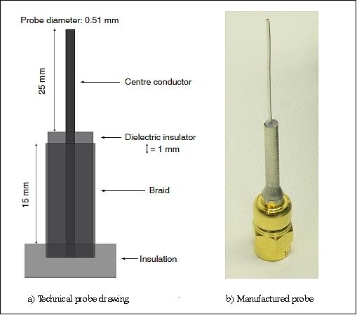
Needle probes: The needle probes needed to have a very small diameter (about 0.5 mm), and have a sufficient mechanical strength to withstand heavy vibrations during launch. In order to reduce sheath effects, it is desirable to have the probes as small as possible, about 1/10 of the Debye shielding length. For prototyping, several semi-rigid coax cables of the probes were tested.
The prototypes were made by using a scalpel to strip the coax cable, according to Figure 11. The center conductor of the coax cable, with a length of 25 mm, works as the cylindrical probe. The insulation on the remaining 15 mm of the braid was removed as well, in order to avoid charging of insulation material close to the probe. A very short insulation area was kept after the braid, in order to avoid a short-circuit between the braid and the center conductor. Other solutions were considered, but these made it inconvenient to get a good method for mechanical mounting and electrical contact. The solution with the semi-rigid coax cable was therefore chosen for its advantages for in-house production and short production time. The final decision was to use the Habia Flexiform 405 FJ.
Overall length | 40 mm |
Braid length | 15 mm |
Probe length | 25 mm |
Probe diameter | 0.51 mm |
Impedance | 50 Ω |
Center conductor | silver-plated copper-clad steel wire |
Dielectric | solid extruded polytetrafluoroethylene (PTFE) |
Braid / shield | tin-soaked copper braid, 100% coverage |
Maximum bias voltage | ~1500 V |
Connector | Suhner SMC |
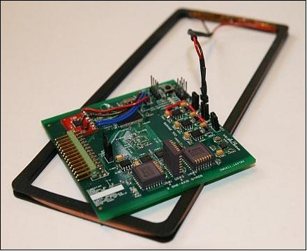
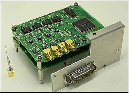
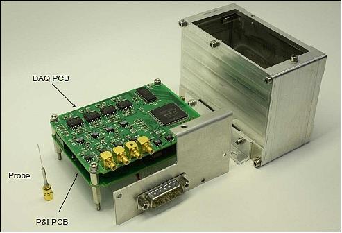
Electrical design of m-NPL: The m-NLP instrument contains two four-layer PCBs (Printed Circuit Boards); one DAQ (Data Acquisition Card) and one power/interface card. The DAQ card’s front-end has four current measurement channels, with current-to-voltage converters, differential amplifiers, passive RC-filters and programmable 8th order elliptic anti-aliasing filters. The analog signals are digitalized in a 16 bit ADC (Analog-to-Digital Converter). A CPLD (Complex Programmable Logic Device) contains all the digital control logic of the instrument. The power/interface card performs voltage regulation and contains the communication interface to the rocket encoder. The two PCBs are connected together with card-to-card connectors made of two gold plated pin rows and mating connectors, giving a spacing of about 10 mm between the PCBs. Components are mainly SMDs (Surface Mounted Devices). They are smaller than hole mounted components and could contribute to lower noise a high frequencies.
Some background on m-NPL measurements: In the northern regions the problem area is the auroral oval, and inside the entire polar cap, but the most important area of global interest is the equatorial region. Here the perturbations in the ionospheric plasma is caused by the force of gravity, instead of the force from the solar wind as in the polar regions.
The global satellite communication (satcom) outage regions can be seen in Figure 13. In order to obtain a sufficient spatial resolution and a better understanding of ionospheric radio wave disturbances, in-situ measurements of the electron density in the space plasma have to be conducted. Langmuir probes are the best instrument for such measurements. To resolve the finest thinkable structures found in ionospheric plasma, limited by the electron gyro radius, a new high-speed sampling system was needed. Such a system can in a long perspective be of use in a global satellite network, mapping the structures and perturbations in the ionospheric plasma around the globe. This can result in a contribution to a space weather forecast for positioning and communication satellites. They suffer from scintillation (amplitude and phase distortion) of radio waves when the activity in the solar wind is high.
Ground Segment
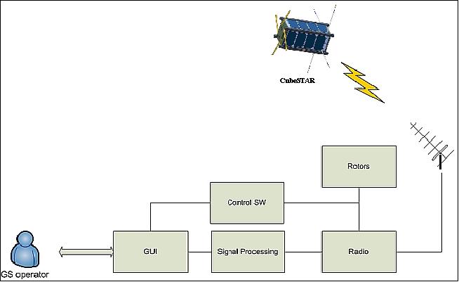
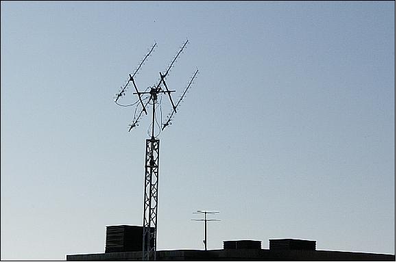
The CubeSTAR ground station has been constructed, using the hardware components recommended by GENSO. The antenna rig is comprised of four UHF Yagi antennas and two rotors which make it possible to change the elevation and azimuth angles. The antenna rig is situated on the roof of the faculty building of UiO.
The ICOM-910H radio is used to receive and transmit RF signals. The hardware (i.e. rotor and radio) is controlled through the Ham Radio Deluxe (HRD) software package. The program allows for automatic tracking of the satellite and compensation of the Doppler shift in the radio signal. A custom LabView application is employed to perform de-/modulation and AX.25 de-/capsulation as well as provide a GUI to the ground station operator.
References
1) Johan Tresvig,, “CubeSTAR Vision: Demonstrate a new ”Space Weather Weather” satellite concept,” CubeSat Developers' Workshop, CalPoly, April 22-25, 2009
2) “CubeSTAR - A Space Weather Satellite built by Students,” URL: http://cubestar.no/index.php?news
3) Jøran Antonsen, Torbjørn Houge, “The Norwegian Student Satellite Program ANSAT,” URL: http://www.narom.no/bilder/bilde2_20100122151639.pdf
4) Information provided by Johan Ludwig Treswig of the University of Oslo, Oslo, Norway
6) Poster of the CubeSTAR Student Satellite, URL: http://folk.uio.no/johanlt/webpage/A0_poster_CubeSTAR_A4.png
7) Johan. L. Tresvig, Tor Andre Bekkeng , Torfinn Lindem, “CubeSTAR – A Nanosatellite for Space Weather Monitoring,” 1st IAA Conference on University Satellite Missions and CubeSat Workshop, Rome, Italy, Jan. 24-29, 2011, URL: http://folk.uio.no/johanlt/webpage/CubeSTAR%20-%20A%20Nanosatellite%20for%2...
8) T. A. Bekkeng, K. S. Jacobsen, J. K. Bekkeng, A. Pedersen, T. Lindem, J.-P. Lebreton, J. I. Moen, “Design of a multi-needle Langmuir probe system,” Measurement Science and Technology, Vol. 21, 2010, pp. 5
9) Tore André Bekkeng, “CubeSTAR Scientific instrument,” March 25, 2010, URL: http://www.mn.uio.no/fysikk/english/research/projects/cubestar/systems/scientific-instrument.html
10) Tore André Bekkeng,, “Prototype Development of a Multi-Needle Langmuir Probe System,” Master Thesis, University of Oslo, Department of Physics, May 25, 2009, URL: http://www.duo.uio.no/publ/fysikk/2009/92317/bekkeng.pdf
The information compiled and edited in this article was provided by Herbert J. Kramer from his documentation of: ”Observation of the Earth and Its Environment: Survey of Missions and Sensors” (Springer Verlag) as well as many other sources after the publication of the 4th edition in 2002. - Comments and corrections to this article are always welcome for further updates (eoportal@symbios.space).