CubeSat - Launch 1
EO
Mission complete
High resolution optical imagers
Land
Quick facts
Overview
| Mission type | EO |
| Agency | UTIAS / SFL, Technical University of Denmark, ISSL UT, Aalborg University |
| Mission status | Mission complete |
| Launch date | 30 Jun 2003 |
| End of life date | 01 Jan 2021 |
| Measurement domain | Land |
| Instrument type | High resolution optical imagers, Space environment |
| CEOS EO Handbook | See CubeSat - Launch 1 summary |
CubeSat - Launch 1
The first multiple launch CubeSat mission, involving 6 CubeSats as secondary payloads, and a primary commercial payload, took place June 30, 2003. The launch vehicle was Rockot KS of Eurockot Launch Services (Bremen, Germany) from the launch site Plesetsk, Russia with the following secondary payloads:
• XI (X-factor Investigator) of the University of Tokyo, Japan
• CUTE-I of Tokyo Institute of Technology (TITech), Tokyo, Japan
• CanX-1 of the University of Toronto, Toronto, Canada
• AAUSat of Aalborg University, Aalborg, Denmark
• DTUSat of the Technical University of Denmark, Lyngby, Denmark
• QuakeSat of Stanford University, Stanford, CA, USA (3U Cubesat with a total mass of about 4.5 kg)
The primary payloads on this mission were:
• MIMOSA of the Czech Astronomical Institute, Ondrejov, Czech Republic with a launch mass of 66 kg
• MOST (Microvariability and Oscillations of Stars) of CSA (Canadian Space Agency), Saint-Hubert, Quebec with a launch mass of 51 kg
• Monitor E mock-up of GKNPT Khrunichev Space Center, Moscow, Russia with a mass of 700 kg. The payload Monitor-E remains on the upper stage of the launch vehicle.
The deployment strategy of Rockot KS employed MOM (Multiple Orbit Mission), based on the multiple re-ignition capability of its Breeze upper stage. Initially, the MIMOSA payload was being deployed into an elliptical orbit of 820 km x 320 km. After another impulse maneuver of the main engine, Breeze then deployed MOST, followed by the CubeSats into a sun-synchronous orbit of 820 km near-circular altitude at pre-determined intervals. The Monitor-E mock-up will remain on the upper stage and will de-orbit together with Breeze into the atmosphere.
The CubeSat launch was coordinated by UTIAS/SFL (University of Toronto, Institute for Aerospacestudies/Space Flight Laboratory) for CanX-1, AAUSat and DTUSat. A single P-POD of CalPoly was used for XI and CUTE-I as well as for CanX-1, AAUSat and DTUSat. This integrated system was dubbed NLS-1 (Nanosatellite Launch System-1). The second launch system, NLS-2, consisted of QuakeSat and its own dedicated P-POD.
CubeSat orbits: Circular sun-synchronous orbit, mean altitude = 820 km, inclination = 98.73º, local equator crossing time at 6:00 and 18:00.
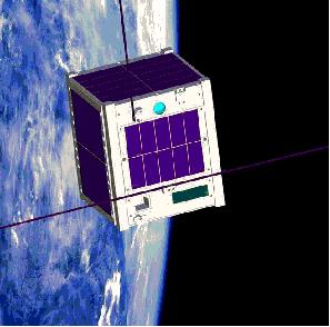
XI-IV (X-factor Investigator)
XI-IV is the name of a picosatellite project of ISSL (Intelligent Space Systems Laboratory) at the University of Tokyo (UT), a participant in the CubeSat program. The objective is to demonstrate and to validate a picosatellite bus system and the space use of commercial-of-the-shelf (COTS) parts. This includes also the successful on-orbit operation of the picosatellite. 1) 2)
The S/C structure conforms to the requirements of the CubeSat program in size and mass. The S/C is 3-axis stabilized, attitude is controlled by passive stabilization of a permanent magnet (a torque is generated to align the Earth's magnetic field and the spacecraft's dipole moment). Power is provided by body-mounted solar cells (single crystal silicon, 60 cells on six surfaces). An average power of 1.2 W is available (average consumption of 620 mW). A manganese type lithium-ion battery provides power (780 mAh) during orbital eclipses. 3) 4)
A total of three spacecraft models were manufactured prior to the flight model, referred to as “XI-IV,” i.e. the fourth model in the XI series. Another flight model, XI-V, is a fully equipped spare on the ground. It is being used in the laboratory in support of simulations whenever a certain operational aspect or procedure has to be tested.
Parameter | Value | Parameter | Value |
Size of satellite | 10 cm x 10 cm x 10 cm | OBC | PIC16LF877, 8bit, 4MHz |
Uplink | 145 MHz FM, 1200 bit/s | Downlink (FM) | 437 MHz FM, 1200 bit/s |
Solar cells | Monolithic silicon (16%) | Antenna | 437 MHz CW, 80 mW |
CW beacon | 800 mW | S/C structure | Aluminum A7075 |
Thermal control | Passive | Attitude control | Passive with permanent magnet (1300mT), hysteresis damper |
RF communication system: Onboard data storage of up to 64 kbyte. A standard Tx-TNC (Terminal Node Controller) PIC16C622 is used with 128 byte of cache memory. The downlink frequency is 437.490 MHz (UHF), FSK modulation, AX.25 protocol, data rate of 1.2 kbit/s, RF output power of 1 W. The uplink employs a Rx-TNC, PIC16C711, the frequency is in VHF, FSK modulation, AX.25 protocol, data rate of 1,2 kbit/s. In addition there is a beacon at 436.8475 MHz, CW (Continuous Wave), 100mW. Antenna deployment takes place after S/C deployment and OBC activation. The S/C is being operated by the UT amateur (Ham) radio station (6-7 passes per day). In addition, any worldwide amateur radio station is capable of telemetry data reception. 5)
Sensor Complement
CMOS camera: The XI-IV payload consists of a CMOS color camera for experimenting in imaging technology. The detector has a physical size of about 0.8 cm x 0.8 cm and contains 644 x 484 pixels in the visible spectrum. The lens has a focal length of 6 mm, f/1.8. The camera is operated in a snapshot fashion. The FOV is about 35º x 35º, each image covers a ground area of 510 km x 530 km from orbital altitude with a spatial resolution of about 4 km. The source data is available as 8 bit RGB output. Some onboard preprocessing is performed for data volume reduction (15,360 pixels). An image in the downlink contains 128 x 120 pixels due to the very limited data rate capacity. The camera has a mass of 20 gram with a power consumption of 120 mW. 6)
Since the satellite attitude cannot be controlled actively, it is difficult to say what image will be taken prior to a snapshot. However, it is possible to command the camera to observe in a preset time interval. Due to the low-rate downlink it takes 2 to 3 days to get even one image fully downlinked.
Mission Status
- 26 December 2020: The picosatellite and its instruments were confirmed to be operational.
- October 2005: The picosatellite and its instruments are operational. There are two main problems (non fatal) on orbit: a) there is an A/D conversion anomaly due to the higher output voltage of solar cells than expected, and b) there is a recurrent OBC reset attributable to a software error.
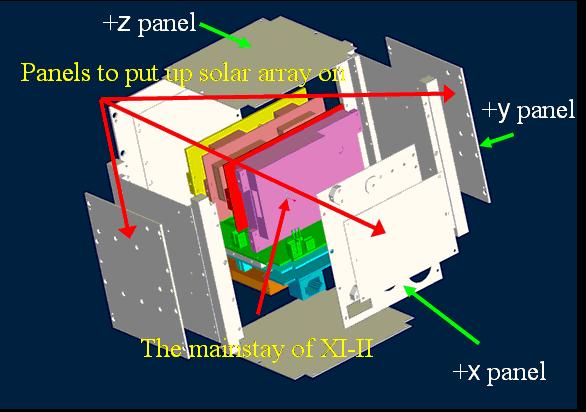
CUTE-I (Cubical Tokyo Tech Engineering Satellite-I)
CUTE-I is a cooperative project within the CubeSat program between LSS (Laboratory for Space Systems) of the Tokyo Institute of Technology (TITech) and SRTL (Space Robotics and Teleoperations Laboratory) of Tokyo. The objectives call for a student designed and developed picosatellite using a low-cost approach with COTS components. In fact, student involvement is required in all project phases. The project definition considers the following mission functions: 7) 8) 9)
1) Communication mission, involving:
- Continuous transmission of CW-Telemetry by a CW-transmitter (operated as a beacon)
- Transmission of FM-Telemetry including payload (housekeeping) data by two different protocols [AX.25 protocol, and SRLL(Simple Radio Link Layer) protocol]. Note: SRLL employs 32 byte fixed-length data packets and provides the function of error correction. Comparison of the two protocols.
- Change of the two communication protocols by uplink command from ground station
2) Sensing mission: Monitoring and control of all onboard sensors like: thermometers, accelerometers, gyros, sun sensor, in short: housekeeping data.
3) Deployment mission: Monitoring and control of the solar panel deployment.
The S/C structure conforms to the requirements of the CubeSat program in size and mass. The satellite is 3-axis stabilized. Power is provided by surface-mounted solar cells (silicon, power of 1.5 W, bus voltage of 5 V, 3.8 V for transmitter) and by a deployable solar panel. Lithium-ion batteries are used for eclipse operations (1.4 Ah). The OBC employs a Hitachi CPU (H8/3334Y) with a 4 Mbit SRAM memory.
The RF communication is based on amateur radio standards. The downlink frequency is in UHF (430 MHz band). The uplink is in VHF (144 MHz). The AX.25 or SRLL protocols are used, modulation = Bell 202, data rate = 1.2 kbit/s. CW telemetry is used to be able to find the satellite on each pass. The telemetry data are stored in an onboard memory or are output to a TNC (Terminal Node Controller) to transmit them to the ground stations. The satellite is being operated by the TI-Tech ground station. In addition, anyone with an amateur radio station is able to receive CUTE-I telemetry.
Communication subsystem | Tx1 | CW transmitter output, 100 mW |
Tx2 | FM transmitter output 350 mW | |
Rx | FM receiver | |
Antenna | Monopole x 3 | |
TNC | Ax.25 1200 bit/s (FSK) | |
Ax.25 1200 bit/s (FSK) | ||
MPU: H8/300 | ||
CW Keyer | MPU: PIC | |
Attitude sensors | Gyro (4) | 4 axis |
Accelerometer | 4 axis | |
Sun sensor (CMOS type) | Original | |
Thermistor | 15 points | |
C&DH (Command and Data Handling) | MPU | H8/300 |
Memory | 4Mbit SRAM | |
Power subsystem (generates voltage at 5.0 V, 3.7 V, and 3.3 V) | Battery | Lithium-ion |
Solar cells | Silicon |
Mission Status
• Successful launch
• Antennas and solar cell paddle were deployed successfully
• Transmission of CW beacon, onboard-Rx works well
• Transmission of FM packet (AX.25, 1200 bit/s) was conducted successfully by uplinked command
• Transmission of FM packet (SRLL, 1200 bit/s) was conducted successfully by uplinked command
• Downlink SRAM data (immediately after separation) was conducted successfully
• Sensor tests: All onboard sensors work well
CUTE-I was in a stable spin gradually until early November 2003, because the rotation speed of CUTE-I was slow. CUTE-I was beginning to be unstable since the middle of November. One of the reasons is the internal energy dissipation effects, e.g. an elastic structural deflection of antennas, solar cell paddle and internal harness of CUTE-I on board electronics. CUTE-1 is operational as of July 2004.
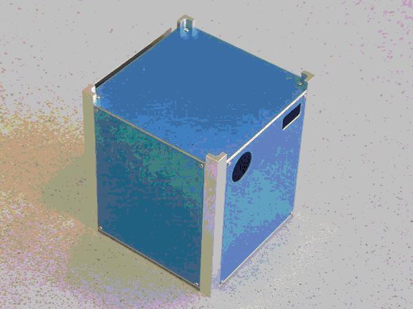
AAUSat (Aalborg University CubeSat)
AAU-CubeSat (or AAUSat) is a student-developed picosatellite within the framework of the Stanford CubeSat program of Aalborg University, Aalborg, Denmark. The spacecraft project started in the summer of 2001, it is a joint venture of several cooperating institutes at the university, namely: Institute of Electronic Systems, Institute of Mechanics, Institute of Computer Science, Institute of Energy Technology, and the Institute of Electrical Engineering. 10) 11)
The S/C structure conforms to the requirements of the CubeSat program in size and mass consisting of five subsystems:
• ADCS (Attitude Determination and Control Subsystem)
• PSU (Power Supply Unit) consisting of the solar panels, electronics and batteries
• OBC (OnBord Computer)
• COM (Communication Subsystem)
• CAM (Imaging Camera) - the payload
The S/C is 3-axis stabilized, attitude is measured by a magnetometer and by sun sensors, three electromagnetic coils serve as actuators. The pointing accuracy is within 5-10º. The S/C may be body-pointed into various directions (by the coils over a period of 2-3 orbits). S/C power is provided by surface-mounted triple-junction solar cells (1.4 W average). Four lithium-iodine batteries (nominal voltage of 3.7 V, capacity of 920 mAh) provide power for eclipse operations. The OBC (16-bit CPU of Siemens) consists of the following elements: MCU (Micro Controller Unit, 16 MByte), RAM (2MByte payload data), Flash ROM (updated applications), I2C (Interconnected Integrated Circuit) bus interface of Philips, and external logic to control the system (all communication between OBC and subsystems is via I2C). The main support functions of OBC are: data handling subsystem, control of ACS (Attitude Control Subsystem), interface to other subsystems [PSU (Power Supply Unit) Communication Unit], bus arbitration, etc.
RF communication is provided by an amateur radio link. in UHF-band (430-450 MHz), the downlink data rate is 9.6 kbit/s, the AX.25 protocol is used. The S/C will be operated by students of Aalborg University. The images recorded on-board will be transmitted to the ground station at Aalborg University, from where they will be distributed over the Internet (access to general public).
Sensor Complement
CAM (Imaging Camera) is based on Kodak MCM20027 camera chip [KAC-1310, 1280 x 1024 pixel SXGA, a solid-state ACI (Active CMOS Imager), a camera on chip]. The camera is sponsored by Devitech (Digital Vision Technology), Nørresundby, Denmark (cooperative agreement with AAU). The objective is to take imagery (scenes of about 150 km x 115 km in medium resolution) of the Earth's surface, in particular of Denmark. Danish companies and research institutes are invited to formulate their scene requests via internet. Each image has a volume of 2.6 MByte, on-board storage is provided for one image. - A secondary objective is to measure starlight intensities. The KAC-1310 system is a fully integrated, high performance 2-D optical format Megapixel CMOS image sensor (size of photosensitive area is 7.68 mm x 6.14mm), including integrated timing control and programmable analog signal processing. The source data is provided with a color depth of 24 bit. The spatial resolution is about 100 m x 100 m at an orbital altitude of 820 km. The camera lens is designed and developed at AAU; it has an aperture diameter of 2 cm and a total length of 5 cm (FOV of 10º).
Mission Status
Following launch (June 30, 2003), the satellite was alive for two and a half months before the battery had lost too much capacity to continue operations. During this time only a limited amount of data was successfully downlinked from the satellite due to an undisclosed problem on the satellite transmitter resulting in very weak signals being transmitted. - Still, as a first step into picosatellite technology and student built satellites, the projects is considered a success and will be followed up by a new student satellite (AAUSat-II), under definition in 2004, which will have the benefit of all the experience gained with AAUSat.
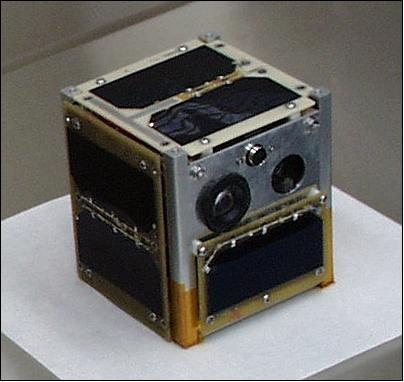
CanX-1 (Canadian Advanced Nanospace eXperiment-1)
CanX-1 is the first picosatellite of UTIAS/SFL (University of Toronto, Institute for Aerospacestudies/Space Flight Laboratory) within the CubeSat frame of reference. The overall program objectives are to promote the development and testing of low-cost space technologies and to verify the functionality of several novel electronic technologies in orbital space. The CanX-1 mission is intended to demonstrate a highly capable spacecraft with its payloads and experimental subsystems. They are: 12) 13) 14)
• Testing of CMOS imagers for observation of the Earth, the moon, and tracking of stars
• A powerful OBC (Onboard Computer) based on an Atmel's ARM-7 microprocessor
• A GPS receiver
• An active magnetic control system including B-dot detumbling and 3-axis stabilization
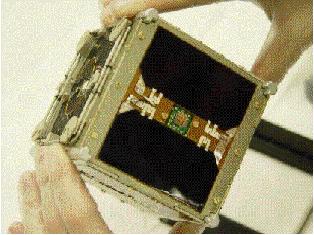
The CanX-1 spacecraft conforms to the CubeSat standards with outer dimensions of 10 cm side length. The S/C must have four launch rails along four edges of the cube, allowing for easy ejection from the P-POD launch tube. To maintain spacing and prevent sticking with other CubeSats, standoff contacts or feet must exist at the ends of these rails. The center of mass of CanX-1 must be within 2 cm of the geometric center. The maximum mass of CanX-1 is 1 kg, and it is desired that the structure be no more than approximately 30% of the total satellite mass.
The interior structure of CanX-1 consists of four circuit boards, parallel to the x-y plane, for instrument/subsystem mounting. The power subsystem consists of a battery pack, solar arrays, a peak power tracker, a shunt regulator, and a power distribution module. Lithium-ion batteries are used with the cells connected in parallel, resulting in a 3.6 Ah nominal capacity at 3.7 V. Six surface-mounted solar arrays with triple-junction GaAs cells provide an average power of 1.63 W per array at 4.4-5 V output. Power is permanently supplied to the OBC and RF transmitter/receiver (radio), while power to the rest of the subsystems and payloads are switchable and are controlled by the OBC. - The ACS (Attitude Control Subsystem) employs magnetic control consisting of of three orthogonal torquer coils (actuators), and a three-axis magnetometer (sensor to measure the magnetic field). For detumbling purposes, a B-dot control algorithm is being implemented as part of the OBC software. A worst case control torque of 2.33 x 10⁻⁶ Nm is available. - The S/C is flying a custom-designed housekeeping computer based on the low-power ARM-7 core, operating at up to 40 MHz. The OBC uses three types of onboard memory: a small boot ROM (128 kByte), a large Flash-type memory (32 MByte), and a moderate amount of SRAM (2 MByte). The boot ROM contains a small amount of boot-strap code, capable of very basic spacecraft operations - initialization code, keep-alive functionality, and communication code. In addition, a number of utility functions such as memory error detection and correction (EDAC) routines are present on the boot ROM. - The RF communications subsystem consists of a radio receiver, a radio transmitter, antennas, antenna switching hardware, and a TNC (Terminal Node Controller). The VHF downlink (900 MHz carrier, IF = 166.287 MHz) employs BPSK modulation with forward error correction, the uplink is based on a 900 MHz FM design (carrier of 910.7 MHz, IF = 49.3 MHz, 10.7 MHz). Data rates of 1200, 2400, or 4800 baud are supported.
Sensor Complement
CMOS imagers. The S/C carries two independent units providing high-resolution imagery. The objective is to:
• Validate the use of spaceborne CMOS imagers for science and engineering
• Provide star-field imagery for the purpose of attitude determination via star- and moon-tracking, as well as Earth-horizon tracking
• Provide educational imagery of the moon and the Earth.
The imagers are COTS CMOS imaging chips manufactured by Agilent Technologies. Each imager has its own lens system. The color imager utilizes a wide field-of-view (FOV) lens. This makes it suitable for imaging the Earth and the moon. The monochrome imager uses a narrow FOV lens system. The plans call for onboard image compression using a standard compression algorithm (ZIP).
Parameter | Color | Monochrome |
Model | HDCS-20220 | ADCS-2020 |
Quantum efficiency | 33% | 38% |
Fill factor | 42% | 42% |
Lens focal length | 2.1 mm | 25 mm |
Lens aperture | f/2 | f/2.5 |
Diagonal FOV | 112º | 14º |
Nadir resolution | 1.5 km/pixel (based on 650 km orbit altitude) | 200 m/pixel |
Power consumption | 200 mW | 200 mW |
GPS receiver (Superstar GPS OEM board, from CMC Electronics). A compact commercial GPS receiver along with associated antennas is being used for or coarse determination of orbit parameters. The instrument requires power of 1.2 W (max), has a size of 46 mm x 71 mm x 13 mm, a mass of 22 gram, and a sensitivity of -135 dBm.
Mission Status
CanX-1 was launched on June 30, 2003 (along with the other CubeSats). Unfortunately, the CanX-1 team was not able to get a spacecraft communication going. During successive initial passes, the ground team sent ping frames to the satellite and commanded a system reset with fire-codes. In order to verify the performance of the CanX-1 ground station, the team was able to track and acquire the beacons of other satellites launched on this mission.
The inability of any spacecraft operations was indeed a painful experience to all concerned. Despite the post-launch problems, the design, construction and testing processes have provided invaluable experience to ten graduate students at the University of Toronto. A new team of students is currently conducting preliminary design work on a next-generation satellite called CanX-2 and there are plans for a future series of satellites.
DTUSat (Technical University of Denmark Satellite)
DTUSat is a student-defined and student-developed project at DTU, started in 2001. The spacecraft conforms to CubeSat specifications. The mechanical structure is built on a monolithic wire-frame cube, milled out of a solid piece of aluminum. It contains a likewise monolithic semi-cube, interconnecting all 4 main PCBs (Printed Circuit Board) both electrically and mechanically.
The payload requirements call for a three-axis stabilized spacecraft. Attitude control is provided by three-axis magnetorquers. This configuration has a total mass of 40 gram, it is capable of producing a torque of 0.6-1.5 µNm (depending on the magnitude of the geomagnetic field). The control principle selected is B-dot control. In B-dot control, the gradient of the measured magnetic field of the Earth is used as rate feedback to obtain a stabilized satellite, and an additional constant magnetic dipole moment is generated to align the satellite with the magnetic field (very similar to a permanent magnet). Attitude information is provided by 5 sun sensors and a four-axis magnetometer providing a measurement range of 60 µT and an accuracy of <±50 nT. The sun angle sensing is provided by the 5 solar panels one on each face of the satellite except the payload face. 15) 16)
The sun angle sensing package is a DTU development; it employs MOEMS (Micro Optoelectronic-Mechanical System) technology consisting of a SOI (Silicon-On-Insulator) based two-axis linear slit sensor chip with a FOV of ±70º and a theoretical resolution of about 0.07º. Each sun sensor is a composition of a Pyrex glass wafer on top of a SOI wafer. A SOI wafer is used since it enables electrical insulation by etching away the top mono-crystalline Si-layer. The mass of the entire sun sensor package is just below 3 gram. The power provided by the solar cells is about 1.75 W (triple-junction solar cells from Emcore are being used). A single commercial Lithium-ion battery provides power during eclipse phases. 17)
The OBC is based on an Atmel AT91M40800 32 bit RISC processor running at 16 MHz with 2 MB Flash, 1 MB RAM, and 16 kB ROM for radiation and fault resistant boot software. DTUSat uses a pure star configuration for simplicity. All modules are directly connected to the computer and perform no autonomous functions except comparator-type safeguards.
RF communications employs AMSAT concepts. The uplink and downlink frequencies for all communication are 437.475 MHz. Data are modulated using 2400 bit/s AFSK. The AX.25 packet format and protocol is used for digital radio communication.
Sensor Complement
DTUSat carries three payloads, namely an electrodynamic tether, a camera, and a radio test broadcaster.
ETE (Electromagnetic Tether Experiment) is the primary payload on DTUSat. The tether employs a bare (un-isolated) copper wire of about 450 m length (.02 mm in diameter), picking up free electrons in the plasma trapped in the Earth's magnetic field. By emitting electrons from the satellite body, the tether (and satellite) will be positively charged. It will attract electrons, and a current will flow in the string. As the satellite, and thus the tether, moves in the magnetic field of the earth, this gives a resulting force on the satellite, as the return current will flow in the plasma. The mechanical system, consisting of tether and satellite, will therefore see a force in only one direction, making it possible to change the spacecraft orbit without using fuel. - The tether is deployed from a yo-yo-like spool, which is ejected by a spring, receiving both linear and angular velocity balanced to keep the satellite attitude stable and the tether tension low. The spool is braked at the end of travel by using a sticky glue to fasten the inner layers, again minimizing tension in the wire without generating space debris. The tether is electrically connected to the satellite structure. A possible future application of the tether experiment is object removal from space.
Camera: The objective is to provide some means of Earth imaging. The instrument employs a CCD detector of size 640 x 480 pixels and is operated in snapshot fashion. At the nominal altitude of 650 km, a snapshot covers a target area of 482 km x 336 km providing a spatial resolution of 750 m. - Unfortunately, the camera did not get ready in time for launch. The satellite is flying a dummy mass instead to compensate the camera mass.
Radio test receiver/broadcaster: The objective is to provide a dual-use communication capability (support of spacecraft and AMSAT services). The radio test broadcaster sends out a sequence of messages that decreases in signal amplitude. This will help radio amateurs to test their equipment. In return for this service, AMSAT provides the DTUSat team with a radio frequency.
Mission Status
After launch on June 30, 2003, the DTUSat team was not able to establish any communications with the spacecraft. Even though the satellite did not fulfill its mission, the main goals of the project are still achieved: education of 70+ students, a lot of outreach activities and a satellite, which was declared flightworthy.
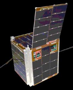
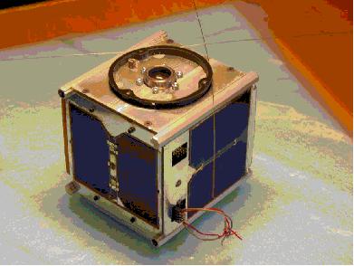
QuakeSat
QuakeSat is a research nanosatellite of the QuakeFinder Team of Palo Alto, CA, and SSDL (Space Systems Development Laboratory) at Stanford University, Stanford, CA, with the objective of earthquake signature detection. QuakeSat's primary scientific mission is to detect, record, and downlink ELF (Extremely Low Frequency) magnetic signal data, which may lead to groundbreaking techniques to predict earthquake activity. According to theory, fracturing bedrock along the fault lines creates the ELF magnetic waves. These signatures radiate from the earthquake hypocenter region (several tens of km2), through the Earth (5-80 km), through the atmosphere to the ionosphere (100-200 km), and are propagated up the Earth's magnetic field lines to satellite altitude. 18) 19) 20) 21) 22)
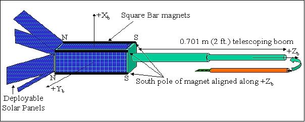
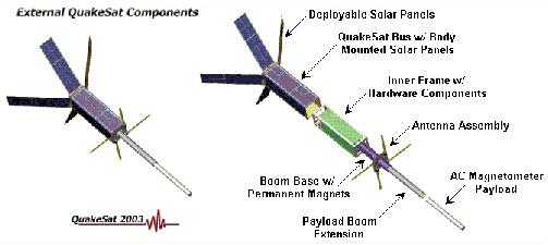
The nanosatellite design is based on the CubeSat concept where each CubeSat is of 10 cm side length. QuakeSat is in fact a triple CubeSat to provide a large enough size to include a 30 cm long magnetometer that extends on a telescoping boom. QuakeSat is a prime example of CubeSat technology, which utilizes COTS (Commercially-Off-The-Shelf) components for scientific experiments and payloads. QuakeSat measures slightly more than 10 cm x 10 cm x 30 cm (stacking of three CubeSat payloads) with a total mass of about 4.5 kg. The outer structure of QuakeSat (consisting of 6061 aluminum) fits inside the P-Pod launch tube. The S/C subsystems are:
- ADCS (Attitude Determination and Control Subsystem). Permanent magnets are used for attitude control to keep the magnetometer aligned close to the Earth's magnetic field. Four magnets are being used, each of size 6.35 mm x 6.35 mm x 102 mm and a mass of 0.224 kg. By aligning the magnets along the boom axis constraints QuakeSat to fly nearly parallel to the magnetic field lines as the S/C rotates twice per orbit about an axis perpendicular to the boom (+Zb) axis. The QuakeSat boom is nadir pointing over the North Pole and zenith pointing over the South Pole. Two hysteresis rods are used for damping. Solar array current measurements are beiing used to determine the attitude with respect to the sun. From this input an attitude estimation is being done to determine how close the magnetometer sensor is aligned to the Earth's magnetic field and how much of an ELF signal is measured.
- The EPS (Electric Power System) consists of a power source, power storage and a power regulator. The power source consists of 12 solar arrays: four body-mounted panels and four are double-sided deployable wings. Two Li-ion batteries are being used.
- C&DH (Command and Data Handling). C&DH consists of a Prometheus CPU module (Diamond Systems) with Ethernet and data acquisition all on a single board (64 MByte memory and 128 MByte of flash disk). A Linux operating system is being used. A major function of C&DH is to monitor all S/C functions (there are 48 housekeeping sensors, etc.). Onboard storage for one day of science data is provided.
- RF communications. The UHF band (436.675 MHz, 20 kHz bandwidth) is being used for uplink and downlink communications. The AX.25 protocol, standard in the ham radio community, is being used for the communication protocol. The two major components of the Communications subsystem are the BayPac BP-96A modem and the Tekk T-Net mini 960 radio.
Orbit | SSO (Sun-Synchronous Orbit) dawn-dusk, mean altitude about 840 km |
Spacecraft dimensions | 150 cm x 80 cm x 80 cm (deployed); 35 cm x 11 cm x 11 cm (stowed) |
Spacecraft mass | 4.5 kg |
Power (solar arrays) | 12 solar panels (4 body fixed and 4 double sided deployable) |
Power (batteries) | 2 Li-ion batteries (3.0Ahr total) (Failed open circuit on Jan. 24 and Jan. 28, 2004, respectively) |
Power load | 3.6 W continuous |
Power load (transmitter) | 1-1.4 W, depending on bus voltage |
Communication | 436.675 MHz half duplex, 9600 baud |
Attitude control | Passive magnetic stabilization, (likely not maintaining pre-launched planned attitude) |
Attitude determination | 12 solar array currents primary, IR and temperature sensors as secondary. (However, Mux with primary channels failed at launch.) |
OBC | Prometheus PC-104, down clocked to 66MHz, 32 RAM |
Data quantization | 16 channel, 16bits up to 3000 samples/sec |
Onboard storage | 128 MB Flash, up to 64 MB available for data collection |
Sensor Complement
Magnetometer. The objective is the detection of ELF signatures. The strategy used to detect the small magnetic field measurements (0.5 to 1000 Hz) relies on the use of a very sensitive AC magnetometer. The ELF sensor is a single axis, search coil (induction) type magnetometer with multiple frequency bands. The magnetometer features:
• Two 25,000 turn coaxial coils + a calibration coil
• Low noise preamp with negative resistance circuit (GSFC)
• Sensitivity: 10 pT noise floor (theoretical)
• Dynamic range: 80-100 db (low and high gain mode) 16 bit A/D conversion
Band (or mode) | Description | Collection limit |
Band 1 (mode 1) | 0.5 - 10 Hz narrow band B field @ 50 samples/s | 100 min continuous |
Band 2 (mode 2) | 10 - 150 Hz wide band B field @ 500 samples/s | 10 min continuous |
Band 3 (mode 3) | 10 - 1000 Hz wide band B field @ 3000 sample/s | 100 sec continuous |
Band 4 (mode 4) | 140 Hz [127-153 Hz pass band (E and B field)] @ 500 samples/s | 30 sec continuous |
The magnetometer is 30.5 cm long and 1.9 cm in diameter, it extents into a telescoping boom. All bands are sampled 2-3 times/s at their highest frequency, band 4 is excepted with a sampling rate of 1/s. The segmented (telescoping) boom has a total length of 701 mm. Total mass (boom + sensor) = 0.822 kg.
The sampling strategy for the magnetometer data maps the world into 5º x 5º grids of latitude and longitude. The 5º resolution was derived to allow the sensor to be turned on and calibrated prior to passing over an area of high earthquake activity. Also by using a 5° grid, the selected earthquake areas results in a 15% duty cycle for the payload, resulting in dramatically reduced power requirements.
The position of QuakeSat on the world map is determined through TLE (Two Line Element) sets provided by NORAD and a ground-based propagator. The TLE data sets are estimated to give an error in position of approximately < 10 km. The determination of QuakeSat's orbital position is being calculated on the ground; a table of payload turn-on and turn-off times that correspond to QuakeSat's movement through each 5º box on the map is being uploaded to allow the C&DH to collect ELF data throughout QuakeSat's orbit.
Mission Status
• QuakeSat was designed to fly for one year, but the mission ended up lasting for 1 ½ years to the end of December 2004. 23)
• The spacecraft and its instruments are operational as of Sept. 2004. A total of nearly 2000 magnetometer collections were made of all modes, primarily in the mode 2 configuration (10 to 150 Hz), roughly 500 MB raw binary uncompressed data. The areas targeted were primarily, 1) likely earthquake regions, hoping to catch a signal before an event and 2) significant post earthquake collections in the region surrounding the earthquake. In addition, over a 100 collections were made looking for lightning strikes and several global 1-10 Hz surveys were made.
• June 15, 2004: The QuakeSat mission is quickly approaching its one year point. Although the satellite has now begun encountering periodic reboots due to brief eclipsing of the sun due to the earth in its sun synchronous orbit, QuakeSat continues to make payload data collection and data downloads.
• Jan. 20, 2004: After nearly 6 months in low earth orbit, QuakeSat lost both of its primary batteries within 4 days of each other. This may have been due to the result of the high battery temperatures that have reached upwards of 120 degrees Fahrenheit. QuakeSat is again in a sun synchronous orbit that is currently in the sun all day, and everyday. At this temperature it is possible that the electrolyte had “baked out” since the batteries were not sealed beyond the normal factory packaging. 24)
Nevertheless, QuakeSat's power subsystem is rather robust, and it is currently operating off of pure solar power. This has resulted in a significant degradation in mission performance, however, we are still collecting and downloading nearly one-third the amount of data that we have been operating at thus far over the past six months.
• December 22, 2003: ELF signal detected near San Simeon, CA, M 6.5 quake (Ref. 21).
References
1) https://web.archive.org/web/20170819124928/http://www.space.t.u-tokyo.ac.jp:80/cubesat/index-e.html
2) Y. Nakamura, T. Eishima, M. Nagai, R. Funase, et al., “University of Tokyo's Ongoing Student-Lead Picosatellite Projects - CubeSat XI and PRISM,” Proceedings of IAC 2004, Vancouver, Canada, Oct. 4-8, 2004, IAC-04-IAA-4.11.4.06
3) R. Funase, Y. Nakamura, M. Nagai, T. Eishima, K. Nakada, A. Enokuchi, C. Yuliang, E. Takei, S. Nakasuka, “University of Tokyo's Student Nanosatellite Project CubeSat-XI and its On-orbit Experiment Results,” 16th IFAC Symposium on Automatic Control in Aerospace, June 14-18, 2004, Saint Petersburg, Russia
4) Y. Tsuda, N. Sako, T. Eishima, T. Ito, et al., “University of Tokyo's CubeSat Project - Its Educational and Technological Significance,” AIAA/USU Conference on Small Satellites, Logan UT, Aug. 13-16, 2001, SSC01-VIIIb-7
5) http://dat15.t.u-tokyo.ac.jp/cubesat/mission/index-e.html
6) Information provided by Nobutada Sako of ISSL, University of Tokyo
7) K. Omagari, K. Konoue, H. Sawada, K. Nakaya, K. Ui, M. Iai, N. Miyashita, T. Urabe, et al., “Tokyo Tech 1 kg Picosatellite CUTE-1 - Development, Launch & Operations,” 16th IFAC Symposium on Automatic Control in Aerospace, June 14-18, 2004, Saint Petersburg, Russia
8) http://horse.mes.titech.ac.jp/srtlssp/cubesat/index.html
9) K. Nakaya, K. Konoue, H. Sawada, et al. “Tokyo Tech CubeSat: CUTE-I - Design & Development of Flight Model and Future Plan,” AIAA 21st International Communications Satellite Systems Conference and Exhibit, Yokohama, Japan 2003, AIAA, pp. 2003-2388
10) Information provided by Elmo Schreder of AAU
11) L. Alminde, M. Bisgaard, D. Vinther, T. Viscor, K. Z. Østergard, “The AAU-CubeSat Student Satellite Project: Architectural Overview and Lessons Learned,” 16th IFAC Symposium on Automatic Control in Aerospace, June 14-18, 2004, Saint Petersburg, Russia
12) G. J. Wells, L. Stras, T. Jeans, “Canada's Smallest Satellite:- The Canadian Advanced Nanospace eXperiment (CanX-1),” AIAA/USU Conference on Small Satellites, Logan, UT, Aug. 12-15, 2002, SSC02-VI-2
13) https://web.archive.org/web/20131209082016/http://utias-sfl.net/nanosatellites/CanX1/CanX1Index.html
14) Luke Stras, Daniel D. Kekez, G. James Wells, Tiger Jeans, Robert E. Zee, Freddy Pranajaya, Daniel Foisy, “The Design and Operation of The Canadian Advanced Nanospace eXperiment (CanX-1),” Proceedings of AMSAT-NA, 21st Space Symposium, Toronto, Canada, Oct. 2003, pp. 150-160, URL: https://web.archive.org/web/20100827082425/http://www.utias-sfl.net:80/docs/canx1-amsat-2003.pdf
15) J. H. Hales, M. Perdersen, “Two-Axis MOEMS Sun Sensor for Pico Satellites,” AIAA/USU Conference on Small Satellites, Logan, UT, Aug. 12-15, 2002, SSC02-VI-6
16) K. Krogsgaard, “Compact Vector Magnetometer for Pico Satellites,” Proceedings of the AIAA/USU Conference of Small Satellites, Logan ,UT, USA, Aug. 11-14, 2003
18) http://www.quakefinder.com/services/quakesat-ssite/
19) Matthew Long, Allen Lorenz, Greg Rodgers, Eric Tapio, Glenn Tran, Keoki Jackson and Robert Twiggs, Thomas Bleier, “A CubeSat Derived Design for a Unique Academic Research Mission in Earthquake Signature Detection,” AIAA/USU Conference on Small Satellites, Logan, UT, Aug. 12-15, 2002, SSC02-IX-6, URL: http://www.quakefinder.com/research/pdf/SSC_PAPER_SSC02-IX-6.pdf
20) S. Flagg, T. Bleier, C. Dunson, J. Doering, L. DeMartini, P. Clarke, L. Franklin, J. Seelbach, J. Flagg, M. Klenk, V. Safradin, “Using Nanosats as a Proof of Concept for Space Science Missions: QuakeSat as an Operational Example,” 18 Annual AIAA/USU Conference on Small Satellites, Logan, Utah, Aug. 9-12, 2004, SSC04-IX-4,
21) Tom Bleier, James Cutler, Eric Tapio, Allen Lorenz, Bob Twiggs, “QuakeSat: Low Cost University/Commercial Nanosatellite Collaboration,” CubeSat Developers Workshop, CalPoly, San Luis Obispo, CA, USA, April 8-10, 2004, URL: http://mstl.atl.calpoly.edu/~workshop/archive/2004/Spring/04b-Bleier-QuakeSat.pdf
22) Tom Bleier, Paul Clarke, James Cutler, Louis DeMartini, Clark Dunson, Scott Flagg, Allen Lorenz, Eric Tapio, “QuakeSat Lessons Learned: Notes from the Development of a Triple CubeSat,” URL: http://insa.netquire.com/docs/Lessons_Learned_Fina.pdf
23) Tom Bleier, Clark Dunson, “Simultaneous ELF Magnetic Field Monitoring of Earthquakes from a Nano-Satellite (QuakeSat) and a Ground Network,” 4th IWSE (International Workshop on Seismo Electromagnetics), Tokyo, Japan, March 15-17, 2005, URL: http://www.quakefinder.com/research/pdf/L3-3%20Bleier.pdf
24) http://www.quakefinder.com/services/quakesat-ssite/qs_january_20_full_report.htm
The information compiled and edited in this article was provided by Herbert J. Kramer from his documentation of: ”Observation of the Earth and Its Environment: Survey of Missions and Sensors” (Springer Verlag) as well as many other sources after the publication of the 4th edition in 2002. - Comments and corrections to this article are always welcome for further updates (eoportal@symbios.space).