CubeSat Concept
Initiatives and Programs
Related resources
CubeSat Concept and the Provision of Deployer Services
The CubeSat program is a first attempt towards a picosatellite standard development. CubeSat is the name given to a cube-shaped picosatellite design of 10 cm side length (a cube of 10 cm x 10 cm x 10 cm with a total mass budget limit of 1 kg).
The CubeSat concept and program started in 1999 at SSDL (Space Systems Development Laboratory) of Stanford University under the leadership of Robert J. Twiggs. [Note: The CubeSat concept was initially presented and proposed by R. J. Twiggs at the USSS (University Space Systems Symposium), Kauai Beach Hotel, Kauai, Hawaii, Nov. 6-8, 1999].
The idea was to meet an educational need to define a meaningful satellite mission that could be developed within a timeframe of a year or two, be of very-low cost, and be of very low mass for reduced launch costs. - It turns out that picosatellites offer very promising scenarios to demonstrate new small-scale space technologies and mission concepts (testbed capability for low-power and low-mass devices such as MEMS). CubeSats, combined with new sensor, communications, and networking capabilities, may be able to carry out formation flight demonstrations in support of multi-point observations. - In the meantime, Stanford University and California Polytechnic State University in San Luis Obispo, CA (referred to as CalPoly) have combined efforts to develop a means of launching small standard picosatellites called CubeSats. 1) 2) 3) 4)
The overall objective of the CubeSat program is to provide an effective framework (including specifications and guidelines) for the design, construction and launch of picosatellites. Defining a standard bus, developing standard hardware components using commercial off-the-shelf (COTS) components and a standard spacecraft frame will simplify the development of picosatellites. The CubeSat development will provide a standard spacecraft frame, a spacecraft controller, radio transceiver, attitude determination and control, solar cells, batteries, and an interface for a payload. The intend is to free the developer from repetitive spacecraft designs; thus, he should be able to concentrate on the payload. Nonetheless, a big challenge remains in the integration and packaging of all the subsystems into a very limited volume of available space.
Note: At the start of the 21st century, the picosatellite subsystem of “power” is still rather underdeveloped. Thus, tiny power budgets in the order of 100 mW of continuous power from solar cells limit the operational capabilities of any picosatellite mission.
P-POD (Poly-Picosatellite Orbital Deployer)ta
The CubeSat launch concept selected permits the launch of multiple secondary payloads which may be stacked into a launcher tube, called P-POD (Poly-Picosatellite Orbital Deployer), developed by CalPoly. P-POD is a standard deployment system that ensures all CubeSat developers conform to common physical requirements. The P-POD plays a critical role as the interface between the launch vehicle and CubeSats. It utilizes a tubular design and can hold up to 34 cm x 10 cm x 10 cm of deployable hardware space.
The P-POD minimizes potential interactions with the primary payload(s) on a launch vehicle by physically enclosing the CubeSats and requiring that they be launched in a dormant “off” state.
The standard P-POD holds up to three CubeSats, it is designed to be attached to many different launch vehicles. The double P-POD holds up to six CubeSats, it uses a common wall to save weight. In a nominal mission sequence, the CubeSats are ejected from the piggy-back P-PODs after reaching orbital altitude. Once safely away each CubeSat will activate itself and begin its mission. 5) 6) 7)
The Key features of the Common Standard are
• The common form factor is, 10 cm x 10 cm x 10 cm, and maximum mass of 1 kg. The common form factor and weight of the CubeSats is necessary to ensure that they are properly integrated into the CubeSat deployer.
• Spring plungers between the CubeSats. They provide the initial separation between the CubeSats after deployment.
• Deployment switches. These ensure that all CubeSats are inactive during launch and pre-launch activities.
Multiple Cubesats can be joined together to form a satellite with increased volume and mass constraints.
CubeSat Designation | Size (max) | Mass (max) |
Cube (1U) | 10 cm x 10 cm x 10 cm | 1 kg |
Double Cube (2U) | 10 cm x 10 cm x 20 cm | 2 kg |
Triple Cube (3U) | 10 cm x 10 cm x 30 cm | 3 kg |
6 Pack (6U) | 10 cm x 20 cm x 30 cm | 6 kg |
Simplicity and reliability are the cornerstones of the CubeSat standard. The standard provides universities with structural, dimensional, and operational guidelines.
Launch opportunities are planned for at least once per year. With the demonstration of low cost picosatellites, and the development of Stanford University's CubeSat program, a new testbed for technology and science demonstrations is gaining acceptance. CubeSat spacecraft, having a mass of about 1 kg, are appropriately suited for test and qualification of microelectronics and MEMS technologies.
CubeSat launch services (arrangements with a launch vehicle provider, coordination, payload integration and test, etc.) are provided commercially by OSSS (One Stop Satellite Solutions) of Ogden, UT for the participants of the CubeSat program. OSSS also provides MPA (Multiple Payload Adapter) for multiple P-POD installation and deployment services. Note: MPA deploys P-PODs while P-POD deploys CubeSats.
Item | Description |
Mass | - Each satellite may not exceed 1 kg of mass |
Structure | - All edges contacting rails must be rounded. Cubesats must have at least 75% (85.125 mm of a possible 113.5 mm) of flat rail contact with the deployer |
Material | - The use of Aluminum 7075 or 6061-T6 is suggested for the main structure. If other materials are used, the thermal expansion coefficient must be similar to that of Aluminum 7075-T3 (the POD material) and approved by CalPoly/Stanford personnel. |
Deployables | - A time delay, on the order of several minutes, must be present between release from the P-POD and any satellite hardware deployment, to allow for satellite separation. |
Communication | - There must be a time delay, on the order of several minutes to an hour, before all primary transmitters are activated. Low power beacon transmitters may be activated after deployment. |
Power | - CubeSats with rechargeable batteries must have the capability to receive a transmitter shutdown command, compliant with FCC regulations. |
General | - Absolutely no pyrotechnics are allowed inside the CubeSat |
Background
During the 1990s, satellite and payload development projects have become the program of choice for challenging (multi-year) training courses in quite a few engineering departments at universities throughout the world. The intent is always to enrich the student training program, to stimulate interest in a problem-solving multi-disciplinary technical environment, to be imaginative and resourceful, and to take some risks – with ample and essential help from mentors and partners (industry, institutional, or otherwise).
Cooperation on many levels and active participation/publication within the international space science community are important ingredients in the overall objectives of research and development. In some instances, project-sharing among engineering departments of several universities is being practiced in order to handle the demanding and complex project goals in a certain time frame. In general, a good amount of enthusiasm and lots of volunteer work by all parties involved are needed to bring such low-cost program activities to maturity - an invaluable amount of professionalism is gained for all students in such programs. 8) 9) 10) 11) 12)
The CubeSat program itself has been created to provide in particular colleges and universities the opportunity to develop and launch small satellites at very low cost -making their launch and operation affordable. Starting in about 2004, the CubeSat initiative has in fact become a global collaborative effort. It represents an ideal platform to demonstrate new technologies and concepts. In this context, experimental failure is a basic element of university life, and from the university's perspective, a failed spacecraft is not necessarily a failed mission.
The CubeSat Standard as a Secondary Payload Enabler 13)
Even though most CubeSat launches to date have followed the traditional secondary launch model, the CubeSat standard has already developed some of the infrastructure required to implement a flexible secondary launch model:
• A well-defined standard is available to both developers and launch vehicle providers. This includes a qualified standard launch vehicle interface (the P-POD) that has already been integrated on a number of launch vehicles.
• A large CubeSat developer community has emerged with worldwide participation from industry, government agencies and academic institutions.
• The launch manifesting process has experienced a substantial centralization with a few organizations supporting integration and contracting efforts for the larger developer community. These organizations include Cal Poly in the U.S., ISIS (Innovative Solutions In Space), Delft, The Netherlands, and the University of Toronto in Canada.
Other Deployer Designs for Pico and Nanosatellites
Next to the P-POD design of CalPoly, there exist other POD designs. The University of Tokyo (Japan) developed T-POD (Tokyo Picosatellite Orbital Deployer) in collaboration with UTIAS/SFL (University of Toronto, Institute for Aerospace Studies / Space Flight Laboratory) of Toronto, Canada. 14)
Note: The other POD developments are not regarded as a competition to P-POD (Poly-Picosatellite Orbital Deployer) of CalPoly; rather, they are considered a complementary element in case of need being offered by a potential launch opportunity.
T-POD (Tokyo Picosatellite Orbital Deployer)
• The first T-POD was flown in 2003 (Rockot launch vehicle on June 30, 2003 from Plesetsk, Russia), using the original design of Tokyo University. The T-POD was used to eject the XI-V CubeSat of the University of Tokyo from the Rockot launch vehicle in a multiple CubeSat launch (6 picosatellites).
• The SSETI Express mission of ESA, launched October 27, 2005, deployed three CubeSat passengers (i.e., picosatellites): UWE-1 (Universität Würzburg Experimentalsatellit-1), Würzburg, Germany; XI-V (X-factor Investigator-V) of the University of Tokyo, Tokyo, Japan; and NCube-2 (Norwegian CubeSat-2) from Norway. The deployment of the CubeSats used the T-POD system; however, this time around it was provided by UTIAS/SFL, based on the T-POD design of the University of Tokyo.
PHS (PRISM Hosyutsu Souchi) is an improved variation of T-POD, built by ISSL (Intelligent Space Systems Laboratory) of the University of Tokyo. The PRISM (Picosatellite for Remote?sensing and Innovative Space Missions) nanosatellite of ISSL (launch 2009, with a launch mass of 8.5 kg and a size of 19.2 cm x 19.2 cm x 40 cm) will use the PHS deployer to protect in particular the boom structure of the PRISM nanosatellite.
Note: In PHS, the term Housyutu means 'ejection' and Souchi means 'system' in Japanese.
CSS (CUTE Separation System)
The Tokyo Institute of Technology (TITech), Tokyo, Japan designed and developed its own deployment system, referred to as CSS (CUTE Separation System), and launched its CubeSats or nanosatellites with this system.
• CSS was flown for the first time to deploy the CUTE-1 (Cubical Tokyo Tech Engineering Satellite) CubeSat. The launch was on June 30, 2003 on a Rockot launch vehicle of ELS (Eurockot Launch Services) from Plesetsk, Russia; the flight involved a multiple payloads, among them also six CubeSats.
• TITech conducted a separate test flight of the modified CSS to demonstrate its behavior. This mission is referred to as: TSD (TITech Separation system Demonstration) which took place on July 10, 2005 as a secondary payload to the Astro-E2 (Suzaku) spacecraft of JAXA/ISAS (Japan Aerospace Exploration Agency/Institute of Space and Astronautical Science), Tokyo.
• An improved version of CSS was used to deploy CUTE-1.7+APD (Cubical Tokyo Tech Engineering Satellite-1.7+ Avalanche Photodiode), a double-cube of TITech. The launch took place on Feb. 21, 2006, on the M-5 launch vehicle of JAXA as a sub-payload to the 3rd launch stage. The primary payload on this flight is the Astro-F (Akari) spacecraft of JAXA/ISAS. The launch site was the Uchinoura Space Center (USC) at Uchinoura on Kagoshima Island, Japan.
• The third CSS flight deployed CUTE-1.7+APD-2 of TITech. The multiple payload launch (10 spacecraft) on the PSVL-C9 flight of ISRO took place on April 28, 2008 from SDSC (Satish Dhawan Space Centre), Sriharikota, India. The primary payload on this multi-satellite flight was CartoSat-2A.
X-POD (eXperimental Push Out Deployer)
X-POD, also referred to as XPOD, is a custom designed separation system that was developed at the University of Toronto Institute for Aerospace Studies/Space Flight Laboratory (UTIAS/SFL). The XPOD system can be tailored to suit small satellites of different sizes ranging from a single CubeSat to larger nanosatellites of arbitrary dimensions.
The objective of the XPOD design/development at UTIAS/SFL is to provide a GNB (Generic Nanosatellite Bus) for the CanX (Canadian Advanced Nanospace eXperiment) series (as well as for other nanosatellite designs) and to deploy these nanosatellites from a launch system reliably and effectively. The XPOD separation system interfaces the GNB spacecraft to the launch vehicle. A typical rectangular spacecraft is accommodated within the XPOD on its four parallel edges. This allows for optimal use of exterior surface and simplifies the spacecraft structural requirements. The XPOD ejection units are basically tubes that have a spring at the base. With an activation signal, a spring-loaded door is released, and the base spring pushes a nanosatellite out into orbit (in the deployment sequence, two sides of the XPOD are completely open once the door has been unclasped). 15) 16)
While accommodating a variety of form factors, the design of the XPOD imposes certain constraints on all nanosatellites using it as an ejection medium, namely the minimization of components that are mounted to the exterior shell that would (with specific expectations for pre-deployed units) interfere with the case. Each nanosatellite bus must be able to slide out of the deployer without any damage. This leads to a contact rail-based design where most nanosatellite components must be on the spacecraft's interior.
The Main Features of the XPOD Development System are 17)
• Scalable design for spacecraft of arbitrary dimensions up to 5 kg; one XPOD per spacecraft
• Up to triple-cube units may be flown
• Closing mechanism:
- In-house design
- Implemented features to minimize the risk of jamming
• Redundant firing system
• Door and pusher plate sensors
• High performance materials
• Capable of full S/C deployment test in a 1 g environment.
The first XPOD of UTIAS/SFL, formerly known as T-POD II, passed its vibration and thermal vacuum qualification in 2006.
• A 10-satellite launch on the ISRO PSLV-C9 took place on April 28, 2008 from SDSC (Satish Dhawan Space Centre), Sriharikota, India. The primary payload on the flight was CartoSat-2A, a military version of the CartoSat-2 imaging mission of ISRO. In addition, ISRO launched its own microsatellite, IMS-1 (Indian Microsatellite-1), of 83 kg.
Furthermore, the shared launch included eight secondary payloads with the following CubeSats or nanosatellites. Six XPOD units were provided by UTIAS/SFL to deploy all smallsats - except the CUTE-1.7+APD-2 (3.5 kg) double cube of TITech which used its own CSS deployment system (Figure 8).
- CanX-2 of UTIAS/SFL, Toronto, Canada (triple cube)
- CUTE-1.7+APD-2 (3.5 kg) CubeSat of the Tokyo Institute of Technology (double cube)
- AAUSat-2 of Aalborg University, Denmark
- COMPASS-1, University of Applied Sciences, Aachen, Germany
- Delfi-C3 of the Technical University of Delft, The Netherlands (triple cube)
- SEEDS-2 of Nihon University, Japan
- CanX-6 /NTS of UTIAS/SFL, Toronto, Canada
- Rubin-8-AIS an experimental space technology mission of OHB-System, Bremen, Germany.
UTIAS/SFL has designed several variants of the X-POD deployment systems in order to accommodate a widerange of spacecraft form factors, while still retaining the same deployment mechanism concept in order to maintain design heritage. Compatible spacecraft form factors include single, double and triple cubesats (including triple-cube variants), and 20 cm x 20 cm x 20 cm & 20 cm x 20 cm x 40 cm spacecraft. SFL also has the capacity to customize the XPOD deployment systems for any particular application.
SPL (Single Picosatellite Launcher)
SPL is a development of AFW (Astro und Feinwerktechnik Adlershof GmbH), Berlin, Germany (also referred to as Astrofein). The first four picosatellites using the SPL system are: 18)
• BeeSat (Berlin Experimental Educational Satellite) mission of the TUB (Technical University of Berlin), Berlin, Germany,
• UWE-2 (Universität Würzburg's Experimentalsatellit-2) of the University of Würzburg, Germany.
• ITUpSat-1 (Istanbul Technical University PicoSatellite-1) of Istanbul Technical University, Turkey
• SwissCube of EPFL (Ecole Polytechnique Federale de Lausanne), Lausanne, Switzerland
Each picosatellite is using its own separate SPL system. The primary payload on this flight is OceanSat-2 of ISRO. A launch of all payloads took place on Sept. 23, 2009 on a PSLV vehicle from SDSC-SHAR on the east coast of India. All CubeSats deployed successfully.
Functionality of SPL
The picosatellite is placed inside the casing structure and held in place on top of the 'advance plate' via four opposed 'positioning pins' and four spring loaded retainers in the door.
Due to the retaining mechanism the door is latched. It is redundant and contains two permanent magnets (with these the magnetic field can be compensated by electrical coils) as actuators. For the initiation, a short electrical impulse to one (of both) permanent magnet is necessary, so the systems do not require any electrical power to stay closed. With this step, the permanent magnetic flux will be compensated permitting a spring to open the latch of the door. This non-pyro system allows a multiple triggering and activation of the deployment system. This feature is for instance useful in situations when the signal given by the rocket fails, or during a test on ground, without replacing any components.
Two leg springs, supported by a push-up mechanism of the retainers, will open the door completely to 100º. When the door reaches 90º, the start of the deployment process is initiated. This decoupled deployment process minimizes the risk of any canting by the reaction force of the launcher. Furthermore, the door is 'locked' in its opened position and blocked from swinging back.
The deployment spring accelerates the advance plate with the picosatellite until the picosatellite is fully deployed. The successful deployment of the picosatellite is signalled by a redundant set of reed switches placed at one of the guide rails of the casing structure. The magnets, which activate the reed switches, are positioned in the advance plate. The advance plate will pass the switches just a few mm prior to reaching its end position; hence, the signal is given after the picosatellite leaves the deployment system in total (not the activation is signalled, rather the successful deployment is confirmed).
The standard deployment velocity of a picosatellite is 1 m/s. This velocity may also be adapted to suit customer needs. The system is capable to deploy standard CubeSats, i.e. with a mass of 1 kg, or to deploy a picosatellite with a mass of, say, 1.5 kg (Ref. 18).
SPL Interfaces and Dimensions
The interface between the picosatellite and the SPL are the guiding rails of the SPL and the respective picosatellite rails.
The picosatellite should have standard CubeSat dimensions, but can have 7 mm high extensions on the X and Y sides - and a cylindrical extension of 55 mm height and 144 mm diameter on the –Z side. This allows the storage of folded solar panels or a cylindrical antenna (like for an AIS system).
After integration of the picosatellite into the SPL system, there is still an access to the satellite due to the both access areas (Figure 15).
The mass of an empty SPL system is 1.04 kg. - ASW is also offering DPL (Dual Picosatellite Launcher) systems (empty mass of 1.5 kg) providing similar performance characteristics and reliabilities as those of SPL (Ref. 18).
ISIPOD (ISIS Payload Orbital Dispenser)
ISIPOD is a small payload dispenser system of the company ISIS (Innovative Solutions In Space, BV) of Delft, The Netherlands. ISIS is a spin-off company of TU Delft and the Delfi-C3 project (founded in 2006 and independent of TU Delft) which specializes in small satellite systems and CubeSat launch services (ISILaunch) for customers. 19) 20)
The ISIPOD system was developed within the scope of ISIS’ Launch Services as an affordable European Launch Adapter for very small satellites covering the range of pico- and nanosatellites. ISIPOD is a dispenser system, adhering to the CubeSat standards. It is available off the shelf for standard CubeSat 1U, 2U and 3U sizes.
In Addition, the Variable ISIPOD Ssystem is Capable to Accommodate CubeSats with a Larger Envelope
• 1U CubeSats up to 2.0 kg
• 2U CubeSats up to 4.0 kg
• 3U CubeSats up to 6.0 kg
Extra large available envelope:
• 9.0 mm dynamic envelope on each side
• Extra envelope on the top side
• Special cylinder envelope on the bottom side, to fit camera baffles, or other protruding devices.
ISIS provided the launch arrangements for the CubeSat cluster launch: BeeSat, UWE-2, ITUpSat-1 and SwissCube. All CubeSats were launched as secondary payloads on Sept. 23, 2009 on the PSLV-C14 launcher from SDSC?SHAR on the east coast of India. Use of the SPL (Single Picosatellite Launcher) of Astro- und Feinwerktechnik Adlershof GmbH (Berlin) for the deployment of the CubeSats.
Note: ISIS provided the launch arrangements on behalf of AstroFein (Astro- und Feinwerktechnik) using the SPL system. At the time of contract negotiations for the cluster launch with Antrix Corp. Ltd. of Bangalore (2008), the ISIPOD system was not ready. 21)
In 2010, a 6-Pack ISIPOD is being developed for more demanding tasks.
In October 2012, Andrews Space announced it signed an agreement with ISIS of the Netherlands to begin manufacturing a US version of the ISIPOD, branded the EZPOD, in the United States. Under the terms of the agreement, Andrews Space will manufacture and integrate the EZPODs domestically with initial units available as early as January 2013. 22)
J-POD (JAXA-Picosatellite Orbital Deployer)
JAXA has developed its own CubeSat separation system, namely J-POD for the deployment of CubeSats from Japanese LV (Launch Vehicles). The system can load up to 4 CubeSats. After a separation signal is received from the LV, the doors of J-POD open, one by one, using timers and injecting each CubeSat into orbit. 23) 24)
The first use of the J-POD system took place on May 20, 2010 with the launch of the Planet-C spacecraft (primary mission, also referred to as “Akatsuki”) on the H-IIA launch vehicle from TNSC, Japan.
The Secondary Payloads on this Mission were 25) 26)
• KSat [or AWVONS (Atmospheric Water Vapor Observation Satellite)], a CubeSat (~ 1.5 kg) of Kagoshima University, Japan
• IKAROS (315 kg) a minisatellite of JAXA
• Negai-Star, a CubeSat (1 kg) of Soka University, Japan. (deployment into LEO)
• UNITEC-1, a microsatellite (~21 kg) of UNISEC (University Space Engineering Consortium), Japan, flying toward Venus.
• Waseda-Sat2, a CubeSat (~1,2 kg) of Waseda University, Tokyo, Japan., (deployment into LEO)
The three CubeSats, Waseda-Sat2, KSat, and Negai-Star were loaded on the newly developed J-POD ( JAXA Picosatellite Deployer). The 3 CubeSats were deployed into LEO from the J-POD after the first-time combustion of the second stage engine was cut off. After the second cutoff of the second stage engine, the Akatsuki was injected into the Venus transfer orbit.
The H-IIA continued its coast flight and separated the IKAROS and UNITEC-1 spacecraft from the PAF (Payload Attach Fitting).
NPSCuL (Naval Postgraduate School CubeSat Launcher)
NPSCuL is a container structure, a platform designed and developed by students of NPS, Monterey, CA, to integrate/package P-PODs as secondary payloads. The objective is to provide more launch opportunities for under-served customers like DoD, government agencies (NASA, etc.), and university and commercial CubeSat experiments. The NPSCuL platform is funded by NRO (National Reconnaissance Office).The advantages of this technique are: 27)
• high capacity launch opportunities, accommodating 8 P-PODs or up to 24 U volume of CubeSats
• leverages a mature technology
• multi-LV (Launch Vehicle) compatible
• low risk to primary payload or other secondary payloads.
Launch Opportunities are Provided on the Following Launch Configurations
1) ESPA (Secondary Payload Adapter) on EELV (Evolved Expendable Launch Vehicle) configurations — a multiple launch system for small satellites used in the STP (Space Test Program) of the USAF (US Air Force).
2) ABC (Aft Bulkhead Carrier) on the Atlas-V Centaur upper stage launcher. The OSL (Office of Space Launch) of NRO developed ABC with ULA (United Launch Alliance) to use available volume to launch APs (Auxiliary Payloads). The available volume for NPSCuL on ABC is 50 cm x 50 cm x 75 cm. The maximum mass of the ABC configuration is limited to 80 kg. 28)
NPSCuL is designed to release satellites (CubeSats) one at a time by opening spring-loaded doors at the desired orbital altitude. The NPSCuL project started in 2008.
Launch
The first launch of NPSCuL (carrying 11 CubeSats/nanosatellites as secondary payloads) took place on Sept. 13, 2012 on the so-called OUTSat (Operationally Unique Technologies Satellite) mission. The launcher was an Atlas-5-411 vehicle of ULA (United Launch Alliance) and the launch site was VAFB, CA. The primary payload on this flight, referred to as NROL-36, were two NRO/MSD (Mission Support Directorate) classified spacecraft, namely NOSS-36A and NOSS-36B (Ref. 28). 29) 30)
P-POD | Launch Sponsor | CubeSat Name | Organization | Size | Mass (kg) | Mission |
1 & 8 | NRO/MSD | SMDC-ONE 2.1 | US Army SMDC/ | 3U, Qty 2 | 4.1 | Communications |
2 | NRO/MSD | AeroCube-4.5 | Aerospace Corp., El Segundo, CA | 1U, Qty 2 | 1.3 | Technology Demo |
2 | NRO/MSD | AeroCube-4.0 | Aerospace Corp | 1U | 1.1 | Technology Demo |
3 | NRO/MSD | Aeneas | USC, Marina Del Ray, CA | 3U | 3.7 | Cargo Tracking |
7 | NRO/MSD | RE (STARE-A) | LLNL, Livermore, CA | 3U | 4.0 | Space Debris Mitigation |
4 | NASA/LSP | CSSWE | Univ of Colo/NSF | 3U | 3.5 | Space Weather |
5 | NASA/LSP (Launch Services Program) | CXBN | Morehead State University and Kentucky Space | 2U | 2.6 | Space Weather |
5 | NASA/LSP | CP5 | CalPoly, San Luis Obispo, CA | 1U | 1.1 | Debris Mitigation |
6 | NASA/LSP | CINEMA-1 | NSF/UCB Berkeley | 3U | 2.8 | Space Environment |
Standards for Three New CubeSat Deployer Sizes (6U, 12U and 27U)
It is critical for cost effective growth of CubeSats and other canisterized satellites to standardize a specification for payloads larger than those encapsulated and governed by the existing and highly successful 3U Poly Picosatellite Orbital Deployer (P-POD) standard. The US government wants larger CubeSats than the existing P-POD can dispense. Based on extensive consultation with Dr. Jordi Puig-Suari, Dr. Bob Twiggs, several individuals at Space Test Program (STP), Air Force Research Lab (AFRL), and many university CubeSat teams an advanced CubeSat and its dispenser specification is presented. The new specification currently governs CubeSats larger than the 3U size. This includes a 6U (12 kg, 12 x 24 x 36 cm), 12U (24 kg, 23 x 24 x 36 cm) and 27U (54 kg, 34 x 35 x 36 cm). 34)
Canisterized Satellite Dispensers (CSDs) are boxes that small payloads (CubeSats) are housed in during launch and dispensed from once in space. These dispensers reduce the risk that small secondary or tertiary payloads in the dispenser can damage the primary or be damaged by the primary.
Standardization of the electrical and mechanical interfaces allows satellite builders and launch service providers to minimize the cost of integration to a launch vehicle because it greatly reduces the cost and time associated with nonrecurring engineering. Further, standardization allows the greatest number of competitors to offer competing products so the end user has many low cost choices.
Advanced Features
The 6U, 12U and 27U payloads and canisters incorporate several features aimed at increasing performance, reducing complexity and minimizing integration costs.
1) Tabs: Two tabs run the length of the payload and are intended to be gripped by the canister, functioning similar to an automobile's brake caliper and rotor. This eliminates excessive payload chatter during launch. It also provides a predictable and thus model-able dynamic environment. This is significant for the launch vehicle, especially as payloads increase in mass. It is also reassuring for critical payloads with sensitive instruments. The tabs also serve the benefit of reducing manufacturing complexity as only the tab thickness is tightly controlled. Furthermore, eliminating the rails at the other two corners provides more room for body-mounted or deployable solar panels.
2) Mass: The density of the 6U-27U payloads has increased slightly allowing more mission enabling technologies. The considerable mass can reduce thermal extremes on-orbit and increase orbit life.
3) Non-Constrained Deployables: The payload has the option to use the canister as the means of constraining deployables. This reduces the complexity and volume of the restraint/release mechanism. It also eliminates a potential failure mode.
4) LV (Launch Vehicle) Electrical Interface: A DB-9 socket connector is the standardized canister interface to the LV. The pin-outs and electrical parameters are predefined, allowing the LV to plan ahead and eliminate variances that inevitability increase cost. The connector is located on a consistent face to enable the LV to size and locate their harness. This inexpensive and compact connector has significant flight heritage on several separation systems.
5) LV Mechanical Interface: The standard mounting pattern is a repeatable square grid pattern, independent of canister size. Additional patterns may be added to allow compatibility with existing deployers.
6) Placard: The payload and canisters may be integrated several months or years ahead of launch. A placard informs the LV of the contents, provides traceability, and reaffirms conformance to a specification giving the LV and primary payload assurance of mission success.
The interested reader is referred to Ref. 34) for further description details.
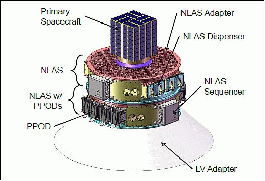
NLAS (Nanosatellite Launch Adapter System)
NASA/ARC (Ames Research Center) and the ORS (Operationally Responsive Space) office of DoD are collaborating to develop NLAS (Nanosatellite Launch Adapter System), which can accommodate multiple CubeSat or CubeSat-derived spacecraft on a single launch vehicle. NLAS is composed of the adapter structure, P-POD (Poly-Picosatellite Orbital Deployer) or similar spacecraft dispensers, and a sequencer/deployer system. 35) 36) 37) 38) 39)
The NLAS Objectives are
• Increase the access to space by having the capability to deploy 8x 3U, 4x 6U or a combination of nanosatellites (1U, 1.5U, 2U, 3U, 6U)
• Provides a modular platform with a configurable sequence and schedule for deploying multiple secondary nano-satellite payloads from launch vehicles.
NLAS is designed to build upon past successful multi-spacecraft launch missions, while protecting the primary spacecraft and mission operator from additional risk exposure from rideshare launches.
NLAS Consists of 3 Major Subsystems
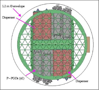
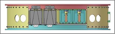
1) Adapter structure. The structure essentially raises the separation plane approximately 26 cm for the primary spacecraft. This dimension was selected to allow P-POD-type dispensers under the top deck, but also to limit the distance that the primary spacecraft must be raised in order to limit unacceptable dynamic loads issues. The structure includes all load bearing elements for the entire system. As it uses a 1.0 m outer diameter, the NLAS adapter is designed to be compatible with both the SpaceX Falcon-1 series, as well as the OSC Minotaur I launchers.
The adapter structure is further designed to accommodate a primary spacecraft on the top deck. By using an isogrid design, configurations for 1.0 m or 38 cm LightBand deployer mechanisms are possible. Final mass allowable for a primary is dependent on the mounting/deployer size used and the launch vehicle selected.
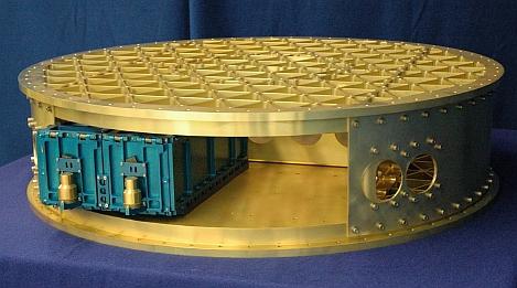
2) Nanosatellite dispensers. As mentioned previously, the Nanosat Missions Office at ARC has larger than CubeSat spacecraft form factors in mind, all of which are derived from the CubeSat modular architecture. The first of these new configurations is roughly a combination of two 3U CubeSats into one 6U form factor. To accommodate the 6U spacecraft, a new dispenser is being introduced into the NLAS architecture. The 6U dispenser occupies the same footprint and uses the same bolt hole mounting pattern as two 3U P-PODs placed side-by-side. If desired, a dividing wall can be configured down the center of the NASA 6U dispenser, and with the exchange of the pusher foot at the rear of the container, CubeSat compatible 3U (or multiple 1U) spacecraft can also be accommodated. Finally, if P-PODs are required, up to 8 can be individually mounted within the adapter structure.
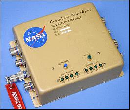
3) Sequencer. Finally, the NLAS also provides an electronic sequencer to release the P-POD or dispenser doors in a pre-determined manner. The sequencer accepts a traditional launch vehicle pyrotechnic signal and then issues separation commands to individual dispensers/P-PODs at the appropriate time. This allows mission designers to optimize deployment operations in order to ensure a low probability of recontact after ejection. The sequencer can forward up to 9 discreet signals; one for each 3U ejector (8), plus one more signal for other sequencers or events. The sequencer is mounted on the external side of the adapter structure. Cables are routed internally to the various dispenser/ejectors. The sequencer has a size of 25 cm x 20 cm x 9.4 cm.
Element | Mass (estimated) | Remarks |
Adapter structure | 85 kg | Structure plus cabling |
Dispensers/P-PODs | 25 kg | Assumes 8 @ 3 kg (3U) |
Spacecraft (nanosatellites) | 48 kg | 6 kg each 3U |
Sequencer | ~2 kg | Not including cabling |
Total | 160 kg | In launch configuration |
NLAS Attributes
• First adapter platform that can deploy up to eight 3U or four 6U CubeSats
• First adapter that can support a 38 cm and a 1.0 m Lightband
• First 3U/6U dispenser using a pinpuller
• First dispenser that can be configured to a 3U or 6U
• First adapter platform to integrate on a Falcon-1e launch vehicle.
Launch
The first NLAS secondary payloads were launched on Nov. 20, 2013 on the ORS-3/STPSat-3 mission from the MARS (Mid-Atlantic Regional Spaceport) on Wallops Island, VA on a Minotaur-1 vehicle of OSC (Orbital Sciences Corporation). The launch was part of the ORS-3 (Operationally Responsive Space-3) enabler launch mission. 40) 41) 42) 43)
Actually, components from two systems - namely Cubestack (of AFRL) and NLAS of NASA/Ames - were used in the successful deployment of the Cubesats from the Nov. 20, 2013 launch on Minotaur-1. From a perspective of NLAS hardware, that launch included: 44)
• 2 NLAS Sequencers and 4 NLAS Dispensers
• The NLAS Sequencers were responsible for commanding the deployment of 28 CubeSats (48U) from 4 NLAS Dispensers and 8 Cal Poly P-PODs.
NASA/Ames developed the NLAS system in coordination with the AFRL’s Space Vehicle Directorate. Ames designed and engineered the NLAS system for broad use, and has shared the design data of NLAS with AFRL. - The launch adapters (or CubeStack adapter structures) that were used for this Minotaur-1 mission were procured by the AFRL from LoadPath LLC of Albuquerque, NM, and of Moog CSA Engineering, Mountain View, CA.
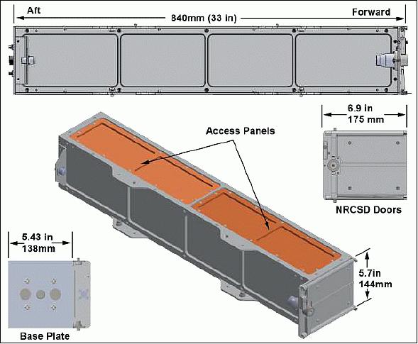
NRCSD (NanoRacks CubeSat Deployer)
NanoRacks LLC of Houston, TX, USA is the developer of the NRCSD and the provider of the NRCSD services. The NRCSD is a self-contained CubeSat deployer system that mechanically and electrically isolates CubeSats from the ISS, cargo resupply vehicles, and ISS crew. The NRCSD design is compliant with NASA ISS flight safety requirements and is space qualified. 45)
The NanoRacks company is unique in owning and marketing its own family of research equipment, both inside and external to the Space Station, and in providing low-cost, high quality services to Station customers. As of July 2014, NanoRacks has deployed over 200 payloads on the Space Station. 46)
Some Background on NanoRacks 47)
NanoRacks LLC was formed in 2009 to provide commercial hardware and services for the U.S. National Laboratory onboard the ISS (International Space Station) via a Space Act Agreement with NASA. 47)
The NanoRacks system is a multipurpose ISS-based research facility designed to host a variety of experiments and activities. The NanoRacks core facility consists of an ER (Express Rack) locker insert . The ER locker insert will be transported to the ISS and placed in the ISS ER Locker. Each NanoRacks ER locker insert holds one NanoRacks tray with a total of 16 CubeLab unit positions with associated CubeLab interfaces. The insert includes a small stowage compartment for interfacing cables, power converter, and NanoRacks tools. A power connector on the NanoRacks insert interfaces with the ER power cable which in turn connects to an ER power connector which provides power to the Nanoracks trays.
The CubeLab experiments will vary in experimental function. It is anticipated they will include, but not be limited to non-powered passive experiments (e.g. radiation dosimeters), crew tended non-powered experiments (e.g. crew testing of an experimental handgrip), powered experiments (e.g. recording accelerometer package), as well, as biological when appropriate.
CubeLab units may be carried to and from the ISS (or disposed of) using a NanoRacks carrier. NanoRacks carriers are foam boxes that can carry any amount of CubeLabs in any available stowage container.
Commercial NanoRacks Platform
NanoRacks Platforms is a multipurpose research facility on board the ISS. NanoRacks Platforms supports NanoRacks Modules in the CubeSat form factor by providing power and data transfer capabilities to operate investigations in microgravity. Each NanoRacks Platform is approximately 43 cm x 23 cm x 50 cm with a mass of approximately 5.4 kg. NanoRacks Platforms are designed for use within the pressurized space station environment. Each platform provides room for up to 16 payloads in the CubeSat form factor to plug effortlessly into a standard USB connector, which provides both power and data connectivity. Its plug and play system uses a simple, standardized interface that reduces payload integration cost and schedule for nanoscale research in microgravity. 48)
Onboard the ISS, NanoRacks Platforms are installed in EXPRESS Rack inserts to supply power and USB data transfer capability for NanoRacks Modules. Each NanoRacks Module must conform to a standard size of approximately 10 cm x 10 cm x 10 cm with a mass of 1 kg. Every NanoRacks Module has a different educational or industrial researcher, the experiments supported cover a wide range of disciplines, some NanoRacks Modules serve as sorties. An ISS crew member powers down the NanoRacks Platform and then plugs in the resupplied NanoRacks Modules. The NanoRacks Platform is powered up, and the data cable between the associated USB port on the NanoRacks Platform front panel and an EXPRESS Laptop computer is plugged in to collect data and download at designated times.
General NanoRacks Operations Protocols 49)
NanoRacks CubeSats/nanosatellites are delivered to the ISS already integrated within a NRCSD (NanoRacks CubeSat Deployer). A crew member transfers each NRCSD from the launch vehicle to the JEM. Visual inspection for damage to each NRCSD is performed. When CubeSat deployment operations begin, the NRCSDs are unpacked, mounted on the JAXA MPEP (Multi-Purpose Experiment Platform) and placed on the JEM airlock slide table for transfer outside the ISS. A crew member operates the JRMS (JEM-Remote Manipulating System) – to grapple and position for deployment. The CubeSats/nanosatellites are deployed when the JAXA ground controllers command a specific NRCSD.
The NRCSD is a rectangular tube that consists of anodized aluminum plates, base plate assembly, access panels and deployer doors. The NRCSD deployer doors are located on the forward end, the base plate assembly is located on the aft end, and access panels are provided on the top. The inside walls of the NRCSD are smooth bore design to minimize and/or preclude hang-up or jamming of CubeSat appendages during deployment should these become released prematurely. However, deployable systems shall be designed such that there is no intentional contact with the inside walls of the NRCSD.
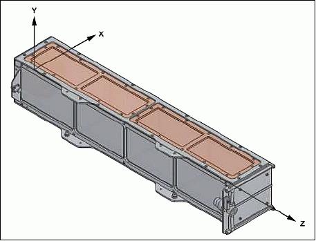
NRCSD coordinate system: The coordinate system of the NRCSD is a right-handed system shown in Figure 33. The +X-axis is orientated as shown in the figure, the +Y axis points out of the top of the NRCSD normal to the access panels, and the +Z-axis points forward to the NRCSD the deployer doors.
Mass properties: The mass property guidelines for CubeSats deployed by NanoRacks are summarized in Table 6. The mass limits are derived from the maximum ballistic number (BN) allowed for ISS deployed payloads. Exceeding these values requires approval by NanoRacks. The CubeSat center of gravity shall be within 2 cm of its geometric center.
Form factor | Maximum mass (kg) |
1U | 2.82 |
2U | 5.657 |
3U | 8.485 |
4U | 11.314 |
5U | 14.142 |
6U | 16.971 |
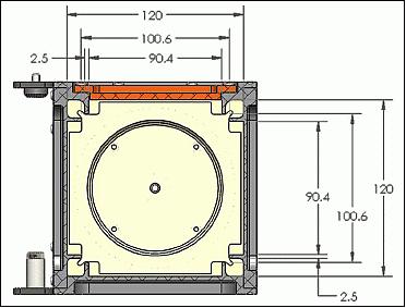
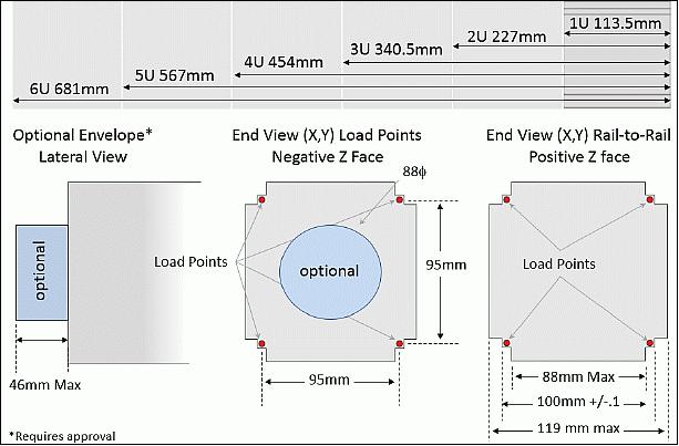
CubeSat dimensional requirements:
The CubeSats nominal envelope maximum dimensions (mm) are shown in Figure 34. No external components other than CubeSat rails or rail roller/slider switch, if used, shall contact the NRCSD interior. Additional envelope provided by a cylindrical recess within the NRCSD pusher plate is available subject to approval.
Electrical interfaces:
The NRCSD does not accommodate an electrical interface to CubeSats. All electrical power shall be internal to the CubeSats. The CubeSat electronics systems design shall adhere to the following requirements.
1) The CubeSat operations shall not begin until a minimum of 30 minutes after deployment from the ISS. Only an onboard timer system may be operable during this 30-minute post deploy time frame.
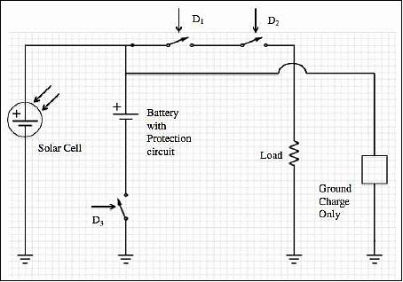
2) The CubeSat electrical system design shall incorporate a minimum of three (3) inhibit switches actuated by physical deployment switches as shown in Figure 36.
3) The CubeSat electrical system design shall not permit the ground charge circuit to energize the satellite systems (load), including flight computer (Figure 36). This restriction applies to all charging methods.
4) RBF (Remove Before Flight) pins are required. Arming switch or captive jumpers may be an acceptable alternative; contact NanoRacks.
5) The RBF pin shall preclude any power from any source operating any satellite functions with the exception of pre-integration battery charging.
6) RBF pins must be capable of remaining in place during integration with NRCSD. It shall not be necessary to remove the RBF to facilitate loading into the NRCSD.
7) All RBF pins, switches, or jumpers utilized as primary electrical system and RBF inhibits must be accessible from the access panels (see Figure 1) for removal at the completion of loading into the NRCSD.
Batteries: CubeSats that utilize on-board batteries shall comply with NASA requirements for battery safety. This requirement applies for main power batteries and for batteries associated with real-time clocks or watch-dog circuits i.e. “coin cell” batteries. Contact NanoRacks for the appropriate battery test procedure. Batteries should maintain charge for a minimum of 6 months from time of integration into the NRCSD by NanoRacks.
References
1) J. Puig-Suari, C. Turner, R. J. Twiggs, “CubeSat: The Development and Launch Support Infrastructure for Eighteen Different Satellite Customers on One Launch,” AIAA/USU Conference on Small Satellites, Aug. 13-16, 2001, Logan, UT, SSC01-VIIIb-5
2) V. M. Aguero, “Cubesats: A Technology and Science Mission Low-cost Test Bed,” AIAA/USU Conference on Small Satellites, Aug. 13-16, 2001, Logan, UT, SSC01-VIIIb-3
3) C. A. Kitts, R. J. Twiggs, “Low Cost Space Missions for Education and Technology Research,” Proceedings of the 21st International Symposium on Space Technology and Science, Omiya, Japan, May 24-31, 1998
4) H. Heidt, J. Puig-Suari, A. S. Moore, S. Nakasuka, R. J. Twiggs, “CubeSat: A new Generation of Picosatellite for Education and Industry Low-Cost Space Experimentation,” AIAA/USU Conference on Small Satellites, Aug. 21-24, 2000, SSC00-V-5, URL: http://www.stensat.org/Publications/SSDL2002.pdf
5) S. Lee, A. Toorian, N. Clemens, J. Puig-Suari, B. Twiggs, “CalPoly Coordination of Multiple CubeSats on the DNEPR Launch Vehicle,” Proceedings of AIAA/USU Conference on Small Satellites, Logan, UT, Aug. 9-12, 2004, SSC04-IX-7
6) Jonathan Brown, Riki Munakata, “Dnepr 2 Satellite Identification and the Mk.III P-POD,” CubeSat Developers' Workshop, San Luis Obispo, CA, USA, April 9-11, 2008, URL: http://mstl.atl.calpoly.edu/~workshop/archive/2008/Spring/Day%202/1420%20-%20Munakata%20-%20Dnepr2.pdf
7) Alexander Chin, Roland Coelho, Lori Brooks, Ryan Nugent, Jorgi Puig-Suari, “Standardization Promotes Flexibility: A Review of CubeSats’ Success,” 6th Responsive Space Conference, April 28–May 1, 2008, Los Angeles, CA, RS6-2008-4006, URL: https://web.archive.org/web/20150607003050/http://www.responsivespace.com/Papers/RS6/SESSIONS/SESSION%20IV/4006_CHIN/4006P.pdf
8) I. Nason, J. Puig-Suari, R. Twiggs, “Development of a Family of Picosatellite Deployers Based on the CubeSat Standard,” Proceedings of the IEEE Aerospace Conference, Big Sky, MT, March 9-16, 2002
9) J. Puig-Suari, C. Turner, W. Ahlgren, “Development of the Standard CubeSat Deployer and a CubeSat Class PicoSatellite,” IEEE, 1 0-7803-6599-2, 2001
10) A. Toorian, E. Blundell, J. Puig-Suari, “CubeSats as Responsive Satellites,” Proceedings of the 2005 Responsive Space 3 Conference, Town Meeting, NASA/JPL, April 28, 2005, AIAA-RS3 2005-3001
11) A. Toorian, K. Diaz, S. Lee, “The CubeSat Approach to Space Access,” Proceedings of the 2008 IEEE Aerospace Conference, Big Sky, MT, USA, March 1-8, 2008, paper: 2.1402
12) M. Swartwout, “University-Class Satellites: From Marginal Utility to 'Disruptive' Research Platforms,” Proceedings of AIAA/USU Conference on Small Satellites, Logan, UT, Aug. 9-12, 2004, SSC04-II-5
13) Jordi Puig-Suari, Kyle Leveque, Victor Aguero, Roland Coelho, Scott Williams, “Enabling Flexible Secondary Launches with the CubeSat Standard,” Proceedings of the 23nd Annual AIAA/USU Conference on Small Satellites, Logan, UT, USA, Aug. 10-13, 2009, SSC09-X-2
14) “Nanosatellite Launch Service,” UTIS/SFL, URL: https://web.archive.org/web/20140228234723/http://www.utias-sfl.net/SpecialProjects/LaunchIndex.html
15) S. Eagleson, K. Sarda, S. Mauthe, T. Tuli, R. E. Zee, “Adaptable, Multi-Mission Design of CanX Nanosatellites,” Proceedings of the 20th Annual AIAA/USU Conference on Small Satellites, Logan, UT, USA, Aug. 14-17, 2006, SSC06-VII-3
16) F. M. Pranajaya, R. E. Zee, “Generic Nanosatellite Bus for Responsive Mission,” 5th Responsive Space Conference, RS5-2007-5005, Los Angeles, CA, April 23–26, 2007, URL: https://web.archive.org/web/20150607212939/http://www.responsivespace.com/Papers/RS5/SESSION%20PAPERS/SESSION%205/5005_PRANAJAYA/5005P.pdf
17) D. D. Kekez, R. E. Zee, F. M. Pranajaya, “SFL Nanosatellite Missions & Nanosatellite Launch Service,” 4th Annual CubeSat Developers' Summer Workshop at the 21st Annual AIAA/USU Conference on Small Satellites, Logan, UT, Aug. 13-16, 2007
18) S. Roemer, S. Stoltz, “SPL – Light Weight Deployment Mechanism for Single CubeSats and DPL for Double CubeSats,” Proceedings of the Symposium on Small Satellite Systems and Services (4S), Funchal, Madeira, Portugal, May 31-June 4, 2010
19) http://www.cubesatshop.com/
21) Abe Bonnema, Michiel van Bolhuis, “Overview and Post-Launch Results from the ISILaunch01 Campaign,” Proceedings of the 60th IAC (International Astronautical Congress), Daejeon, Korea, Oct. 12-16, 2009, IAC-09.D2.2.5
22) “Andrews Space Partners with ISIS to Manufacture EZPODs in the United States,” ISIS, Oct. 11, 2012, URL: http://www.isispace.nl/cms/index.php/news/latest-news/20-news/press-releases/87-ezpods
23) Yosuke Nakamura, Naomi Murakami, Yuta Horikawa, Hiroshi Tachihara, Hiroshi Horiguchi, Keiichi Hirako, Hidekazu Hashimoto, “Vitalization of Japanese Small Satellite Community through Publicity-offered Piggy-back Launch,” Proceedings of the Symposium on Small Satellite Systems and Services (4S), Funchal, Madeira, Portugal, May 31-June 4, 2010
24) Launch Plan of Venus Climate Orbiter (PLANET-C) / Small Secondary Satellites by H-IIA Launch Vehicle No. 17 (H-IIA F17),” March 2010, URL: http://www.jaxa.jp/countdown/f17/pdf/plan_h2af17_e.pdf
25) “Overview of Public Offering for Small Secondary Satellite Launch Opportunity,” JAXA Press Kit, URL: http://www.jaxa.jp/countdown/f17/pdf/presskit_subpayload_e.pdf
26) “Overview of Secondary Payloads,” URL: http://www.jaxa.jp/countdown/f17/overview/sub_payload_e.html
27) Nicholas McGrail, Christina Hicks, Shane Driscoll, Jim Newman, “NPS CubeSat Launcher (NPSCuL) Program Update,” 2009 CubeSat Developer's Summer Workshop, USU (Utah State University, Logan, UT, 2009, URL: https://web.archive.org/web/20160805071249/http://mstl.atl.calpoly.edu/~bklofas/Presentations/SummerWorkshop2009/Sun_1130_NPSCuL%20Presentation%20to%20CubeSat%20Workshop%20Summer%202009.pdf
28) Travis Willcox, “Office of Space Launch Atlas V Aft Bulkhead Carrier & Operationally Unique Technologies Satellite,” 9th Annual Spring CubeSat Developer's Workshop, Cal Poly State University, San Luis Obispo, CA, USA, April 18-20, 2012, URL: https://web.archive.org/web/20190716161058/http://mstl.atl.calpoly.edu:80/~bklofas/Presentations/DevelopersWorkshop2012/Keynote_Willcox_ABC_OUTSat.pdf
29) “ULA Atlas V finally launches with NROL-36,” NASA, Sept. 13, 2012, URL: http://www.nasaspaceflight.com/2012/09/uatlas-v-launch-nrol-36-vandenberg/
30) Amando D. Stein, “NPS CubeSat Prepares to See Space By Way of New Payload Platform,” NPS, May 8, 2012, URL: http://www.nps.edu/About/News/NPS-CubeSat-Prepares-to-See-Space-By-Way-of-New-Payload-Platform-.html
31) Guy Mathewson, “2012 CubeSat Workshop, OSL’s Vision & Mission,” 9th Annual Spring CubeSat Developer's Workshop, Cal Poly State University, San Luis Obispo, CA, USA, April 18-20, 2012, URL: http://mstl.atl.calpoly.edu/~workshop/archive/2012/Spring/01-Mathewson-Keynote.pdf
32) Travis Willcox, “Office of Space Launch Atlas V Aft Bulkhead Carrier & Operationally Unique Technologies Satellite,” 9th Annual Spring CubeSat Developer's Workshop, Cal Poly State University, San Luis Obispo, CA, USA, April 18-20, 2012, URL: http://mstl.atl.calpoly.edu/~workshop/archive/2012/Spring/35-Wilcox-NationalReconsisanceOffice.pdf
33) Travis Willcox, “Atlas V Aft Bulkhead Carrier Rideshare System,” Proceedings of the 2012 IEEE Aerospace Conference, Big Sky, Montana, USA, March 3-10, 2012
34) Ryan Hevner, Walter Holemans, Jordi Puig-Suari, Robert Twiggs, “An Advanced Standard for CubeSats,” Proceedings of the 25th Annual AIAA/USU Conference on Small Satellites, Logan, UT, USA, Aug. 8-11, 2011, paper: SSC11-II-3, URL: file:///C:/profiles/HERBER~1/LOKALE~1/Temp/SSC11-II-3-1.pdf
35) Bruce D. Yost, John W. Hines, Elwood F. Agasid, Steven J. Buckley, “Nanosatellite Launch Adapter System (NLAS),” Proceedings of the AIAA/8th Responsive Space Conference, March 8-11, 2010, Los Angeles, CA, USA, paper: AIAA-RS8-2010-5004, URL: http://ntrs.nasa.gov/archive/nasa/casi.ntrs.nasa.gov/20100033805_2010036951.pdf
36) “NASA Ames Small Satellite Briefing,” URL: http://www.censec.dk/Admin/Public/Download.aspx?file=Files%2fFiler%2fCenSec%2fKonference%
2f2011%2fSmall+Sat+Briefing_V4.pdf
37) “NASA-Built Nanosatellite Launch Adapter System Ready For Flight,” Space Daily, May 31, 2013, URL: http://www.spacedaily.com/.../NASA_Built_Nanosatellite_Launch_Adapter_System_Ready_For_Flight
38) “Nanosatellite Launch Adapter System (NLAS),” NASA, April 30, 2013, URL: http://www.nasa.gov/centers/ames/engineering/projects/nlas.html#.UqKt5SeFf_o
39) James Chartres, “Nano-Satellite Launch Adapter System (NLAS) – Overview,” Proceedings of the 11th Annual CubeSat Developers’ Workshop - The Edge of Exploration,” San Luis Obispo, CA, USA, April 23-25, 2014, URL: http://www.cubesat.org/images/cubesat/presentations/DevelopersWorkshop2014/Chartres_NLAS.pdf
40) “Orbital Successfully Launches Minotaur I Rocket Supporting ORS-3 Mission for the U.S. Air Force,” Orbital, Nov. 19, 2013, URL: http://www.orbital.com/NewsInfo/release.asp?prid=1876
41) Patrick Blau, “Minotaur I successfully launches STPSat-3 & record load of 28 CubeSats,” Spaceflight 101, Nov. 20, 2013, URL: http://www.spaceflight101.com/minotaur-i-ors-3-launch-updates.html
42) Jushua Buck, “NASA Helps Launch Student-Built Satellites as Part of CubeSat Launch Initiative,” NASA Release 13-343, Nov. 20, 2013, URL: http://www.nasa.gov/press/2013/november/nasa-helps-launch-student-built-satellites-as-part-of-cubesat-launch-initiative/#.UqF8qieFf_o
43) Bryan Klofas, “Upcoming CubeSat Launches: The Flood Has Arrived,” AMSAT-NA Symposium, Houston, Texas 1 November 2013, URL: http://www.klofas.com/papers/klofas_amsat2013.pdf
44) Information provided by Joshua M. Buck of NASA/HQ, Washington D.C.
45) “NanoRacks CubeSat Deployer (NRCSD) Interface Control Document,” NanoRacks, Document: NR-SRD-029, Dec. 10, 2013, URL: https://web.archive.org/web/20140819090606/http://nanoracks.com/wp-content/uploads/Current_edition_of_Interface_Document_for_CubeSat_Customers.pdf
46) “Orbital Sciences’ Successfully Berthed Cygnus to ISS in Second Resupply Mission,” NanoRacks Press Release, July 6, 2014, URL: http://nanoracks.com/wp-content/uploads/NanoRacks-Release-26-Cygnus-Successfully-Berthed-to-ISS.pdf
47) Nonreimbursable Space Act Agreement between NanoRacks LLC and NASA for operation of the NanoRacks systems aboard the International Space Station National Laboratory,” NASA, Sept. 2009, URL: http://www.nasa.gov/pdf/387938main_SAA_SOMD_6355_Nanoracks_ISS_National_Lab.pdf
48) “NanoRacks Platforms,” NASA, July 15, 2014, URL: http://www.nasa.gov/mission_pages/station/research/experiments/829.html#images
49) “NanoRacks-Microsized Microwave Atmospheric Satellite (NanoRacks-MicroMAS),” NASA, July 15, 2014, URL: http://www.nasa.gov/mission_pages/station/research/experiments/1330.html#operations
The information compiled and edited in this article was provided by Herbert J. Kramer from his documentation of: ”Observation of the Earth and Its Environment: Survey of Missions and Sensors” (Springer Verlag) as well as many other sources after the publication of the 4th edition in 2002. - Comments and corrections to this article are always welcome for further updates (eoportal@symbios.space).