CSES (China Seismo-Electromagnetic Satellite)
EO
Space environment
Gravity and Magnetic Fields
Gravity, Magnetic and Geodynamic measurements
Quick facts
Overview
| Mission type | EO |
| Agency | CNSA, ASI |
| Mission status | Operational (nominal) |
| Launch date | 02 Feb 2018 |
| Measurement domain | Gravity and Magnetic Fields |
| Measurement category | Gravity, Magnetic and Geodynamic measurements |
| Measurement detailed | Electron Energy and Pitch Angle Distribution |
| Instruments | HEPD |
| Instrument type | Space environment |
| CEOS EO Handbook | See CSES (China Seismo-Electromagnetic Satellite) summary |
CSES (China Seismo-Electromagnetic Satellite) / Zhangheng 1
CSES is a Chinese-Italian scientific mission dedicated to monitoring electromagnetic field and waves, plasma and particles perturbations of the atmosphere, ionosphere and magnetosphere induced by natural sources and anthropocentric emitters; and to study their correlations with the occurrence of seismic events. In general, CSES mission will investigate the structure and the dynamic of the topside ionosphere, the coupling mechanisms with the lower and higher plasma layers and the temporal variations of the geomagnetic field, in quiet and disturbed conditions. Data collected by the mission will also allow studying solar-terrestrial interactions and phenomena of solar physics, namely CMEs (Coronal Mass Ejections), solar flares and cosmic ray solar modulation. 1)
The satellite mission is part of a collaboration program between the CNSA (China National Space Administration) and ASI (Italian Space Agency), and developed by CEA (China Earthquake Administration) and INFN (Italian National Institute for Nuclear Physics), together with several Chinese and Italian Universities and research Institutes. CSES is the first satellite of a space monitoring system proposed in order to investigate the topside ionosphere - with the most advanced techniques and equipment - and designed to gather world-wide data of the near-Earth electromagnetic environment. The data will contribute to provide an observational sharing service for international cooperation and the scientific community.
Zhangheng-1, named after the Chinese polymath, astronomer and pioneering seismologist Zhang Heng (CE 78–139), is designed to remain in orbit for five years and record the electromagnetic situation of earthquakes above 6 magnitude in China and quakes above 7 magnitude all over the world.
The Chinese institutes involved in the project are CNSA (China National Space Administration), CEA (China Earthquake Administration) , LIP (Lanzhou Institute of Physics), ICD-CEA (Institute of Crustal Dynamics), IHEP (Institute of High Energy Physics), NSSC (National Space Science Center), CSSAR/CAS (Center for Space Science and Applied Research/Chinese Academy of Science), the Space Star Technology Co. and the DFH Satellite Co.
Italy participates in the CSES satellite project with the LIMADOU project - funded by ASI and INFN - through a collaboration that includes several INFN Divisions (Bologna, Naples, Perugia, Roma Tor Vergata), the INFN Center TIFPA of Trento, the INFN National Laboratories of Frascati, the Universities of Trento, Roma Tor Vergata, Uninettuno and the Institutes INAF-IAPS (Italian National Institute of Astrophysics and Planetology) and INGV (Italian National Institute of Geophysics and Volcanology).
Scientific objectives
The lithosphere-atmosphere-ionosphere coupling is a complex subject involving many physical effects and interactions that occur from the Earth surface up to the magnetosphere. The investigation of such coupling mechanisms - and in particular of the, partially unknown, behavior of the ionosphere-magnetosphere transition region - is of fundamental importance for Earth remote sensing, monitoring of the near-Earth electromagnetic environment and studying of natural hazards. A great part of these effects is caused by natural non-seismic and anthropogenic electromagnetic emissions, but of particular relevance are the electromagnetic disturbances associated with the seismic activity that can produce ionospheric perturbations as well as the precipitation of particles from the Van Allen belts, observed before, during and after earthquakes of medium and strong magnitude. All of these phenomena must be distinguished from those induced by sources external to the geomagnetic cavity and by atmospheric events. In fact, an important role in controlling the dynamic of the topside ionosphere is played by the Sun – that generates (regular and irregular) variations of the lithosphere-ionosphere-magnetosphere parameters by impulsive events as solar Coronal Mass Ejections and Solar Flares – as well as by tropospheric activity (lightning, TLE, etc.)
Many experimental observations have been performed and theoretical models have been proposed in order to analyze and discriminate ionospheric disturbances caused by natural terrestrial events, such as earthquakes and volcanic eruptions, and by anthropogenic activities.
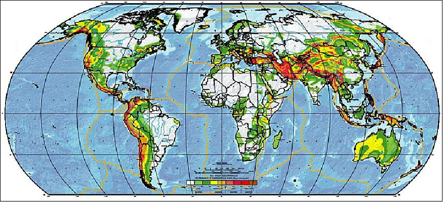
Seismicity is one of the consequence of the dynamic processes that take place inside the Earth's lithosphere. The study of the physical conditions which give rise to an earthquake, as well as of the processes that precede a seismic rupture, constitutes the basis of earthquake prediction approaches.
A recently proposed mission to study seismic precursors is to carry out measurements of the ionospheric anomalies by instruments installed on board satellites. Currently, only the dedicated DEMETER French mission (2004-2006) has collected detailed data; other previous results were obtained by analyzing observations of some not dedicated space experiments.
The objective of the CSES mission is to study the ionospheric disturbances induced by seismic activity and earthquake preparation mechanisms. It is based on long-term systematic and detailed measurements performed by detectors specifically designed. In particular, the mission aims at analyzing the temporal correlation between seismic events and occurrence of electromagnetic perturbations in the upper ionosphere and precipitations of Van Allen particles. Furthermore, CSES will provide important information on ionosphere parameters and on the unknown behavior of the ionosphere-magnetosphere transition region, in order to develop physical models of lithosphere-atmosphere-ionosphere coupling mechanism.
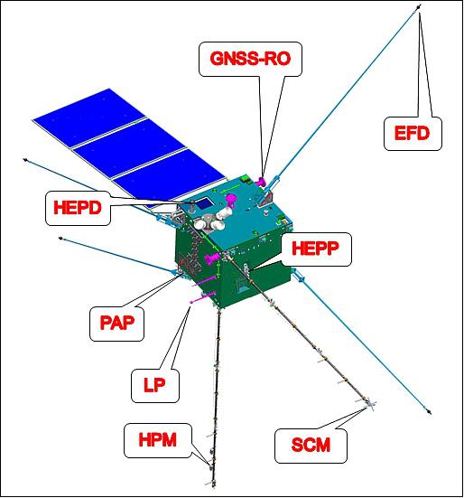
Spacecraft
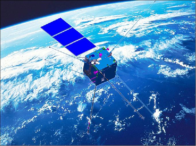
CSES is a 3-axes stabilized satellite, based on the Chinese CAST2000 platform, with a mass of about 730 kg, a size of 1.4 x 1.4 x 1.4 m, and is fitted with a lone deployable solar array. It has a peak of power consumption of about 900 W. Scientific data will be transmitted in X-band at 120 Mbit/s. The expected lifetime is 5 years.
Launch
The CSES satellite was launched on 2 February 2018 (07:51 UTC) on a Long March 2D vehicle from the JSLC (Jiuquan Satellite Launch Center), China. 2) 3)
Orbit: Sun-synchronous orbit, altitude of ~500 km, inclination of ~97.32º, period = 94.6 minutes, revisiting period = 5 days, LTDN (Local Time on Descending Node) at 14 hours.
Secondary Payloads
• Fengmaniu 1, a 3U CubeSat (3 kg), an Earth observation satellite (a technology demonstrator), developed by Link Space Aerospace Technology, Group, Beijing, China. It will also be used as a repeater for amateurs worldwide via the onboard transponder system.
• GOMX-4A, a 6U CubeSat built at GOMSpace for the Danish Ministry of Defence.
• GOMX-4B, a 6U CubeSat built at GOMSpace for ESA.
• NuSat 4 and NuSat-5, Earth observation microsatellites (each 37 kg) of Satellogic S.A., Argentina
• Shaonian Xing (Youth Star), a 2U CubeSat, developed by young students and sponsored by CAST (China Association for Science and Technology).
Mission Status
• November 30, 2019: China's first seismo-electromagnetic satellite Zhangheng 1 has obtained fruitful electromagnetic data, according to the China Aerospace Science and Technology Corporation (CASC). 4)
- The satellite has enabled China to obtain a global geomagnetic map and an ionospheric map with its own intellectual property rights.
- It has obtained information about global ground artificial sources, magnetic storms and signals of earthquakes above 7 magnitude. It also helps with understanding the coupling mechanisms of the lithosphere, atmosphere and ionosphere.
- Shen Xuhui, the chief scientist of the satellite, said China is expected to have three electromagnetic satellites in orbit by 2022, offering support for earthquake forecasting as well as space weather monitoring and warning.
- Developed by DFH Satellite Co., Ltd. under the CASC, the satellite Zhangheng 1 was launched on Feb 2, 2018.
- The satellite was named after Zhang Heng, a renowned scholar of the East Han Dynasty (AD 25-220), who pioneered earthquake studies by inventing the first-ever seismoscope in the year 132.
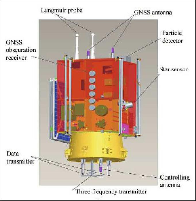
Sensor Complement
The sensor complement will collect measurements in the magnetic latitude range of ±65°. At higher latitudes (in the platform adjustment regions), all detectors are planned to be switched off, in order to perform the activities of the satellite AOCS (Attitude and Orbit Control Subsystem). Each instrument will collect data in two operating modes: ‘‘burst mode'' and ‘‘survey mode". The burst mode is usually activated when the satellite passes over the China territory and the regions with the strongest seismic activities in the world. The survey mode is planned for other areas of the Earth.
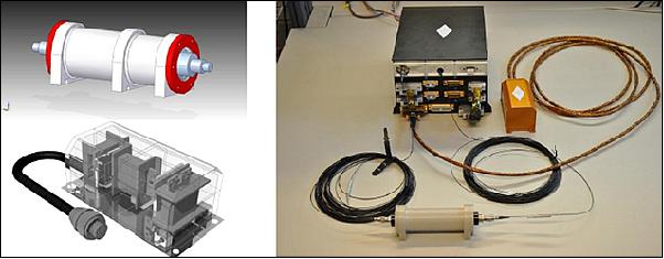
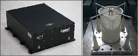
HEPD (High-Energy Particle Detector)
The HEPD instrument is being developed by the Italian side of the CSES collaboration with the objective to measure electrons (3 - 100 MeV) and protons (30 - 300 MeV) in orbit. The instrument consists of a segmented layer of plastic scintillators for the trigger and a calorimeter constituted by a tower of plastic scintillator counters and a LYSO (Lutetium Yttrium Orthosilicate) plane. The direction of the incident particle is provided by two planes of double-side silicon micro-strip detectors placed in front of the trigger. 5) 6) 7) 8)
The HEPD has been designed to measure electron fluxes in the inner Van Allen belt. Electrons with energies up to tens of MeV are stably trapped within the geomagnetic field, forming two belts. Additional transient electron belts are also possible, as recently observed.9) Electromagnetic waves, circularly polarized, with very low and ultra low frequency (VLF/ULF), propagate as Alfven disturbances along the geomagnetic field lines, and have resonant interaction with the trapped electrons.
Free field of view, Pointing | ≥70º, Zenith |
Operating temperature | –10º ± 45º |
Mass budget, Power budget | ≤45 kg, ≤43 W |
Overall dimensions | 20 x 20 x 40 cm3 |
Scientific data bus, Data handling bus | RS-422, CAN 2.0 |
Reliability | 0.99 |
Operating modes, Lifetime | Survey and Burst, ≥5 years |
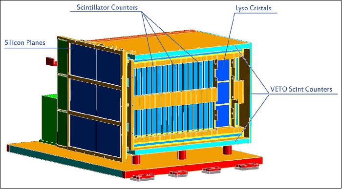
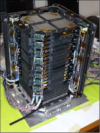
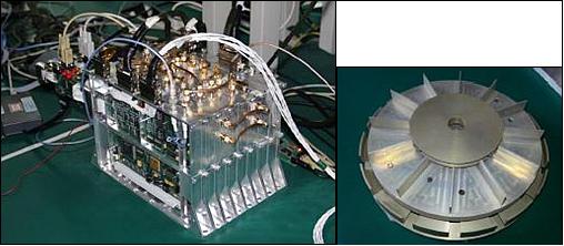
The HEPD is composed by four sub-detectors and the electronics subsystems:
• the tracker, made of two planes of double-side silicon micro-strip sensors. It is located at the top of the instrument, in order to measure the direction of the incident charged particles. Each tracker plane includes 3 ladders made of 2 modules (each module is 106.6 x71.6 x 0.3 mm3), and read out by twelve VLSI chips, six for each dimension. The tracker read-out system has 72 VLSI for a total of 4608 channels. The signal digitization is performed by an ADC board before the signal transmission to the DAQ system for elaboration;
• the trigger system, which is made of one layer of plastic scintillator (20 x 18 x 0.5) cm3, divided into 6 segments with dimensions (20 x 3 x 0.5) cm3. Each segment is read by two Hamamatsu PMTs (PhotoMultiplier Tubes). The trigger system sits below the tracker and at the top of the calorimeter. The trigger requires the coincidence of signal from one of the trigger system segments and from one PMT in the first calorimeter plane. Other trigger combinations can also be used;
• the range calorimeter, which consists of two parts. The first part, on the top, is made with 16 plastic scintillator planes, each of which is 1cm thick and with a side of 15 cm. Every plane is read out by two Hamamatsu PMTs, which are placed at two opposed corners of the plane. The bottom part of the calorimeter consists of a layer with 9 LYSO crystals. These have a height of 4 cm and a side of 5 cm, and each of them is read out by a PMT. The upper calorimeter part allows us to measure both the energy deposition and the range of the impinging particles. The bottom one provides a larger matter thickness, to increase the operational energy range;
• the veto system, consisting in five plastic scintillator counters, 5 mm thick, read out by two PMTs. Four of the veto counters are located at the sides of the instrument, in order to acquire only charged particles with trajectories fully inside the calorimeter, while the fifth one is below the LYSO layer, to reject particles which are not fully contained within the calorimeter, or up-going charged background;
• the electronics subsystem (ELS), inserted in a box placed at one side of the detector. The ELS includes: the CPU, the silicon detector DAQ, the PMTs trigger and acquisition, the LV Control Board, the High Voltage Power Supply (HVPS), the Main power DC/DC converter (LVPS) and 6 mechanical modules.
All the electronics of the HEPD is designed with embedded "Hot/Cold" redundancy and all the components of the board have been selected capable to withstand a -40ºC to 85ºC operating range. The trigger rate and the data stored has to cope with maximum data transfer rate from the satellite, which is 50 GB per day. The electronic system can be schematized into three blocks:
- Silicon detector;
- Scintillator detectors (trigger, energy and veto detectors);
- Global control and data managing.
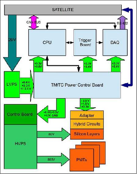
Each detector block includes power chain for bias distribution and a data acquisition processing chain. The main Power Supply provides the low voltages to the detector electronics and the high bias voltages for PMTs and silicon modules. The whole electronics system is depicted in Figure 6. It is composed by front-end electronics and four main boards:
- Data Acquisition (DAQ) Board: manages all the scientific data of HEPD. The DAQ accomplishes the following functionalities: acquisition of trigger signal from PMT/Trigger board, management of hybrid circuits on the silicon planes, acquisition of silicon planes data, computing of PMTs data and silicon planes data, data compression, transmission of scientific data on the scientific data link.
- Trigger Board: manages the analog signals coming from the PMTs and generates the trigger signals needed for data acquisition. This board also generates trigger signals needed by DAQ Board to start the acquisition procedure. The main functions of the Trigger Board are to acquire the PMTs analog signal using EASIROC (Extended Analog Si-pm Integrated ReadOut Chip) Integrated Circuits and to convert all the EASIROC readout signals into digital signals, to allow the DAQ board to read the EASIROC digital output, to allow the CPU to configure the EASIROC, to generate and transmit "slow" event trigger signals manipulating the "fast" trigger signals coming from EASIROC, to allow the CPU to configure the "slow" trigger generation algorithm.
- CPU Board: controls the detector and communicates with the platform of the satellite via CAN BUS interface. The CPU manages the following functionalities: communication with Satellite OBDH computer via CAN bus, storage of non volatile information, management - via internal "slow" control links bus- of TM/TC and LVPS control board, Trigger Board and DAQ Board, management of system diagnostic routines and of system configuration, system monitor.
- Telemetry/Telecommand board: manages the LVPS that provides bias to the electronics subsystems, the local telemetry and telecommand signals.
All the logic has been realized with flash FPGA to improve radiation hardness.
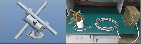
EFD (Electric Field Detector)
The objective of EFD is to measure the variation of the ionosphere electric field due to perturbations from solar, seismic and anthropic phenomena. It consists of about four meter long independent identical sensors installed at the tips of four booms (~ 4 m long) and it has been designed in collaboration between the LIP (Lanzhou Institute of Physics)of CAST and the INFN division of Roma Tor Vergata. Two different engineering models have been designed and tested in the Faraday Cage at the INFN division of Roma Tor Vergata, and in the Plasma Chamber at the IAPS-INAF Institute in Roma Tor Vergata.
The EFD Flight Model, assembled by the LIP (Lazhou Institute of Physics), has been optimized taking into account the performance of the two instruments.
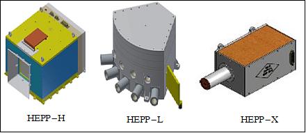
HEPP (High-Energy Particle Package)
The HEPP instrument package is being developed at the IHEP/CAS (Institute of High Energy Physics /Chinese Academy of Sciences) of Beijing. The package consists of a high-energy (HEPP-H), a low-energy detector (HEPP-L) and a solar X-ray detector (HEPP-X).
Item | HEPP-H | HEPP-L | HEPP-X |
Main technology | Silicon strip detector + Cst calorimeter | Silicon semiconductor telescope array | Silicon MDC detector |
Geometric factor | e: 73-15 cm2 sr, p: 90-33 cm2 sr | 3.52 cm2 sr | - |
Energy channels | e: 256, p: 256 | e: 256, p: 256 | 2048 |
Energy range | e: 2-50 MeV; p: 15-200 MeV | e: 0.1-3 MeV, p: 2-20 MeV | 1-20 keV |
Energy resolution (typical value) | 10% | 10% | 300 eV @ 5.9 keV |
Angular resolution (typical value) | 5º | 5º | - |
HPM (High-Precision Magnetometer)
The HPM is an optically-pumped absolute scalar magnetometer which is based on two-photon spectroscopy of free alkali atoms. In a special laser based excitation mode, three different magnetic field dependent resonances arise in the presence of an external magnetic field. They reach their maximal strengths at different angles between the magnetic field direction and the reference axis of the sensor which is defined by the optical path of the laser excitation field. Dependent on this angle, the strongest resonance is selected for the actual measurement which enables an omnidirectional scalar magnetometer.
Main parameters:
- Frequency Range: DC-15 Hz
- Resolution: 0.15 nT
- Sensitivity: 0.05 nT·Hz- 1/2 @ 1 Hz
SCM (Search-Coil Magnetometer)
The Search-Coil Magnetometer (SCM) measures the magnetic field fluctuations in ionosphere.
Main parameters:
- Band: 10 Hz - 20 kHz
- Magnitude: 5×10⁻⁴- 50 nT
- Sensitivity: 1 nT·Hz- 1/2 @ 2 kHz
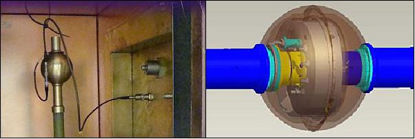
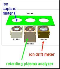
PAP (Plasma Analyzer Payload)
The Plasma Analyzer measures the plasma parameters, including ion density, ion temperature, ion drift velocity, ion composition and ion density fluctuation, for searching:
- the coupling between ionosphere and seism
- the ionospheric physics
The PAP , shown in Figure 11, consists of three different ion analyzers (ion capture meter, retarding potential analyzer, and ion drift meter), mechanically fixed on a conducting plate. The Plasma Analyzer has been tested in the INAF-IAPS Plasma Chamber.
Parameter | Performance |
Ion composition | H+, He+, O+ |
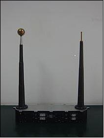
LP (Langmuir Probe)
The Langmuir Probe, realized by the Center for Space Science and Applied Research of the Chinese Academy of Science, allows to:
- monitor the global parameters of the ionosphere in situ
- study the coupling between lithosphere and ionosphere before, during and after earthquakes.
The LP consists of a pair of spherical Langmuir Probes with diameters of 5 cm and 1 cm, respectively, installed at the tip of booms 50 cm long. The LP has been tested in an Electronics test facility for an electronics calibration and in the INAF-IAPS Plasma Chamber.
Quantity | Range |
Electron density | 5 x 10² -107 cm3 |
Tri-Band Beacon
The Tri-Band Beacon is a three-frequency radio beacon developed to provide transmission at VHF/UHF and L-band (150/400/1067 MHz). The primary objective of the Tri-band beacon is to study the electron density in the ionosphere and to produce two-dimensional maps or one-dimensional profiles. The secondary objective is to measure the influence of ionospheric irregularities on VHF, UHF and L-band transmissions from space to ground.
GNSS Occultation Receiver
The GNSS (Global Navigation Satellite Systems) Occultation Receiver is used for ionosphere vertical sounding. In particular, it allows to measure the total electron content (TEC) and to obtain vertical electron density. The main specifications are the following:
- Working Band: GPS L1/L2 & BD B1/B2
- Occultation Channels: (4 for GPS,2 for BD)
- Sample Rate: 20-100 Hz
- TEC System Tomography Accuracy: 10%.
References
1) "CSES Mission," INFN, URL: http://cses.roma2.infn.it/node/18
2) Rui C. Barbosa, "Long March 2D launches Zhangheng-1 Earthquake investigator," NASA Spaceflight.com, 2 Feb. 2018, URL: https://www.nasaspaceflight.com/2018/02
/long-march-2d-zhangheng-1-earthquake-investigator/
3) "China Launches First Seismo-Electromagnetic Satellite Plus Six SmallSats," Satnews Daily, 5 Feb. 2018, URL: http://www.satnews.com/story.php?number=1426399346
4) "China's first electromagnetic satellite bears fruitful results," China Daily, 30 November 2019, URL: http://www.chinadaily.com.cn/a/201911/30/WS5de27b7ca310cf3e3557b227.html
5) Roberta Sparvoli, Francesco Palma, Beatrice Panico, Alessandro Sotgiu, Vincenzo Vitale for the CSES/HEPD collaboration, "The High-Energy Particle Detector on board of the China Seismo-Electromagnetic Satellite," Proceedings of the ‘Living Planet Symposium 2016', Prague, Czech Republic, 9–13 May 2016 (ESA SP-740, August 2016), URL: http://articles.adsabs.harvard.edu/cgi-bin/nph-iarticle_query?2016
ESASP.740E.315S&data_
type=PDF_HIGH&whole_paper=YES&type=PRINTER&filetype=.pdf
6) Xuhui Shen, Lanwei Wang, Shigen Yuan, Xuemin Zhang, Jianjun Wang, Yanyan Yang, "Progress of the China Seismo‐Electromagnetic Satellite (CSES) mission," Proceedings of the ‘Living Planet Symposium 2016', Prague, Czech Republic, 9–13 May 2016 (ESA SP-740, August 2016), URL: http://lps16.esa.int/posterfiles/paper1845/Progress%20of%20th
e%20China%20Seismo-Electromagnetic%20Satellite%20mission.pdf
7) "High-Energy Particle Detector (HEPD)," URL: http://cses.roma2.infn.it/node/30
8) L.Alfonsi, F. Ambroglini,G. Ambrosi, R. Ammendola,D. Assante, D. Badoni, V . A. Belyaev, W .J. Burger, A. Cafagna, P. Cipollone, G. Consolini, L. Conti, A. Contin, E. DeAngelis, C. DeDonato, G. DeFranceschi, A. DeSantis, C. DeSantis, P. Diego, M. Durante, C. Fornaro, C. Guandalini, G. Laurenti, M. Laurenza, I. Lazzizzera, M. Lolli, C. Manea, L. Marcelli, F. Marcucci, G. Masciantonio, G. Osteria, F. Palma, F. Palmonari, B. Panico, L. Patrizii, P. Picozza, M. Pozzato, I. Rashevskaya, M.Ricci, M. Rovituso, V. Scotti, A. Sotgiu, R.Sparvoli, B. Spataro, L. Spogli, F. Tommasino,P. Ubertini, G. Vannaroni, S. Xuhui, S.Zoffoli, The CSES-LIMADOU Collaboration, "The HEPD particle detector and the EFD electric field detector for the CSES satellite," Radiation Physics and Chemistry, Volume 137, August 2017, Pages 187-192, https://www.sciencedirect.com/science/article/pii/S0969806X16308301?via%3Dihub
9) Yuri Y. Shprits, Dmitriy Subbotin, Alexander Drozdov, Maria E. Usanova, Adam Kellerman, Ksenia Orlova, Daniel N. Baker, Drew L. Turner, Kyung-Chan Kim, "Unusual stable trapping of the ultrarelativistic electrons in the Van Allen radiation belts," Nature Physics Letters, Vol 9, November 2013, URL: https://www.nature.com/articles/nphys2760.pdf
10) V. Scotti, G. Osteria, "The electronics and trigger system of the High Energy Particle Detector (HEPD) onboard the China Electromagnetic Satellite (CSES)," Proceedings of Science, 35th International Cosmic Ray Conference - ICRC2017-10-20 July, 2017, Bexco, Busan, Korea, URL: https://pos.sissa.it/301/248/pdf
The information compiled and edited in this article was provided by Herbert J. Kramer from his documentation of: "Observation of the Earth and Its Environment: Survey of Missions and Sensors" (Springer Verlag) as well as many other sources after the publication of the 4th edition in 2002. - Comments and corrections to this article are always welcome for further updates (eoportal@symbios.space).