COSMO-SkyMed
EO
Land
Multi-purpose imagery (land)
Land surface imagery
COSMO-SkyMed (Constellation of Small Satellites for Mediterranean basin Observation) is a 4 spacecraft constellation, with the first two launched in 2007, and the remaining two launched in 2008 and 2010 respectively. The mission is jointly funded by the Italian Ministry of Research and the Italian Ministry of Defence , and developed by Agenzia Spaziale Italiana (ASI), for the purpose of both military and civil (research and commercial) data use. Starting in 2018, COSMO-SkyMed Second Generation (CSG) has provided continuity for COSMO-SkyMed.
Quick facts
Overview
| Mission type | EO |
| Agency | MoD (Italy), ASI |
| Mission status | Operational (extended) |
| Launch date | 08 Jun 2007 |
| Measurement domain | Land, Snow & Ice |
| Measurement category | Multi-purpose imagery (land), Vegetation, Landscape topography, Sea ice cover, edge and thickness, Snow cover, edge and depth |
| Measurement detailed | Land surface imagery, Vegetation type, Land cover, Land surface topography, Sea-ice cover, Snow cover, Sea-ice type, Glacier motion, Glacier cover, Soil type |
| Instruments | SAR 2000 |
| Instrument type | Imaging microwave radars |
| CEOS EO Handbook | See COSMO-SkyMed summary |
Related Resources

Mission Capabilities
Each of the 4 satellites is equipped with the SAR-2000 Synthetic Aperture Radar, which observes in the X-band to provide global observation under all weather and visibility conditions. The instrument is composed of 2 major elements: the phased array antenna subsystem, known as SAA (SAR Active Antenna) and the central electronics module, known as SIE (SAR Internal Electronics).
The programmable antenna enables Stripmap, ScanSAR and Spotlight operational acquisition modes. The multiple sub-aperture configuration additionally allows for Wide Area Surveillance, Continuous Imaging and High Resolution Imaging modes. This multi-modal acquisition supports the dual-use (military and civil) nature of the system as the instrument caters for a range of spectral resolutions and coverage, as determined by user input.
Performance Specifications
The SAR-2000 instrument featured on the COSMO-SkyMed satellites allows for multimodal acquisition. The type of image acquired is determined by the characteristics of the transmitted pulses and the echo signal from the antenna. The ‘Spotlight’ operational mode has a spatial resolution of less than 1m for a spot observation area of 10 x 10m, whereas the ‘Stripmap’ mode has a spatial resolution of 3-15m and swath width of 40km. The two ScanSAR modes (Wideregion and Hugeregion) allow for a larger view region with swath widths of 100km and 200km respectively, however have a spectral resolution of 30m and 100m respectively.
In a 24 hour time period, the maximum acquisition capability is 1800 images - 75 Spotlight plus 375 Stripmap, or 150 ScanSAR images for each satellite. The data acquisition quantity can differ depending on the request of users, including the Crisis Support or Very Urgent system operative modes.
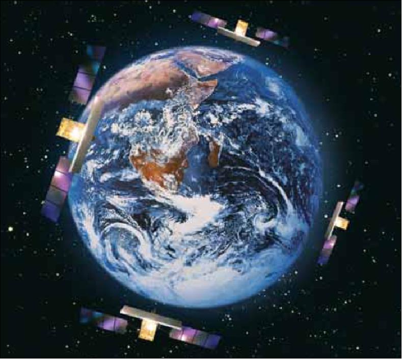
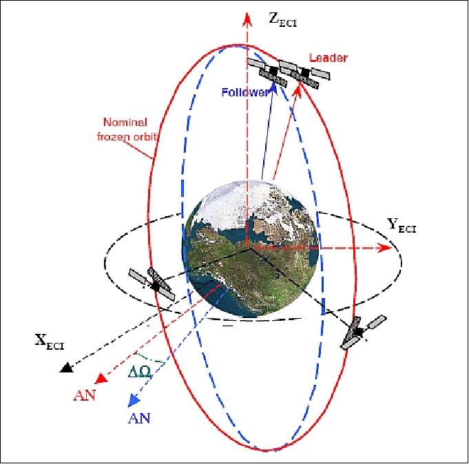
The satellites undergo a sun-synchronous dawn-dusk orbit with a period of 97 minutes, at a nominal altitude of 619km. The constellation can be operated in two basic configurations; the ‘nominal orbital configuration’ where the 4 satellites are equally spaced in the same orbital plane or the ‘interferometric orbital configuration’. The interferometric configuration can feature either 2 satellites in the same plane with close proximity or 2 satellites in phase on slightly varying orbital planes. This configuration enables 3D SAR imagery by combining 2 radar measurements of the same target.
Space and Hardware Components
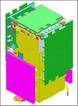
Each spacecraft is three-axis stabilised, consisting of the main body (bus), two deployable solar arrays, and a SAR antenna. The bus provides support functions such as Attitude and Orbit Control System (AOCS), electrical power, data handling, thermal control, radio frequency (RF) communications and on-orbit propulsion. The electrically steerable multi-beam antenna concentrates the transmitted energy into narrow beams in the cross track direction to operate the SAR transmitter/receiver system. The solar arrays have a combined area of 18.3 m^2 and provide a minimum power of 4kW beginning-of-life (BOL) using triple-junction solar cells.
The mass of each spacecraft is approximately 1700 kg. Each has a design life of 5 years with an onboard operational autonomy period of 24 hours.
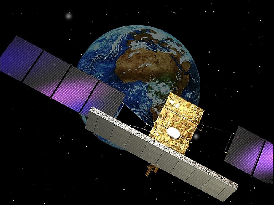
COSMO-SkyMed (Constellation of 4 SAR Satellites)
Spacecraft Launch Mission Status Sensor Complement Ground Segment References
COSMO-SkyMed (Constellation of Small Satellites for Mediterranean basin Observation) is a 4-spacecraft constellation, conceived by ASI (Agenzia Spaziale Italiana), and funded by the Italian Ministry of Research (MUR) and the Italian Ministry of Defense (MoD), Rome, Italy. The program is managed in cooperation of ASI and MoD. The contract was assigned to an Italian industrial team, that is in charge of the project development. Thales Alenia Space Italia (TAS-I) is the prime contractor of the end-to-end system and leads an industrial team of small and medium sized Italian companies including many from the Finmeccanica group. Telespazio is the main Ground Segment contractor responsible for the development of the control center for the constellation, and of the user's ground segments for acquiring, processing and distributing the data gathered by the satellites for civil and defence applications. -The COSMO-SkyMed program represents the largest Italian investment in space systems for Earth Observation.
Each of the four satellites is equipped with a SAR (Synthetic Aperture Radar) instrument and is capable of operating in all visibility conditions at high resolution and in real time. The overall objective of this program is global Earth observation and the relevant data exploitation for the needs of the military community as well as for the civil (institutional, commercial) community.
Sample applications of COSMO-SkyMed data are seen the following fields:
• Defense and security applications: Surveillance, intelligence, mapping, damage assessment, vulnerability assessment, target detection/localization
• Risk management applications: Floods, droughts, landslides, volcanic/seismic, forest fire, industrial hazards, water pollution
• Other applications: Marine and coastal environments, agriculture, forestry, cartography, environment, geology and exploration, telecommunication, utilities and planning
• Provision of commercial imaging services
• The high revisit frequency offered by the four X-band SAR spacecraft is also expected to provide a unique potential to the operational meteorological user community through provision of ancillary data and/or data on meteo-correlated phenomena, in particular as regards sea ice monitoring and study of ocean wave patterns.
• A strong emphasis is given to the dual-use (civil and military) nature of the system. The IEM (Interoperability, Expandability and Multi-sensoriality) concepts are also stressed, since these qualities bring COSMO-SkyMed to be a versatile system able to expand its architecture toward a set of "Partner missions."
Background
In 1996 the Italian Government provided initial funding for the realization of a national Earth observation program. In 1997 the general guidelines for the 1998-2002 Italian National Space Plan (PSN) were approved including the activities on Earth observation. The strategic element in this plan is the COSMO-SkyMed dual-use program of ASI. 1) 2)
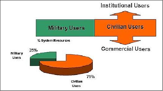
In the summer of 2001, the Italian Ministry of Defense became a partner in the COSMO-SkyMed program (a welcome funding partner for the Italian Ministry of Research). However, the dual-use nature of the COSMO-SkyMed program, i. e. civil (research and commercial) and military use of its data products, resulted in a virtually classified program. A great disadvantage of the new arrangement is that rather sparse technical information of the mission can only be made available to the public. - The funding the the COSMO-SkyMed program is split between ASI and I-MOD with 75% and 25%, respectively, of the system resources distribution.
In this arrangement, Civilian (Scientific, Institutional and Commercial) and Military users share system resources under appropriate regulations. ASI manages and coordinates institutional and scientific users allowing the utilization of the service for acquisitions and products ordering by mean of the COSMO-SkyMED website, whereas the commercial users can access at the system through the commercial provider e-Geos, an ASI-Telespazio Company.
Although the first generation constellation satellite SAR instruments (SAR-2000) will observe in X-band (9.6 GHz with a wavelength of 3.1 cm), multi-mode scenarios (X-, C- L- and P-band) are planned for the future.
The overall system architecture is composed of a space segment, a constellation of SAR satellites, and a ground segment including full featured user services. The requirements call for the following general performance characteristics: 3) 4)
• Full global observation coverage with all weather, day/night acquisition capability
• Collection capability of large areas within a single pass, with along-track stereo imaging during a single pass
• High image quality, to allow a robust image interpretability at the requested scale of analysis (data sets are characterized by adequate spatial and spectral resolution suitable to perform analyses at different scales of detail)
• Ground track repeatability: the satellites of the SAR constellation shall have a ground track repeatability of better than 1 km
• Fast response times (from the data/service user request up to the data/service delivery to that requiring user).
The SABRINA project was started in 2004/5.
Space Segment
The COSMO-SkyMed space segment is composed of a constellation of four SAR satellites. The PRIMA [Piattaforma Riconfigurabile Italiana Multi-Applicativa (Reconfigurable Italian Platform for Multiple Applications)] bus of Alcatel Alenia Space is being employed. TAS-I (Thales Alenia Space-Italia) is also the prime contractor of the space segment [funding by ASI and MoD (Ministry of Defense)].
Note: As of April 10, 2007, the EC approved the transfer to Thales of Alcatel-Lucent's shareholdings in the two space sector joint venture companies Alcatel Alenia Space and Telespazio. Hence, Alcatel Alenia Space was renamed to Thales Alenia Space.
Each COSMO-SkyMed spacecraft is three-axis stabilized, consisting of the main body (bus), two deployable solar arrays, and a SAR antenna. The bus provides all support functions like: AOCS, electrical power (power generation, storage and distribution), data handling, thermal control, RF communications, and on-orbit propulsion for orbit injection and maintenance. The platform mechanical configuration consists of two elements or modules, namely: 5)
• SVM (Service Module) at the bottom of the bus which contains all bus subsystems including the propulsion module
• PLM (Payload Module) at the top, dedicated to the payload complement, the PDHT (Payload Data Handing and Transmission) subsystem, and the AOCS (Attitude and Orbit Control Subsystem) with star trackers gyros actuators.
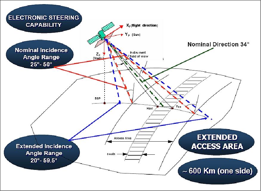
The bus structure material is CFRP (Carbon Fiber Reinforced Plastic) while SVM and PLM consist of aluminum alloys. The interfaces of the SAR antenna, star trackers and gyros are mounted on the CFRP structure for pointing precision and stability (a star tracker is being used as well as a high-quality GPS receiver). The SAR antenna bore sight is pointing with an incidence angle about 38º to the right side of the spacecraft ground track.
• AOCS provides an antenna steering capability of ±2º in yaw as well as for a re-pointing capability to the left side of the ground track.
• ICS (Integrated Control Subsystem): ICS is the controlling system on board the spacecraft for the collection and distribution of information (commands, telemetry, on board data, and timing) and for the supervision of COSMO-SkyMed bus and yayload subsystems.
• TPS (Telecommands Protection System): TPS provides on-board decryption of the telecommands received from ground
• TT&C (Telemetry Tracking & Command): TT&C provides the two-ways S-band communication links between the satellite and the TT&C ground station
• PS (Propulsion Subsystem): Each S/C in the constellation features a RCT (Reaction Control Thruster) system for orbit maintenance. The PS includes six thrusters, arranged in two independently operable branches of three thrusters each, and the propellant and the pressurant, which are stored in a common tank
• TCS (Thermal Control Subsystem): TCS consists of elements that insulate the external surfaces of the satellite, heat pipes and thermal doublers to spread the heat load to be dissipated, radiator panels, and automatic electrical heaters placed under ICS control.
• PDHT (Payload Data Handling and Transmission): PDHT manages all data handling and transmission of the science data generated by the SAR payload. It includes all the necessary interfaces for acquiring telecommands and ancillary data from ICS and for storage, formatting, encryption and ground downlink of the science data from the SAR instrument.
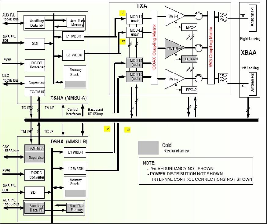
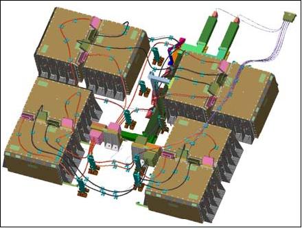
The current TAS-I PDHT reference architecture for medium - large satellites is the one already flying on RADARSAT-2, and on the COSMO SkyMed Constellation (FM1, FM2, FM3). The architecture is depicted in Figure 2. 6)
The following acronyms of Figure 2 are defined:
- TXA (Telemetry X-band transmission Assembly). TXA is composed by two X-Band transmission chain and it includes: a) Differential-QPSK modulators: for each transmission carrier the modulators are dual redundant; b) Coaxial switches matrix to opportunely route modulator output signals towards the power amplifiers; c) HPAs (High Power Amplifiers); d) Output ports filtering and diplexing; e) Waveguide switch matrix to opportunely route signals to be transmitted towards the antennas.
- XBAA (X-Band Antenna Assembly). XBAA includes two deployable isoflux antennas in right and left looking observation configuration, to operate in both attitudes and ensure redundancy.
- DSHA (Data Storage and Handling Assembly). DSHA is composed by two identical Mass Memory Storage Unit (MMSU). The main elements included within each MMSU are: a) Supervisor with On Board Software (OBS). Supervisor is dual-redundant; b) Science Data Interface (SDI); c) Mass Memory Modules stack for storage of SAR payload science data; d) Wideband Data Handler (WBDH) for science data encryption and auxiliary and science data formatting over downlink channels 1 & 2.
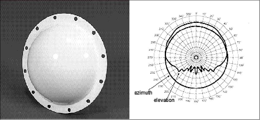
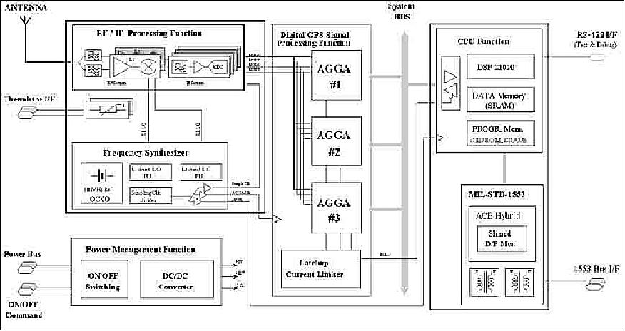
GPS/GNSS receiver: The SSTI (Satellite-to-Satellite Tracking Instrument) is the LAGRANGETM GPS receiver. LAGRANGE is a space-qualified, dual-frequency, GPS receiver designed for navigation purposes. The receiver is built by TAS-I (Thales Alenia Space-Italia), Milan (formerly LABEN SpA). LAGRANGE processes the received GPS and GLONASS signals in both the L1 and L2 frequency bands, allowing compensation of ionospheric delays. A special codeless tracking scheme is implemented to process the encrypted P(Y) signals transmitted in the GPS L2 frequency band.. The instrument is equipped with one hemispherical coverage antenna with (nominal) boresight pointed to the Zenith direction. The receiver uses the AGGA-2a signal processing chip developed by ESA and is currently a payload of several ASI, ESA, ISRO (Indian Satellite Agency) and CONAE (Argentina) missions. 7)
LAGRANGETM onboard COSMO-SkyMed and RADARSAT-2 is designed to process only GPS signals. The on-board orbital determination strategies performed on board for the COSMO-SkyMed and Radarsat-2 missions have successfully reached the required accuracies necessary to guarantee high level SAR products related to Earth imaging.
EPS (Electric Power Subsystem): The mission imaging capability requirements call for very high peak power loads of up to 14 kW. The overall power consumption associated with a specific operating mode profile is:
• Spotlight mode: about 460 to 650 A, max duration of 10 s (single spotlight)
• Stripmap mode (reference to HImage): about 330 to 450 A, max duration of 10 minutes in continuous acquisition.
The solar arrays of the S/C (total area of 18.3 m2, built by Galileo Avionica) provide a minimum power of 4 kW (BOL) and 3.6 kW (EOL, 5 years) using triple-junction solar cells. The EPS (Electrical Power Subsystem) configuration is based on an unregulated bus architecture with a bus voltage in the range from 26 to 37.8 V. The EPS uses the advanced Li-ion technology (Sony US18650 hard carbon lithium ion cells) for its ultra-high energy density. The battery requirements are summarized as follows: 8) 9) 10)
- Battery nominal capacity of 336 Ah
- Maximum depth of discharge of 35%
- Maximum discharge current of 735 A for the SAR peak imaging
- Maximum discharge voltage of 26 V
- Battery total mass of 136 kg
- Minimum battery life of 5 years
- Minimum battery reliability of 0.999 over the mission design life.
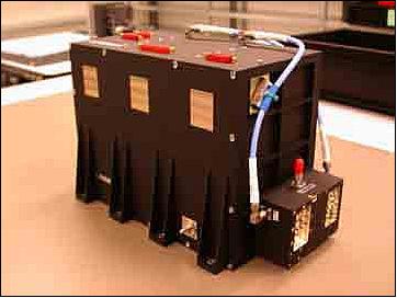
The large Li-ion battery design consists of 2016 cells (a 9S-224P configuration - or a topology of 9 cells in series and 224 strings in parallel), capable of supporting 17.8 kW of peak power demand for some SAR support modes. The battery consists of an assembly of eight identical modules paralleled through two electrical junction boxes and two power bus-bars that connect the junction boxes to the CUS (Current Unit Sensor). The versatility of the S-P topology and the COM DEV design (COM DEV International Ltd., Cambridge, ON, Canada) solution enabled this flexible design to adapt to any power requirement by simply varying tray sizes and the number of modules with minimal impact on design, schedule and cost.
To minimize the magnetic moment of 775 A peak discharges, the two trays in each module are rotated 180º with respect to each other. Since the current in both trays will be of equal value but in opposite directions, this causes the magnetic moment from the top tray to cancel the magnetic moment produced in the bottom tray. The COM DEV battery design represents a technology enabler for the COSMO-SkyMed mission.
The raw power coming from the SA (Solar Array) is conditioned by the PCU (Power Control Unit) using a MPPT (Maximum Power Point Tracking) algorithm. The PCU manages also the charge of the battery, using a control loop algorithm in collaboration with the CUS (Current Unit Sensor), providing the power to the thermal control heaters and drives the on-board pyro devices. The measured power of the SA is > 4.5 kW @ BOL. 11)
• The spotlight mode uses about 13 kW for a maximum duration of 10 s (single spotlight)
• The stripmap mode uses about 7 kW for a maximum duration of 10 minutes as continuous acquisition.
The mass of each spacecraft is about 1700 kg. The design life is 5 years. Each spacecraft in the constellation provides an onboard operational autonomy for a period of about 24 hours.
Launch: The launch of the first COSMO spacecraft in the constellation took place on June 8, 2007 (UTC). The launch was provided by the Boeing Company on a Delta-2 (7420-10 configuration) vehicle from VAFB, CA. This represented the first commercial Delta-2 launch since the formation of the United Launch Alliance (ULA) in December 2006. 12)
Mission | Launch date |
COSMO-SkyMed-1 | June 8, 2007 on a Delta-2 launch vehicle from VAFB, CA; Launch provider: ULA |
COSMO-SkyMed-2 | December 9, 2007 on a Delta-2 launch vehicle of ULA from VAFB, CA, USA |
COSMO-SkyMed-3 | October 25, 2008 on a Delta-2 launch vehicle of ULA from VAFB, CA, USA |
COSMO-SkyMed-4 | November 6, 2010 (UTC) on a Delta-2 launch vehicle of ULA from VAFB, CA, USA |
RF communications: Onboard payload recording is provided with a 300 Gbit solid-state memory. The payload data are compressed and encrypted and downlinked in X-band at 300 Mbit/s. The TT&C function is provided in S-band.
Orbit of Constellation
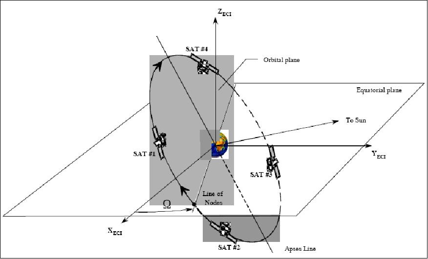
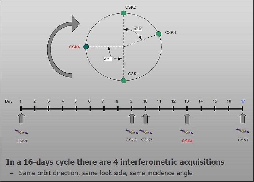
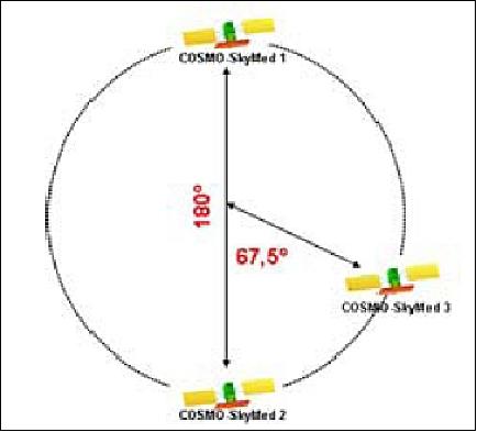
Circular sun-synchronous dawn-dusk orbit, nominal altitude = 619.6 km, inclination = 97.86º, period = 97.1 min, with LTAN (Local Time of Ascending Node) at 6:00 hours (dawn/dust orbit), 14.8125 rev./day (or 14 13/16). All spacecraft of the SAR constellation will be positioned in the same orbital plane with a phasing outlined in Table 2. The nominal repeat cycle is 16 days; however, each single satellite will have a near revisit time of 5 days. 14)
The nominal full constellation achieves a revisit time of a few hours on a global scale. In this context, "revisit" refers to the capability to fly again over a given geographic site and to image the site under different conditions (e.g., with a varying incidence angle).
Constellation maintenance requirements: 15) 16) 17)
• Orbit planes: during nominal operations all satellites of the SAR constellation shall operate on the same orbital plane
• Nominal orbit: dawn-dusk SSO (Sun Synchronous Orbit) with 16 days of orbit cycle in 237 orbit per orbit cycle
• Satellite phasing: during nominal operations, the satellites of the SAR constellation shall be equi-phased on the orbital plane
• Ground track repeatability: the satellites of the SAR constellation shall have a ground track repeatability of better than 1 km
The phasing of the S/C in the orbit plane has been selected to achieve optimum performance in terms of accessibility and revisit time with respect to the number of satellites. Table 3 summarizes the achievable observation performance capabilities of the SAR satellites within the latitudinal coverage of ±20º - 60º.
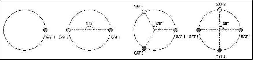
Satellite number | True Anomaly |
1 | 0º |
2 | 0º, 180º |
3 | 0º, 120º, 240º |
4 | 0º, 90º, 180º, 270º |
Potential of bistatic SAR applications: By changing one satellite inclination slightly, to generate a positive drift in the right ascension of the ascending node (RAAN), permits a number of bistatic observations under variable bistatic angle. 18)
Constellation | Right Looking | Left and Right Looking | Comment | ||
Nominal | Extended | Nominal | Extended | ||
1 satellite | 37 to 64 h | 25 to 44 h | 18 to 35 h | 12 to 23 h | Mean revisit time |
<252 h | <120 h | <156 h | <60 h | Max. revisit time | |
38% (24 h) | 55% (24 h) | 67% (24 h) | 85% (24 h) | Access % vs time | |
2 satellites | 19 to 35 h | 13 to 24 h | 9 to 18 h | 6 to 12 h | Mean revisit time |
<108 h | <60 h | <60 H | <36 h | Max. revisit time | |
41% (12 h) | 62% (12 h) | 60% (12 h) | 77% (12 h) | Access % vs time | |
3 satellites | 13 to 24 h | 9 to 16 h | 6 to 12 h | 4 to 8 h | Mean revisit time |
<60 h | <36 h | <36 h | <36 h | Max. revisit time | |
62% (12 h) | 88% (12 h) | 84% (12 h) | 98% (12 h) | Access % vs time | |
4 satellites | 10 to 18 h | 6 to 12 h | 5 to 9 h | 3 to 6 h | Mean revisit time |
<60 h | <24 h | <24 h | <12 h | Max. revisit time | |
80% (12 h) | 99% (12 h) | 97% (12 h) | 100% (12) | Access % vs time | |
Support Mode | Configuration | Comments |
SAR observation side with respect to the nadir ground track | Right-side looking (nominal) | Providing better performance of northern hemisphere coverage |
Duty cycle (estimated on a daily basis) | 75 min of operation in Stripmap or ScanSAR | A duty cycle is needed to overcome the S/C power limitations |
Max. imaging duty cycle (on an orbit basis) | 10 min of continuous operations in Stripmap or ScanSAR |
|
Image acquisition management | On a 24 h basis | Capability of time-tagged commands for SAR-2000 |
PDHT max duty cycle | 20% per orbit |
|
PDHT storage capacity | 300 Gbit onboard memory |
|
PDHT support modes | - Store only | Both in right or left looking |
PDHT downlink rates | - Downlink only | 2 separate links at 150 Mbit/s |
The COSMO-Skymed constellation can be operated in two basic configurations, namely in the "nominal orbital configuration" or in the "interferometric orbital configuration."
• The key requirement of Earth observation for the nominal orbit configuration is "ground track repeatability," needed to keep the subsatellite point within a given accuracy (tolerances of better than ± 1 km) with respect to the nominal ground track. This implies active spacecraft maneuvers for constellation geometry maintenance (compensation for the effects of in-plane and out-of-plane perturbations on the nominal orbit).
• The interferometric tandem configuration is designed to permit observations of 3-D SAR imagery by combining two radar measurements of the same target from slightly different incidence angles. The control requirement for this configuration calls for the maintenance of the interferometric baseline within an accuracy of tens of meters. Hence, in the interferometric configuration, the constellation control involves ground track control (analogous to the nominal configuration) plus the maintenance of the interferometric baseline. This baseline maintenance can be achieved by:
- Tandem-like interferometry (over a period of 1 day). Interferometric observations are achieved within a 24 hour delay.
- The nominal tandem interferometry offers two support modes:
1) The in-plane tandem configuration sets two satellites in the same orbital plane, in close proximity, to obtain the required baseline.
2) Tandem configuration of different orbital planes. This configuration sets the two satellites of the tandem, separated both in phase and in LTAN, with two different orbital planes with slightly different nodes such as to obtain the 'same' ground track.
Mission Status
• June 2018: e-GEOS, an ASI/Telespazio company, provided access for the COSMO-SkyMed data to the commercial world-wide market. In the first 10 years of COSMO-SkyMed activities, e-GEOS delivered more than 117,000 scenes to greater than 760 commercial users, in more than 70 countries world-wide. e-GEOS is also managing the network of COSMO-SkyMed commercial receiving stations (there are now 10 spread all over the world), called CUT (Commercial User Terminal) that allowed customers to downlink COSMO data directly to their antennas for their operational needs. 20)
- As part of its support to the COSMO-SkyMed system and its experience on SAR data and ground operations, e-GEOS has participated in the definition of some of the developments that have been done on the system so far. In particular, e-GEOS has payed and is responsible for the Civilian Routine H12 operations and Submetric civilian mode (Spotlight-2A).
- The COSMO-SkyMed system has a unique characteristic in the world of commercial SAR satellites, as it is a constellation of four satellites placed on the same orbit. The deployment of the four satellites on this orbit has been designed in order to guarantee the highest possible revisit. As a matter of fact, the COSMO-SkyMed system is able to see every point of the Earth at least 2 times every day, one in the morning (about 6 hours local time) and one in the evening (about 18 hours local time).
• December 5, 2017: Italy celebrates the first 10 years of the record-breaking satellite constellation, COSMO-SkyMed. 21) COSMO-SkyMed at the time was the only dual-use (civil/military) Earth observation constellation worldwide. Over its first ten years in operation, it has snapped more than 1 million radar scenes all over the world, monitoring the Earth 24 hours a day, under all weather and visibility conditions. It contributed to national security and supported people struck by natural disasters. It was involved in monitoring deforestation in Amazonia, and providing data and tools for sustainable farming, checking UNESCO sites and monitoring the shrinking of the ice caps in the polar regions, through to monitoring oil spillage in the Gulf of Mexico after the Deepwater Horizon oil platform exploded in 2010.
- Starting in 2018, the second generation of the system would gradually replace the system currently in operation thus improving the efficiency and capacity in sectors that are of paramount importance for security and for protecting our Planet, such as territory observation and sustainable management of its resources, security, and the management of natural events and emergencies, as well as combating the effects of climate change.
• September 2017: The first satellite of the CSK (COSMO-SkyMed) constellation, CSK-1, celebrated its 10 years in orbit (June 2017) and 3 satellites have completed their nominal operational life (5.25 years), but the constellation is still operating and providing data with the required image quality. 22)
- In the next years the operational life of the COSMO-SkyMed system will be guaranteed by a second generation of satellites and an important Ground Segment upgrade, making up the COSMO-SkyMed di Seconda Generazione - or CSG (COSMO-SkyMed Second Generation) system. The CSG constellation will be composed of two additional satellites which, joining those of the first generation, will provide the International Users with new acquisition modes, improved performances, new operative solutions, and enhanced capability to manage and satisfy heterogeneous and complementary dual use requirements. Currently, a specific module of the CSG User Ground Segment (UGS), called Multi-Sensor Interfacing UGS (MSI-UGS), devoted to provide multimission/multi-sensor upstream services to the final users, is in the operational validation phase and it started managing the first generation system from June 2017.
- In 2000, ASI signed a cooperative agreement with CONAE (Comisión Nacional de Actividades Espaciales), Argentina's Space Agency. The agreement was referred to as SIASGE (Sistema Italo Argentino di Satelliti per la Gestione delle Emergenze - Italian/Argentinian satellite system for emergency management). SIASGE is a system of systems composed of four Italian COSMO-SkyMed satellites (X-band SAR) and two Argentinian satellites, SAOCOM (L-band SAR) placed on the same orbital plane. The ASI-CONAE MoU (Memorandum of Understanding) concerning the realization of an integrated X-band / L-band system finalized for emergencies and related applications management was signed in July 2005 (until 2020) with two amendments in 2008 and 2010. Starting from this date, CONAE has been an institutional user of the COSMO-SkyMed system which occupies almost 5% of the monthly production target.
- The launch date of the first satellite SAOCOM is scheduled for 2018. Once entered into its operational phase, the system will be available to be used by both ASI and CONAE. The operational integration of the two systems will provide a significant amount of data (in the bands X, X + L and L), thus opening a vast market of data and products relating to Earth Observation.
• September 2016: One of the most challenging tasks of the COSMO-SkyMed mission is the maintenance of such a complex system. Process and information flows were jointly designed and developed by the Italian Space Agency (ASI), the Italian Ministry of Defence (It-MoD) and Industrial staff in order to continuously guarantee the performances and the availability of the system in a Dual (Civilian/Military) context. 23)
- In order to assure the system functionality, a lifelong system coordination and engineering support have been deployed by the industrial team. This support is guaranteed by maintenance and analysis activities provided by two dedicated teams: an on-site support team deployed in the ground centers (constituted by industrial personnel directly involved in day by day operation and maintenance activities) and a support engineering team located at industrial premises that work in strict conjunction with the Customer to report the end-to-end service performance and efficiency trend during the operative phase. Furthermore, this team is devoted to maintaining and improving the design of the system through the analysis, evaluation and management of the occurred non-conformities. Based on that, it can propose system modifications and enhancements.
- The overall system performances are monthly monitored in order to verify the stability with reference to the committing system requirements. In particular, the system performance is assessed through a dedicated set of effectiveness (Ei) and availability (D) parameters. This allows measuring, in a monthly time frame, if the support system operated in an efficient way. Based on dedicated studies and continuous monitoring of the system it has been possible to identify and propose to Customers potential enhancements to increase the performances with respect to the original specifications. The high flexibility of CSK system allowed configuring new tables to host the configurations of the new spotlight modes without impacting the existing ones.
- The expected performances (resolution and swath) have been reached assuring also the performances related to PSLR (Peak to Sidelobe Ratio) and SSLR (Spurious Sidelobe Ratio) requested for all the standard SAR operative modes of COSMO-SkyMed. The results have been fully in line with those expected and, based on those outcomes, Customers and Industry agreed to make operative the new sensor modes.
- Even though the improvement in the performances could be simplified as an improvement in resolution, it is worth noting that the real improvement is also in radiometry due to the multi-look effect achievable in the azimuth direction (to obtain a pixel square).
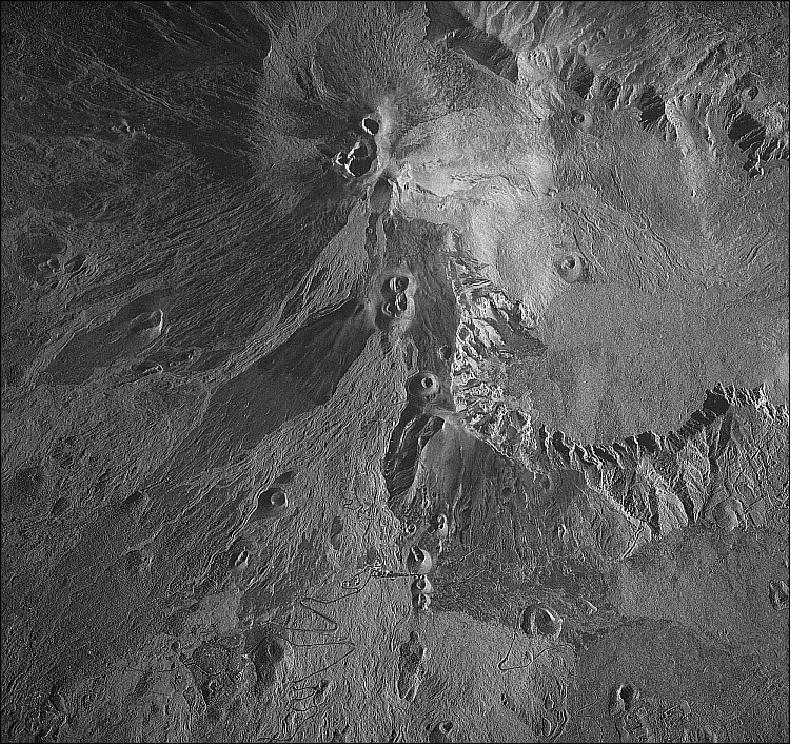
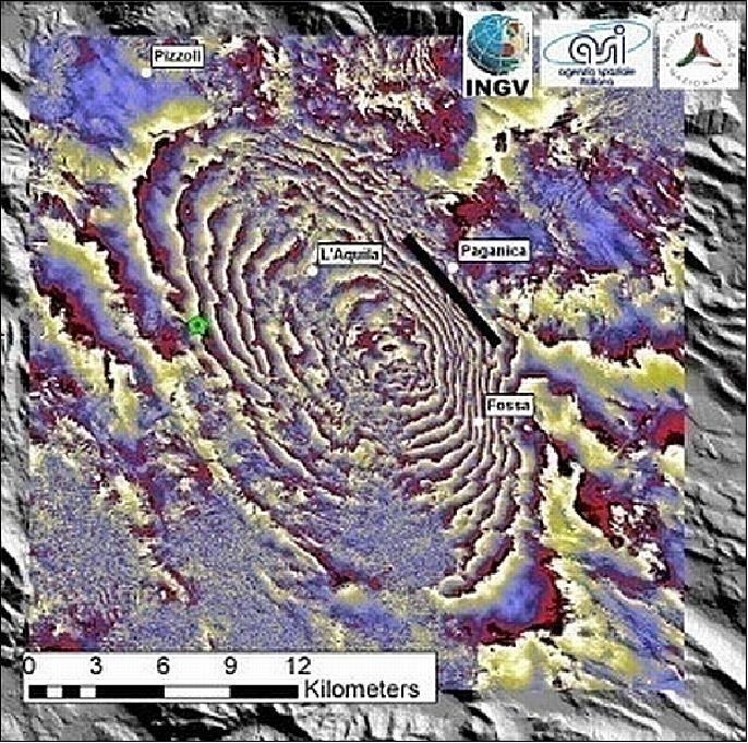
• August 29, 2016: The first satellite images of the areas struck by the earthquake on 24 August were made available by the Italian Space Agency: the "eyes" of the COSMO-SkyMed system, at work right from the first hours after the disastrous earthquake that hit the Apennine areas in central Italy, were set in emergency mode and pointed towards the zones affected by the earthquake that hit at 2.36 hours last week. The data acquired were processed and analysed with the help of the Civil Protection Agency and the INGV to manage the emergency. 24)
• June, 2016: Although all four satellites of the COSMO-SkyMed (CSK) mission were now beyond their design life, the performances of the constellation were fully preserved. This was due to careful monitoring of the entire system to maintain the required performance stability over time with the required efficiency. The continuous maintenance serve of image quality and geolocation performances of each satellite, achieved through the submission of specific acquisitions, confirms that the System is able to guarantee the required performance: 25)
- for all SAR payload imaging modes
- within the time constraints imposed by the mission
- in all system operative modes (Routine, Crisis, Very Urgent)
- sustaining the associated operational loads
- granting the required level of service in terms of availability and efficiency
-ASI developed the CSG (COSMO Seconda Generazione) program with the aim of pursuing the twofold need of ensuring operational continuity to the first generation constellation, while achieving a generational step ahead in terms of functionality and performances so as to further improve the observing power of the existing constellation. The CSG constellation would consist of two satellite SAR constellation, similar to the one on-board of the actual system but with some enhancements: from the performance point of view the quality of the imaging service would be improved, providing the End Users with new enhanced capabilities in terms of higher number of equivalent images and of increased image quality (larger swath and finer spatial and radiometric resolution) with respect to the first generation, along with additional capabilities (e.g. full polarimetric SAR acquisition mode).
Satellite | Launch date | Nominal EOL (End Of Life) | Extended lifetime |
CSK-1 | June 08, 2007 | June 2014 | June 07, 2016 |
CSK-2 | December 09, 2007 | December 2014 | December 08, 2016 |
CSK-3 | October 25, 2008 | October 2015 | October 25, 2016 |
CSK-4 | November 06, 2010 | November 2017 | November 06, 2017 |
• February 25, 2015: The Italian Space Agency (ASI) offered complete data sets from the CSK (COSMO-SkyMed radar satellite Constellation) free of charge. Two separate Open Calls were published, targeted at the national and international scientific community and national private sector SMEs (Small and Medium sized manufacturing Enterprises), start-ups and university spin-offs. A similar initiative took place four years prior, although with different criteria and offered exclusively to the scientific community. 28) 29)
• January 2015: All four COSMO-SkyMed satellites were reported in good health. But the two that entered service in 2007 and 2008 were expected to need replacement in 2017 and 2018 to assure data continuity. A last-minute Italian government allocation of funding for the second-generation COSMO-SkyMed dual-use radar Earth observation program permitted the prime contractor TAS-I (Thales Alenia Space -Italia)to assure the satellites' launches in 2017 and 2018. 30)
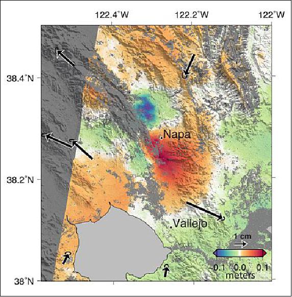
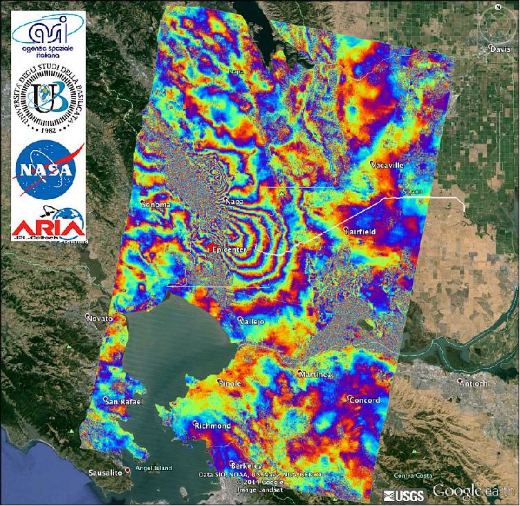
• August 2014: A magnitude 6.0 earthquake struck southern Napa county northeast of San Francisco, CA, on Aug. 24, 2014, causing significant damage in the city of Napa and nearby areas. The earthquake deformed Earth's surface and this deformation was measured by precise analyses of data from nearby Global Positioning System (GPS) tracking stations of the Plate Boundary Observatory (operated by UNAVCO for the National Science Foundation) and the Bay Area Rapid Deformation network (operated by Berkeley Seismological Laboratory). 31)
- NASA/JPL scientists, in collaboration with the Italian Space Agency's (ASI) Center for the Interpretation of Earth Observation Data and the UB (Università degli studi della Basilicata), also analysed radar images from ASI's COSMO-SkyMed satellites to calculate a map of the deformation of Earth's surface caused by the earthquake, as shown in this false-colour map that has been combined with shaded relief topography in gray. The colours indicate the amount of permanent surface movement that occurred almost entirely due to the earthquake, as viewed by the satellite, during the one-month interval between two COSMO-SkyMed images, one before and one after the earthquake.
- The four coplanar satellites, together with a suitable network of ground stations for science data downloading, allow to grant short revisit and response times. The constellation is capable of downloading up to 1800 images/day. During the last 6 years COSMO-SkyMed has been employed to provide "Institutional Awareness", in order to make proper decisions to prevent, respond and manage world-wide crises, to assess damages and supply fundamental information to rescue from catastrophic situations.
• 2013: The COSMO-SkyMed constellation was operating nominally. One important aspect of the mission is the quick provision of imagery for disaster and emergency management due to its daily global coverage capability. 38) In December 2012, the COSMO-SkyMed catalog contained more than 300,000 standard images. ASI provided a certain amount of imagery of selected sites for the COSMO-SkyMed constellation for the study of major geophysical hazards such as earthquakes and volcanic eruptions, in which member organisations of GEO (Group on Earth Observation) and GEOSS (Global system of Earth Observation Systems) were involved for many years.
• June 2012: e-GEOS signed a contract for the setting up of a COSMO-SkyMed Receiving Station in Sodankylä, Finland, to be operated by FMI (Finnish Meteorological Institute) as a part of the Finnish Ministry of Transportation and to become operational before the end of 2012. This agreement provided Finland with COSMO-SkyMed direct reception capabilities over the Baltic and a large part of the Arctic areas to monitor ice formation and movements and Arctic changes. 41)
• January 13, 2012: The companies KSAT (Kongsberg Satellite Services), ConocoPhillips, and e-GEOS (joint venture of ASI and Telespazio for commercial product services) have signed a contract for monitoring ice formation and movement throughout the 2011-12 winter season. The effort will make exclusive use of the unique capabilities of the Italian COSMO-SkyMed constellation of four VHR SAR satellites, owned by the Italian Space Agency (ASI) and exploited commercially by e-GEOS, to provide coverage over the area of interest for the entirety of the season. The frequency and duration of the coverage allowed unprecedented detail on the evolution of sea ice conditions using high-resolution, X-band (9.6 GHz) SAR technology. 43)
- By acquiring coverage for a full season with hundreds of SAR images, it was possible for the first time to thoroughly analyse the patterns of ice formation, the characteristics of the ice under winter conditions, and the progression of the spring melt: how rapidly it occurs and the size and prevailing direction of the ice fragments Ref. 43)

Three different system operative modes are defined:
1) Routine support - the requests of the users pertaining image acquisitions are planned and sent to the constellation once a day
2) Crisis support - the requests of the users pertaining image acquisitions are planned and sent to the constellation twice a day
3) Very urgent. - the requests of the users pertaining image acquisitions are asynchronous, allowing the servicing of an image acquisition request with the minimum possible latency.
- The constellation average daily acquisition capability is 1800 images acquired in a 24 hours window (75 spotlight plus 375 stripmap or 150 ScanSAR for each satellite). Constellation peak daily acquisition capability is 10 minutes of continuous operation in Stripmap or ScanSAR modes or alternatively 20 spotlight images.
• Summer 2011: While product characterisation and calibration measurements started early, the final SAR verification had to wait for the complete verification of all input products (specifically the orbit and attitude data) and the finalisation of the overall SAR system performance and verification. Thus more than a thousand "operational" products of all modes and variants had been used for final verification of basic characteristics like format, saturation degree, scene location and extent. A subset of specific acquisitions over calibration sites were processed to various product variants and analysed with respect to point target responses and radiometry. These measurements confirmed the very excellent COSMO/SkyMed product performance in terms of: Focusing quality and resolution, sensitivity and radiometry 46)
• April 2011, the COSMO-SkyMed constellation was now fully operational and complete with the arrival of the system's fourth satellite in its final orbit position. The satellite was launched on Nov. 6, 2010 (UTC) from the Vandenberg base in California, and came fully on-stream with the transmission of the first images to the ground stations (Ref. 92). The early orbit operations for the fourth COSMO-SkyMed satellite were once again successfully managed by the LEOP (Launch and Early Orbit Phase) team at Telespazio's Fucino Space Center, while the first radar images from COSMO-SkyMed-4 were acquired by the Matera Space Center of ASI.
- The constellation had been used in various applications in the field of risk and emergency management such as: China's 2008 earthquake, Myanmar and Haiti flood, Abruzzo earthquake, ice monitoring (reduction of the glaciers, Wilkins Ice Shelf disintegration), multi-temporal acquisition for agriculture monitoring, interferometry, landslides monitoring, maritime surveillance and security, rapid mapping. The results revealed the strong contribution of the X-band SAR and the importance of satellite constellations getting fast responses and short revisit time. 47)
• December 16, 2010, the project was reporting that COSMO-SkyMed-4 had reached its final orbit and was transmitting its first images. 48)
• November 6, 2010 (UTC), the COSMO-SkyMed constellation was completed with the launch of the COSMO-SkyMed-4 spacecraft from VAFB, CA. This made COSMO-SkyMed the first global Earth observation constellation that had both civil and military applications . The satellite telemetry was acquired on the same day by Telespazio's Fucino Space Center, which is in charge of its operations for the entire duration of the mission.
• Early 2010: The 3-spacecraft constellation was operating nominally. The system was able to provide the products with the required image quality and geolocation performance for all SAR payload imaging modes within the time constraints imposed by the mission in all system operative modes (Routine, Crisis and Very-Urgent), fully sustaining the associated operational loads and granting the required "Quality of Service". 49)

• July 2009: The COSMO-SkyMed-3 spacecraft had completed the commissioning phase was operational. During commissioning the end-to-end system performance had maintained the required stability and the ILS&OPS (Integrated Logistics & Operations) support system had fully demonstrated its efficiency. COSMO-SkyMed-3 is positioned in the so-called "one-day interferometry configuration", allowing the constellation to detect interferometric acquisitions with a de-correlation time equal to one day and to improve the number of data take acquisitions (minimising the acquisition conflicts). 51) 52) 53) 54)
- After the quake, the system began to gather up to 6 images/day, in all possible modes and viewing geometries. During the following month, 3 images/day were acquired, for a total of 100 images. In order to reach this target, all orbital passes, in the ascending and descending nodes, the right- and left- side viewing capabilities, as well as different incidence angles were used (Ref. 51).
• Late 2008: a new company, e-GEOS, was set up for the provision of commercial products and services. e-GEOS is a joint venture between ASI and Telespazio (a Finmeccanica/Thales company). The objective was to bring data from the COSMO-SkyMed satellite constellation to the global market. 56)
• August 1, 2008: The COSMO-SkyMed-1 and -2 spacecraft are fully operational since the commissioning phase ended. The observation data are being used by both civilian (institutional and commercial) and defense users. 58) 59) 60) During the commissioning phase the first two satellites had begun to acquire thousands of images all over the globe, showing the full potential of the system.
• February 2008: The images acquired by the COSMO-SkyMed satellites over the Northern Caspian Sea and the Antarctic region show the great potentiality of the X-band SAR data in ocean and ice applications.
Sensor Complement
SAR-2000 (Synthetic Aperture Radar-2000)
The SAR-2000 instrument was designed and developed by TAS-I (Thales Alenia Space Italia), formerly Alenia Spazio, Rome. SAR-2000 is a multi-mode instrument, a programmable system providing different performance characteristics in terms of swath size, spatial resolution, and polarization configurations. The SAR transmitter/receiver system operates through an electrically steerable multi-beam antenna which concentrates the transmitted energy into narrow beams in the cross-track direction while the characteristics of the transmitted pulses and the echo signal determine the spatial resolution and coverage. 61) 62) 63)
The objectives call for the following design features:
• Very large instantaneous bandwidth
• Electronic beam steering in range and azimuth
• Multi-polarization and full polarimetry support (data takes with selectable polarization and multiple polarizations on the same scene using the ping-pong technique)
• Programmable PRF, pulse width and bandwidth
• Multiple imaging mode support
• Onboard hardware calibration techniques
• Onboard data compression processing techniques (both analog and digital)
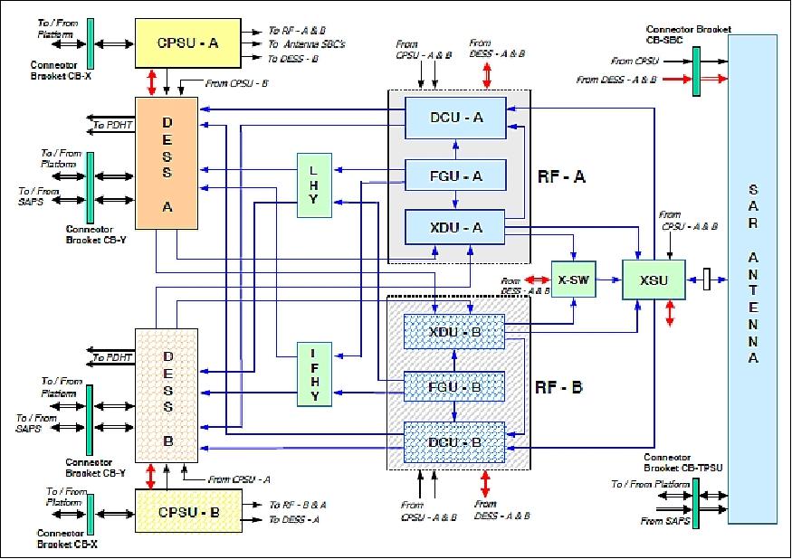
The instrument is composed of two major elements: a phased array antenna subsystem (external equipment), also known as SAA (SAR Active Antenna), and of the central electronics module (internal equipment), also known as SIE (SAR Internal Electronics). The SIE module in turn consists of three parts:
• RFA (Radio Frequency Assembly). RFA has four units: XDU (X-band Driver Unit), XSU (X-band path Switch Unit), DCU (X-band Receiver), and FGU (Frequency Generation Unit).
• DESS (Digital Electronics Subsystem)
• CPSU (Central Power Supply Subsystem)
The SAA is in charge to provide distributed power amplification, beam steering capabilities and low noise reception of echoes through the beam forming functions. The SIE is in charge to provide functions in electronics power supply, signal generation, frequency up-conversion, TX/RX signal routing, frequency down-conversion and data production.
The key design elements of the instruments are: the pulse generation, the band stretching and the up conversion, the active antenna, the deramp on receive for the spotlight mode which replace the first down-conversion scheme of the two stage superheterodyne receiver, the multi-rate A/D conversion with selectable compression algorithm based on BAQ.
The pulse generator is based on baseband (BB) generation followed by SSB modulation: the BB generation is done with a memory read out scheme which allow the generation of the selected waveform by the simple calculation of the samples. Presently chirp waveforms are implemented (with both length and bandwidth programmable in accordance to the specific mode configuration) with the possibility to compensate the effects of both the H/W distortions versus the frequency and the temperature through some predistortion coefficients computed during the on-ground instrument characterization and selectable from a LUT (Look Up Table) according to the specific programmed configuration.
The up-converter is based on a first stage conversion (from chirp carrier to 2400 MHz) followed by a x4 frequency multiplication; the results of such a scheme if twofold: 1) it implements the up conversion to X-band (9600 MHz) carrier frequency; 2) it performs a bandwidth stretching to achieve the resolution requirements in spotlight mode. On the opposite site, that architecture imposed a very tight control on the image rejection and spurious level suppression to avoid any reduction in signal dynamic after deramping.
The Rx chain is based on a two stage superheterodyne scheme where the first stage is replaced by a deramping function for the spotlight mode only. The IF stage implements four bandpass filters to be selected according to the specific operation mode and configuration. The last stage is the I-Q demodulator that operates directly at 2400 MHz IF. The digital section is based on a programmable multi-rate A/D converter followed by the pre-processor (decimator) and the Block Adaptive Quantizer (8:4, 8:3, 8:2, and 8:1 processing schemes and the possibility to by-pass the compression). The data are formatted in CCSDS like standard packets for the transmission on a high speed link (HotLink) with the nominal data data rate of 600 Mbit/s.
Antenna: The SA-2000 X-band antenna subsystem, also referred to as SAA (SAR Antenna Assembly), is a large deployable planar phased array operating in dual linear polarization, able to generate and to steer T/R beams, capable of assuming many different shapes along the antenna elevation plane. Moreover the antenna has in-orbit calibration features and the possibility to upload newly designed beams. 64) 65) 66)
The mission requirements call for the following features:
• Beam steering on the two main antenna planes
• Elevation beam shaping according to different masks (up to 68) required by the instrument to implement the different operating modes
• High speed selection of the two linear polarizations
• High peak power generated inside the antenna
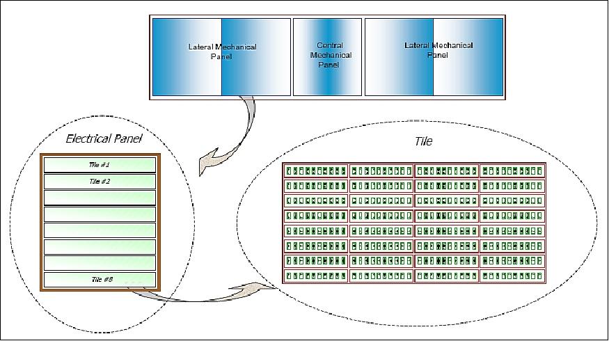
The SAA antenna has dimensions of 5.7 m x 1.4 m (elevation steering range of ±15º), consisting of 40 identical tiles arranged in five identical electrical configurations (5 horizontal electrical panels of 8 vertical tiles each). Each tile consists of:
• 32 T/R (Transmit/Receive) modules, grouped in 4 electronic front ends (EFE), to amplify and control the RF signal
• 2 DC/DC tile power supply units (TPSU) to supply the required energy to the modules
• The intermediate digital controller (SBC) to control and to compensate the modules settings
• A true time delay line, to stabilize the beam pointing in the frequency band and to amplify both the Tx and Rx RF signals.
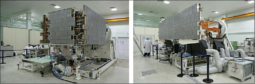
Within a tile there are all functions needed for beam forming and reception. Each tile is a self-consistent active antenna element including all functional support (thermal, RF, digital and power). The antenna has a total of 1280 T/R modules.
A photo of the antenna panels with the 40 tiles is shown in Figure 25. The tiles are arranged into a double staggered grid in order to spread the grating lobes energy and reduce their peak level. The tiles are mounted on an aluminum panel frame, which supports also the mechanisms for hold down and deployment and the antenna harness.
Two beam forming networks (one for the RF Tx / Rx distribution and one for calibration purposes) are mounted on the tiles supporting frames of the three panels. The digital control of the antenna is achieved by five 1553 digital busses, one for each column of 8 tiles.
The following operational acquisition modes are supported: Stripmap, ScanSAR, and Spotlight. The SAR data localization accuracy is 25 m without GCP (Ground Control Point).
The single orbital plane constellation offers a number of interferometric applications/features such as:
• A full interferometric accessibility (i.e. a double acquisition of all sites with the same incidence angle within the 16 day orbit repeat cycle
• No degradation of the mean revisit time with respect to the performances achievable with the same number of satellites
• A fixed time period of one day between two interferometric acquisitions.
SAR product examples: Multidate basic products, stereo pairs for radargrammetry, interferograms (for DEM and DTM) or differential interferogram, coherence products, etc.
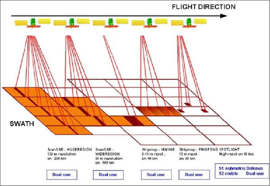
Although the swath width of the SAR instrument is between 10-200 km (depending on support mode), a total FOR (Field of Regard) of 1300 km in the cross-track direction is available for event monitoring applications (for revisit times of < 12 hours for the full constellation).
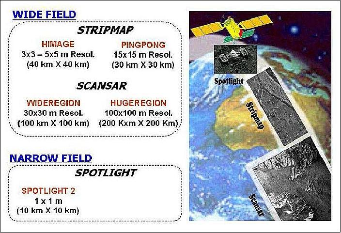
Operational modes with one polarization selectable among HH, VV, HV, or VH | |
Spotlight (also referred to as "Frame") | Spatial resolution: ≤ 1 m |
HIMAGE (Stripmap) | Spatial resolution: 3-15 m |
WideRegion (ScanSAR) | Spatial resolution: 30 m |
HugeRegion (ScanSAR) | Spatial resolution: 100 m |
Operational modes with two polarizations selectable among HH, VV, HV, or VH | |
Ping Pong (Stripmap) | Spatial resolution: 15 m |
SAR Instrument Calibration
The required radiometric stability is achieved through the compensation of instrument fluctuations. This is done by in-flight verification of the instrument against the pre-flight instrument characterization. 68) 69)
The critical part of the instrument is SAA. The instrument stability is based on two mechanisms: a) the compensation of the TRM (T/R Module) variations versus temperature, and b) the internal calibration. The compensation of the TRM variation vs temperature is implemented by the tile control units (SBC) in the background of the instrument operation. The TRM compensation is based on the complete characterization of each module during the ground test. The characterization data are being stored in the SBC look-up table to select the TRM settings according to those commanded and the actual temperature value of the specific TRM. The refresh rate of the TRM setting is equal to PRF (Pulse Repetition Frequency).
The internal calibration subsystem of the SAR instrument monitors all critical parts of the radar (i.e. the passive linear arrays are outside the loops) in a special calibration mode (TRCAL). The internal calibration is performed by sending dedicated pulses along the signal path, according to the specific system timeline. Three different calibration pulses are used:
• CalTx is used to perform the calibration of the transmit path (V and H polarizations can be selected)
• CalRx is used to perform the calibration of the receiving path.
• Short Cal is used to perform short calibrations at the electronics level.
The relative radiometric accuracy depends mainly on the compensation of the antenna pattern. The in-flight determination of the actual patterns would lead to an increase of the commissioning period without the availability of a reliable antenna model.
The absolute radiometric accuracy depends mainly on the estimation and compensation of the radiometric bias. This activity is done with the acquisition of standard target imagery or known RCS (Radar Cross Section).
Split SAR Antenna Design for Multi-Beam Operational Modes
In the time frame 2004/5, the SAR antenna design was modified into a multiple sub-aperture configuration. This improved "split-antenna design" provides a number of extra support mode and performance capabilities such as: 70) 71) 72)
• Clutter cancellation and detection of slowly moving ground targets for surveillance mode support. This feature is referred to as MTI (Moving Target Indication). MTI systems employ the STAP (Space-Time Adaptive Processing) technique to cancel the background clutter. STAP offers a means of detecting targets that compete with clutter located within the skirts of the mainlobe.
• Sea current/wave monitoring by along-track SAR interferometry (ATI) using two independent receiving channels with the largest possible horizontal along-track baseline
• Exact positioning and imaging of moving targets in the high-resolution SAR imagery; this feature is also referred to as "Reloc" (Relocation of moving targets in high resolution SAR images)
• Increased monitoring capabilities by collecting for instance fully polarimetric imagery; this feature is also referred to as "MultiPol" (Multi-Polarization imagery).
The phased array antenna design, composed of 5 horizontal electrical panels of 8 vertical tiles each - is being split up into five channels by acting at the level of electrical panels, and into up to 40 sub-apertures, acting at the level of tiles. This operational scenario does not require any modifications of the tiles and their T/R modules (this means limited impact on original antenna).
The new multi-beam antenna configuration considers all symmetric configurations obtained by splitting the whole aperture into 2, 3, 4, 5 horizontal subapertures and into 2 vertical subapertures. These configuration instances are described in Table 8, where the value `0/1' specifies whether a given panel is "not used/used" in a specific sub-array, the symbol `+' splits up sub-arrays whose outputs are used simultaneously, and panels represented in bold are shared by adjacent sub-arrays.
• The STRx (Standard Receive) configuration corresponds to the actual single channel antenna design
• The SPAN No (Split Antenna) configurations refer to the horizontal partitions of the array into multiple (No) sub-apertures
• The SPAN 2V (Vertical Split Antenna) configuration corresponds to a vertical partition of the array into 2 subapertures
• The ALRx No (Alternating Receiver) configurations are based on an alternate reception with a leading and a trailing subaperture that uses a certain number (No) of external antenna panels.
Configuration name | Configuration | Multi-beam applications | |||
MTI | ATI | MultiPol | Reloc | ||
STRx (Standard Receive) | 11111 | o |
|
|
|
SPAN 2a (Split Antenna) | 1+000+1 | o | o |
| o |
SPAN 2b | 11+0+11 | o | o | o | o |
SPAN 2c | 111+111 | o | o |
| o |
SPAN 3a | 1+0+1+0+1 | o | o |
| o |
SPAN 3b | 11+1+11 | o |
|
|
|
SPAN 3c | 1+111+1 | o |
|
|
|
SPAN 3d | 111+111+111 | o | o |
| o |
SPAN 4 | 11+11+11+11 | o | o |
| o |
SPAN 5 | 1+1+1+1+1 | o | o |
| o |
SPAN 2V (Vertical Spilt Antenna) | 11111+11111 |
|
| o |
|
ALRx 1 (Alternating Receive) | 10000 | o | o |
|
|
ALRx 2 | 11000 | o | o |
|
|
ALRx 3 | 11100 | o | o |
|
|
New operational modes have been conceived for the multi-beam applications, of three types:
1) Wide Area Surveillance (WAS) modes (based on a ScanSAR acquisition mode) optimized to obtain large swath width with a reduced ground resolution (conceived for MTI and experimental for ATI)
2) Continuous Imaging (IMA) modes with intermediate values of swath width and resolution corresponding to a StripMap acquisition mode
3) High Resolution Imaging (HRI) modes (based on a SpotLight acquisition mode) optimized to obtain high resolution on reduced dimension swath (conceived for MultiPol and Reloc, and experimental for MTI due to the very high value of the signal bandwidth).
The design of the multi-beam operational modes included the specification of the product geometric characteristics (swath width, resolution, number of looks) and the design of appropriate sets of beams (PRF + off-nadir angle + antenna beam-width + pulse width) that assures the coverage of the ground access area (incidence angles from 25º to 57º) without range ambiguities and avoiding ALE (Altitude Line Echo). One of the main limitations in the design of the new multi-beam modes is the required data rate, which is mainly affected by:
• The number of receiving channels
• The range resolution (namely the chirp bandwidth)
• The oversampling factor (OVS) of the range bandwidth (specifically, for MTI an higher value has to be used in order to perform the digital equalization of the receiving channel required to obtain an effective clutter cancellation
• The number of bits used to encode the samples (I+Q) with reference to the BAQ (Block Adaptive Quantizer) compression level acceptable for each Multi-Beam application.
A trade-off between increase of data rate and performance in the multi-beam techniques suggests to optimize the operational modes for two different antenna configurations:
1) A "Reduced Solution" (2 Rx channels) usable either for SPAN 2b or for STRX + 1 auxiliary signal for ECCM (Electronic Counter Counter Measure) techniques
2) A "Complete Solution" (5 receiving channels), usable for: (a) SPAN 5 (or SPAN 4 through digital beamforming), (b) SPAN 2b/SPAN 3b+3/2 auxiliary signals for ECCM, or STRX + 4 auxiliary signals for ECCM.
Ops mode | Swath in range (km) | Range resolution (m) | Antenna configuration | Tau (µs) | Bit (I+Q) | OVS | Data rate (Mbit/s) |
MT2-WAS | 75-100 | 11.6 | SPAN 2b | 40 | 8+8 | 2 | ≤ 1200 |
AT12-WAS | 75-100 | 2.7 | SPAN 2b | 40 | 3+3 | 1.25 | ≤ 1200 |
MT2-IMA | 25-40 | 11.6 | SPAN 2b | 40 | 8+8 | 2 | ≤ 1200 |
AT12-IMA |
|
|
|
|
|
|
|
MPol-HRI | 5-10 | 0.89 | SPAN 2b | 80 | 3+3 | 1.2 | ≤ 1000 |
Ops mode | Swath in range (km) | Range resolution (m) | Antenna configuration | Tau (µs) | Bit (I+Q) | OVS | Data rate (Mbit/s) |
MT5-WAS | 75-100 | 14.4 | SPAN 5 | 40 | 8+8 | 2 | ≤ 2400 |
ATI4-WAS | 75-100 | 2.7 | SPAN 4 | 40 | 3+3 | 1.25 | ≤ 2400 |
MT5-IMA | 25-40 | 14.4 | SPAN 5 | 40 | 8+8 | 2 | ≤ 2400 |
ATI4-IMA | 25-40 | 2.7 | SPAN 4 | 40 | 3+3 | 1.25 | ≤ 2400 |
RL4-IMA | 25-40 | 2.7 | SPAN 4 | 40 | 3+3 | 1.25 | ≤ 2400 |
MT5-HRI | 5-10 | 6 | SPAN 5 | 80 | 8+8 | 2.4 | ≤ 2000 |
RL4-HRI | 5-10 | 0.89 | SPAN 2b | 80 | 3+3 | 1.2 | ≤ 2000 |
SABRINA (System for Advanced Bistatic and Radar Interferometric Applications)
In the framework of COSMO-SkyMed follow-on activities, ASI plans to design, develop and operate a bistatic and interferometric mission, SABRINA. The SABRINA mission concept uses a passive satellite, namely BISSAT (Bistatic and Interferometric SAR Satellite), which is to co-orbit in close formation with one of the COSMO-SkyMed constellation spacecraft. The overall objectives of the SABRINA mission are: 73) 74) 75) 76)
• To conduct experiments involving a bistatic and interferometric configuration - using two antennas operating simultaneously
• To investigate new applications by complementing monostatic SAR data with multi-angle, multi-baseline bistatic-interferometric data, to add value to the data products and to attain further objectives of ASI's National Space Plan (PSN)
• To operate a formation in multiple configurations, involving such functions as: orbit control and navigation, stable attitude pointing, signal synchronization, baseline measurement and control, and switching from interferometric to bistatic configurations.
The following scientific applications and products are expected from the SABRINA mission:
- Characterization of bistatic scattering and the study of its effects on imagery. Bistatic measurements help to discriminate the physical scattering mechanisms inherent to surface clutter; in particular, they are useful when the monostatic radar cross section of a terrain is rather weak. The studies involve a spectrum of items: effects of baseline decorrelation, multi-angle observation on data classification, polarimetric analysis of bistatic data, differences between monostatic and bistatic scattering of sea surfaces driven by wind, etc.
- Development of techniques for obtaining digital elevation, slope and velocity maps (radargrammetry, multi-angle Doppler analysis, bistatic scattering from rough surfaces for slope determination, etc.)
- Development of new procedures for bistatic SAR data processing (focusing, motion compensation, effects of bistatic geometry, use of active and passive calibrators, etc.).
As of 2006, SABRINA and BISSAT are in their study phase at ASI.
Background on ASI-CNES Agreements (International Cooperations)
Since 1997 CNES (France) is studying the use of smaller satellites (a medium spacecraft size of about 900 kg instead of 3 tons as for the SPOT-5 S/C), resulting in the "3S" platform concept (Small Satellite System) standing for "Suite de Systeme SPOT" or for "SPOT Successor System." The focus is on cost reduction, technological innovation, user services, and performance upgrades for a new generation of optical imaging satellites, referred to as Pleiades. 77) 78) 79) 80) 81)
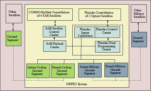
• On Jan. 29, 2001, an intergovernmental agreement (memorandum of understanding) was signed during the Turin meeting between Italy (Guiliano Amato) and France (Lionel Jospin). The objective of this agreement, referred to as ORFEO (Optical and Radar Federated Earth Observation), is the cooperation of France and Italy on a "dual high-resolution Earth observation system," comprising a two-satellite constellation in the optical region under the leadership of France, and a four-satellite constellation under Italian leadership in the microwave region of the spectrum (initially X-band SAR). The intent of this agreement is to provide a long-term perspective on a number of high-quality data products and services on the commercial market for a wide range of applications in the fields of cartography, agriculture, forestry, hydrology, and geological prospecting. The dual service concept is seen in the data requirements of the defense and civilian communities with an option of a daily revisit capability. The agreement calls for funding and development of the space segment by each country and a common sharing of the ground segment. 82) 83) 84)
• In 2000, ASI signed a cooperative agreement with CONAE (Comisión Nacional de Actividades Espaciales), Argentina's Space Agency, Buenos Aires. The agreement, referred to as SIASGE (Sistema Italo Argentino de Satélites para la Gestión de Emergencias - Italian/Argentinian satellite system for emergency management), has been signed under which the satellites in the Argentine SAOCom (SAR Observation & Communications Satellite) system will operate jointly with the Italian COSMO-SkyMed constellation in X-band to provide frequent information relevant for emergency management. This approach of a two SAOCom and a four COSMO-SkyMed spacecraft configuration offers an effective means of a twice-daily coverage capability. By joining forces, both agencies will be able to generate SAR products in X-band and in L-band for their customers. - SAOCom is the CONAE constellation of 2 L-band SAR satellites. A launch of SAOCom-1A is expected in 2015. Once entered into its operational phase, the system will be available for use by both agencies, ASI and CONAE.
In this framework the Italian and French Governments started a cooperation with the goal of Earth observation for dual-use applications (military and civil) with SAR and optical instruments based on the on-going COSMO-SkyMed and Pleiades small satellite programs, respectively. This dual-use scenario calls for missions that offer advanced observation capabilities in several modes of operation, permitting to meet the objectives of the military and civil communities at the same time. The development of innovative and complementary instrumentation in the radar field (e.g., multi-mode and flexible-support SAR's offering high-resolution data) and in the optical field (e. g., hyperspectral sensor with capabilities of variable spatial resolutions as well as high detection sensitivities in the visible and infrared spectral regions) are major objectives of the programs.
The earlier memorandum of understanding was followed by a Memorandum of Agreement (MoA), for the ORFEO system definition step, between the French space agency (CNES) and the Italian space agency (ASI). The MoA was signed on June 22, 2002 at the Paris Air Show.
The COSMO-SkyMed / Pleiades space segment is based on a constellation of small satellites combined with a fast data reception capability. The provision of data on an operational basis (of continuity and quality) is essential for the system.
The constellation will be deployed in two orbital planes, one orbit plane for the SAR satellites and one orbit plane for the optical satellites. This permits a) the SAR satellites to collect the maximum solar radiation for S/C power demands in sun-synchronous dawn-dust orbits, and b) the optical satellites to operate under optimal illumination conditions in a sun-synchronous near noon orbit.
• In 2009 an intergovernmental agreement MOU (Memorandum of Understanding) was signed between ASI and JAXA concerning the feasibility study and joint research activities for the mutual cooperation in the satellite disaster monitoring. In this framework a cooperative project was implemented for:
- Feasibility study and demonstration on improvement of observation frequency and coordination during emergencies, using COSMO-SkyMed (X-band), ALOS (L-band), COSMO-SkyMed 2nd generation (X- band) and ALOS-2 (L-band) satellites.
- Cooperation in joint SAR research activities related to disaster monitoring.
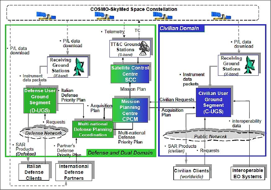
Ground Segment
The COSMO-SkyMed / Pleiades ground segment provides all the infrastructures needed to support the mission in a dual-use scenario (functions/operations in terms of constellation control and global data management). Telespazio was the prime contractor for the development and construction of the civil and military ground segment, and now controls the constellation's in-orbit operations. e-GEOS S.p.A., a joint venture between the Italian Space Agency (20%) and Telespazio (80%) is responsible for the acquisition and processing of COSMO-SkyMed data, and sells it on the international market. e-GEOS is also the European distributor of GeoEye-1, IKONOS, QuickBird, WorldView-1/2, EROS-A/B, and Radarsat-1/2 satellite data (Ref. 57).
The various elements of the COSMO-SkyMed ground segment are:
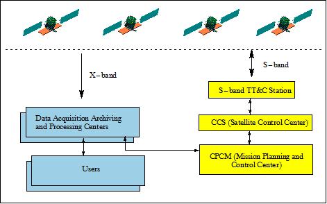
• CPCM (Centro Planificazione e Controllo Missione - Mission Planning and Control Center). Coordination of on-board and ground activities, mission planning, and resource allocation.
• CCS (Centro Controllo Satelliti - Satellite Control Center). Provides the monitor and control function of the constellation including flight dynamics. The CPCM and CCS functions are located at Fucino, Italy.
• TT&C stations. Primary service link between the space and ground segments (dedicated communications network).
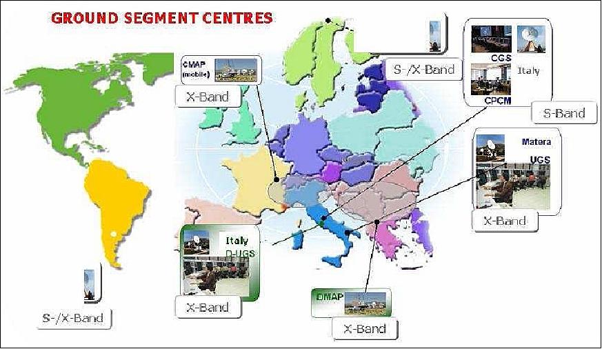
• CREDO (Centro Ricezione ed Elaborazione Dati Operativi). CREDO operates X-band stations for high-rate data acquisition and provides data archiving and processing. To the user side there is a two-fold function:
- As a civil support facility which handles civil user requests: The UGS (User Ground Segment) function is located in Matera, Italy.
- As a military support facility to handle the military service needs: The UGS for military applications is located in Pratica di Mare, Italy.
- In addition there are mobile stations supporting UGS.
ASI is developing an entity dedicated to EO Data Management in the framework of ASI Multimission National Center, devoted to realize applications and tools image data mining oriented. 85) 86)
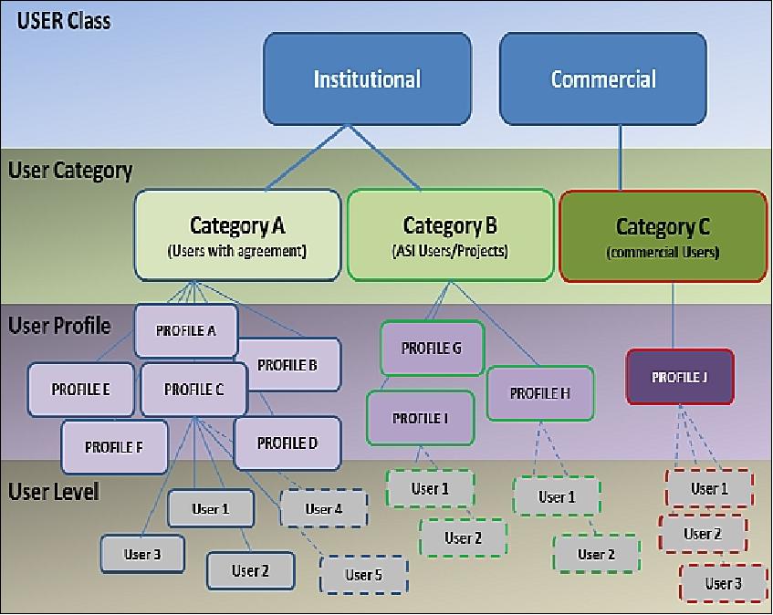
Data Policy and Data Access: Due to the dual use feature of the system, COSMOSkyMed data access is regulated by means of an appropriate and well-defined data policy. Users are classified mainly in two separate domain: Civilian domain and Defence domain. In the Civilian domain users can be: 87)
• institutional users
• commercial users.
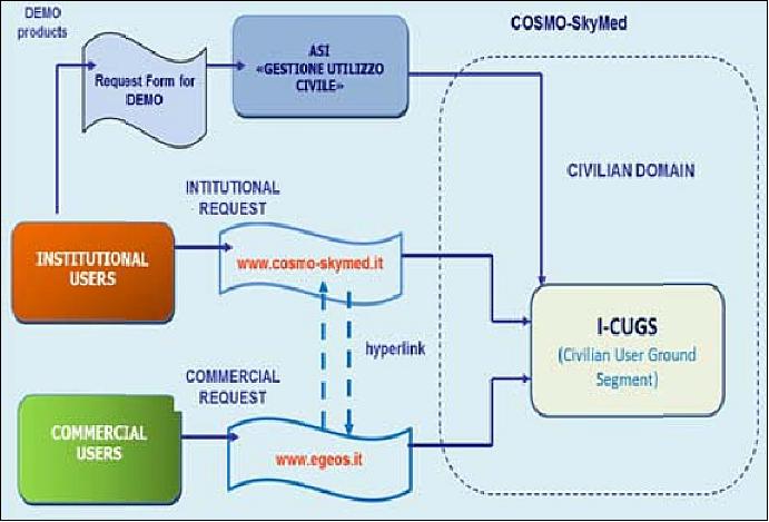
Institutional users are international partners, national and international Administrations, Agencies, Ministries, Universities, Research Centres, etc. ASI manages and coordinates institutional and scientific users allowing the utilization of the service for acquisitions and products ordering by mean of the COSMO-SkyMED website, whereas the commercial users can access the system through the commercial provider e-GEOS, an ASI-Telespazio Company. In the first case, specific agreements are signed and shared among the partners; similarly, commercial users regulate their relationship with the commercial provider by means of commercial contracts.
In order to define the access rules to the COSMO-SkyMed system, it is necessary to determine the characteristics of the User, which determine the access rights and the characteristics of the service that the user may require. The User classification levels are the following:
• USER CLASS (classification according to the Data Policy): institutional or commercial.
• USER CATEGORY (classification according to the configuration defined in the agreement). There are 3 categories: A (users with agreement); B (ASI users, including specific projects approved by ASI); C (commercial users).
• USER PROFILE (classification defined at System / User Ground Segment).
IEM (Interoperability, Expandability and Multi-sensoriality) Capability
One of the major problems the EO user community has to face with is the high number of existing/planned spread EO facilities, each providing different specific, regional or thematic functions (e.g. near real time data production and distribution, off-line archive, added value services, etc.) 88) and Ref. 5).
Some international initiatives, such as GMES (Global Monitoring for Environment and Security), GEOSS (Global Earth Observation System of Systems), and, for Defense, MUSIS (Multinational Space-based Imaging System), aim at finding a viable way to provide cost-effective solutions for future EO systems, granting users with simple access to Multi-Mission/ Multi-Sensor (MM/MS) capabilities and streamlined operations.
The COSMO-SkyMed System architecture provides a key mechanisms for implementing the future EO systems MM/MS capabilities by having been envisaged, from the elder design phases, as a versatile system able to easily and cost effectively expand its architecture toward a set of "partner-mission" (up to 5 civilian and up to 5 defence partners) so to cover a larger variety of utilization needs (e.g. optical, hyperspectral or other radar bands).
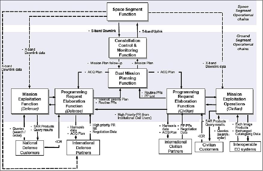
The IEM concepts and their implementation into the COSMO-SkyMed ground segment.
• Interoperability: This is the capability of exchanging data and information with external heterogeneous systems according to predefined agreed modalities and standards, and irrespective of internal design of the cooperating parts.
The COSMO-SkyMed architecture implements standard Catalogue Interoperability Protocol based on CEOS (Committee on Earth Observation Satellites) guidelines, through which it provides access to a variety of EO systems worldwide, to cover the observation needs of the largest number and typologies of Users, mainly for civilian institutional, commercial, and scientific purposes.
• Expandability: This is the ability of an architecture to embody mission-specific components "imported" from partner's EO system, according to a well defined set of standardized interfaces and protocols.
The COSMO-SkyMed architecture is designed to be able to integrate PFIs (Partner's Furnished Items) from different partner systems, such as: (1) Acquisition Chain, (2) Processing Chain, and (3) Programming Chain, to locally achieve multi-mission and multi-sensor capabilities. - Reciprocally, COSMO-SkyMed mission-specific components can be configured as PFI to be exported towards a partner's EO system.
• Multi-sensoriality: This is the system ability to request, process, and manage data related to different observation sensors. Multi-sensoriality concerns a number of end-to-end functional chains, in turn:
- Mission Programming Chain, including depositing, analysis, harmonization of Programming Requests for acquisition from multiple sensors, up to the scheduling of the related image data takes
- Image Chain, to process data generated from different sensors, then to extract and to correlate the imaging features
- User Service Chain providing End-Users with the capability of searching and ordering products from different sensors, as well as multi-sensor (e.g. co-registration) products.
The multi-sensoriality feature does not necessarily imply the co-location of all architectural elements related to different sensor data on the same UGS site. For example, a multisensor 'User Service Chain' can be implemented through standard 'Catalog Interoperability' established among EO systems "federated" to provide integrated system services to the user community.
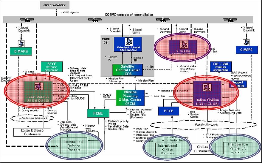
The growth capabilities are important flexibility elements for COSMO-SkyMed product and data distribution to external (institutional, defense or commercial) "clients". In fact, COSMO-SkyMed "clients" can not only get products acquired from main COSMO-SkyMed centers, but also build-up their own user center, in order to perform autonomously and locally programming, acquisition and processing activities. In this context, two significant examples of real COSMO-SkyMed expansion are the following:
1) French Defense User Ground Segment (F-DUGS) – expansion "by-partner"
2) Portable/Commercial User Terminals (TUP) – expansion "by-terminal"
In addition, COSMO-SkyMed is also involved in further on-going cooperation programs, namely:
• SIASGE: Italian-Argentine cooperation program, in which COSMO-SkyMed will: a) provide a COSMO-SkyMed partner user center to CONAE; and b) embody the SAOCOM L-band processors PFIs within the COSMO-SkyMed civilian UGS (User Ground Segment).
• MUSIS (Multinational Space-based Imaging System): interoperability between COSMO-SkyMed and other European Defense Earth Observation systems.
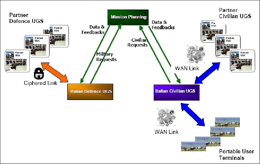
F-DUGS is an example of expansion "by-partner" of COSMO-SkyMed System, which means an additional complete partner UGS, developed for providing French defense users with access capability towards COSMO-SkyMed, in the frame of the ORFEO cooperation program.
The F-DUGS center is located in France and is scheduled to become operational in 2010. From an architectural point of view, F-DUGS is an additional instance within COSMO-SkyMed Defense user centers, equipped with all necessary technical means and solutions for guaranteeing security, integrity and confidentiality constraints, and provides end users with capabilities for:
• Request programming and pre-feasibility analysis, including request harmonization with other defense partners
• Satellite data acquisition, by local antenna or by means of COSMO-SkyMed external stations
• Data processing and distribution
• Archiving and cataloguing of all generated products and related auxiliary data.
The F-DUGS center is autonomously operated by French personnel, and it is operatively integrated with COSMO-SkyMed system by means of a well defined set of interfaces and processes, which allows the center to be informed on system chronologies changes, on relevant on-board activities.
FMCS (System Monitoring and Coordination Function)
A dedicated FMCS system has been designed and implemented as part of the end-to-end system to monitor performances, operations and logistics capabilities, and therefore to optimize the associated operational/supporting cost. The COSMO-SkyMed FMCS system specifically allows: (Ref. 49)
• System performance monitoring
• Support system efficiency monitoring
FMCS has been specifically designed and developed as a set of machines, tools, human operators and procedures customized onto the COSMO-SkyMed system to be coordinated and managed. The multi-mission FMCS can be seen on the one hand as an information retrieval and provision service by which its users can retrieve all necessary data related to the EO system behavior. On the other hand, it can be seen as an integrated "overall procedure" involving machines, information systems and human decision boards, at the various levels of the system hierarchy, all cooperating through schedule-driven timelines and rules to systematically monitor the global system behavior and adaptively decide about the best way to operate it.
Basic objectives to be pursued by FMCS function are:
- System management
- Operative life coordination
- Support system efficiency evaluation
- System technical balances evaluation
- Performance degradations and system/subsystem failures temporal trends retrieval
- Other functions related to the dual-use of COSMO-SkyMed.
COSMO-SkyMed Background Mission
Since the launch of the first satellite in 2007 the exploitation of the system kept growing steadily. Initially, the COSMO-SkyMed exploitation was mostly "on demand", on the basis of specific user requests and signed agreements. When the constellation was fully deployed and became fully-operational, it was decided to exploit the wide imaging and processing capacity offered by of the system implementing a well-defined Background Mission allowing to maximize the system exploitation during the operational lifetime of the constellation and to build up consistent data sets taking into account the overall mission objectives. The idea is to generate a "historical image archive" or "strategic data set" to be used when necessary in the future, for both, institutional and commercial use. 92)
Guidelines and General Requirements
A low priority background acquisition strategy needs to be systematic and to guarantee a global coverage and/or a significant coverage, allowing to minimize conflicts with existing user requests. The acquisition plan has to be kept as simple as possible in order to be exploited with low priority modality. A systematic background mission allows to obtain regular, repetitive and comparable acquisitions: an essential aspect to build a historical data series and to provide for continuity of the observations. The global coverage allows to satisfy a wide user community for both scientific and commercial needs, to guarantee a more effective monitoring of the Earth's resources.
Nevertheless, the global coverage may not be the best strategy of coverage, when considering the high degree of complexity of a dual use system, which might limit the system flexibility.
The areas of interest for the COSMO-SkyMed Background Mission (part of which is shown in Table 11) were selected by collecting the expression of interest related to specific sites and topics coming from the scientific and institutional community and taking into account possible customers' future needs. The main area selection criteria are:
- population density (populated areas worldwide, large cities, cities, capital cities)
- economic and strategic relevance (oil and gas sites, UNESCO sites, dams, main railroads, etc)
- sensible areas (active volcanic sites worldwide, seismic areas worldwide, areas subject to subsidence phenomena, glaciers).
Topology | Frequency of observation | Number of Sites |
Cities | 4/16 days | 736 |
Extended cities (depending on the number of standard frames to cover the total area) | From 1/16 days | 226 |
UNESCO sites | 4/16 days | 264 |
Volcanic regions | 4/16 days | 162 |
Infrastructures | 4/16 days | 13 |
Oil & gas exploration | 4/16 days | 12 |
Subsidence | 4/16 days | 15 |
Acquisition geometry | Polarization | Acquisition mode | Revisit time | Image mode |
Constant and lying in the range 22º-37º (incidence angle) | HH | Right (nominal) | 16 days | HIMAGE (Stripmap) |
The acquisition geometry has to be the same over the same area, to guarantee the continuity of the temporal series. The incidence angles selected for the acquisitions depend on the application. The polarization for the acquisitions of the Background Mission is HH selected on the basis of ERS, Envisat, and RADARSAT experience. The acquisition mode is the right looking mode, which is the nominal mode; while the used imaging mode may change according to the target even though the Stripmap mode is the most widely used. Both ascending and descending acquisition directions can be performed, considering cross acquisitions for areas with a strong orography.
Status and Main Results
The Background Mission is a default planning applied in absence or in addition to the civilian user requests; the institutional part of this COSMO-SkyMed default planning occupies about 40% of the daily system imaging capability (Figure 39). All data acquired for the Background Mission are not immediately processed at the C-UGS (Civilian User Ground Segment), avoiding useless load of the processing chains that are, in this way, fully dedicated to serve the acquisition request of the user community.
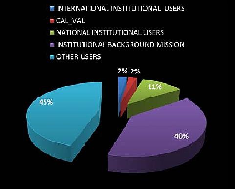
Due to the implementation of this acquisition plan, the system exploitation increased considerably, reaching a percentage of exploitation in the civilian domain in the range 80%-100% in the last year. The trend of the COSMO-SkyMed Background Mission starting from May 2011 is visible in Figure 40.
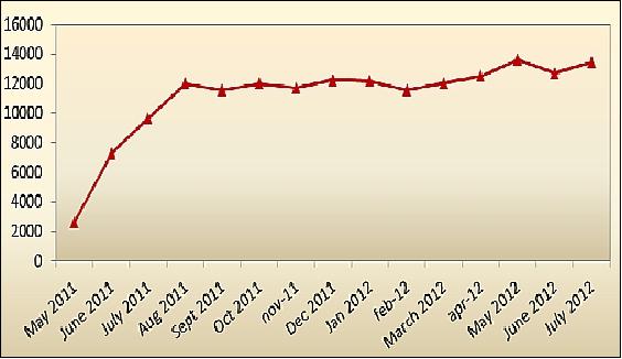
In the second part of 2011, the first interferometric coverage of Kenya was completed within the framework of the first interferometric mapping program of the African continent (Figure 41). The Kenya mapping project was undertaken, in addition to the Background Mission functions, using the Stripmap/HIMAGE acquisition mode with a 40 km x 40 km nominal swath, 3 m (single look) spatial resolution, and with the following main data take elements: polarization VV; right looking acquisitions; ascending orbit passes; incidence angle in the range of 20°-25°.
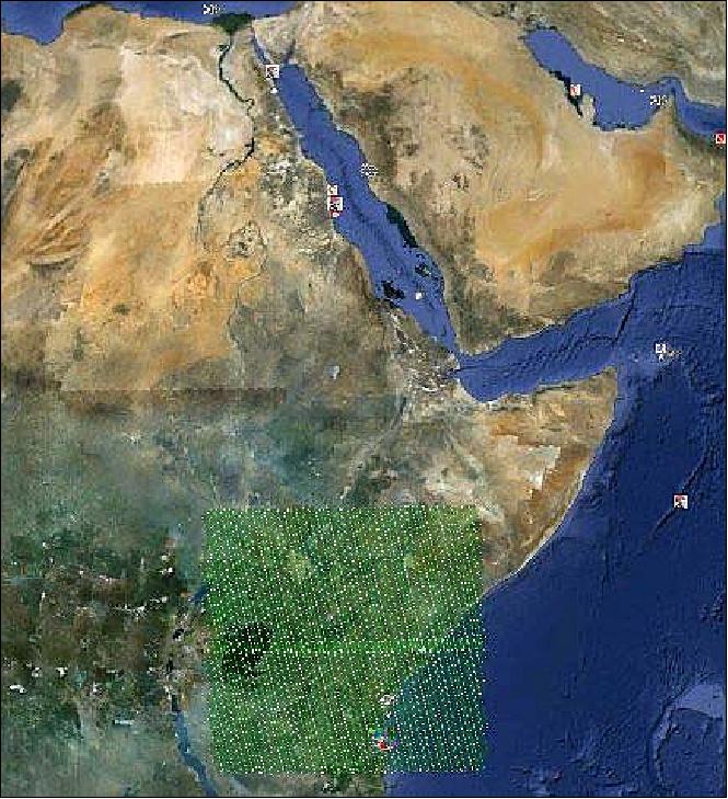
The total number of COSMO-SkyMed Stripmap data takes for a single mapping is close to 1600. The main goal of performing an (iterative) Kenya Interferometric Background Mission was to provide a specific data archive for demonstration purposes:
- Obtain a regional coverage data set archived using the best swath/resolution
- Obtain the necessary data to support land use, land cover change, oil spill, inland waters monitoring and emergency management (volcanoes, floods, etc.)
- Obtain a time-series interferometric archive for change detection applications
- Support specific technical training in Kenya and new research projects/ new services based on Earth Observation data.
The following Figures 42 and 43 give an example of COSMO-SkyMed acquired data over the Malindi area and Nairobi city.
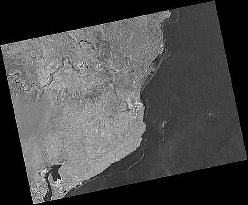
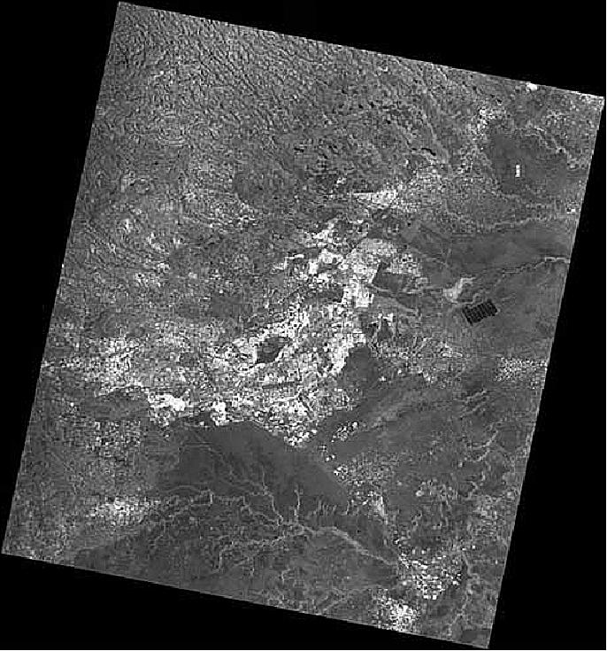
In January 2012, the Background Mission program started with the planning of a set of interferometric acquisitions over Sweden and over countries with high seismic risk: Japan, Iran, New Zealand (Ref. 92).
References
1) C. Galeazzi, C. Portelli, "The SkyMed/COSMO Platform Preliminary Definition," Proceedings of the 4th International Symposium on Small Satellites Systems and Services, Sept. 14-18, 1998, Antibes Juan les Pins, France
2) L. Candela, F. Caltagirone, COSMO-SkyMed: Mission Definition, Main Applications and Products," URL: http://earth.esa.int/workshops/polinsar2003
/participants/rum74/skymed.pdf
3) F. Caltagirone, G. Angino, A. Coletta, F. Impagnatiello, A. Gallon, "COSMO-SkyMed Program: Status and Perspectives," Proceedings of Third International Workshop on Satellite Constellations and Formation Flying, Pisa, Italy, Feb. 24-26, 2003
4) M. Di Lazzaro G. Angino M. Piemontese, A. Capuzi, R. Leonardi, "COSMO-SkyMed: The Dual-Use Component of a Geospatial System for Environment and Security," Proceedings of the 2008 IEEE Aerospace Conference, Big Sky, MT, USA, March 1-8, 2008, paper: 2.1002
5) Alessandro Coletta, Giuseppe Angino, Fabrizio Battazza, Francesco Caltagirone, Fabrizio Impagnatiello, Giovanni Valentini, Arnaldo Capuzi, Sandro Fagioli, Roberto Leonardi, "COSMO-SkyMed Program: Utilization and Description of an Advanced Space EO Duel-Use Asset," Envisat Symposium, Montreux, Switzerland, April 23-27, 2007, URL: http://earth.esa.int/workshops/envisatsymposium/
proceedings/sessions/5D2/587954co.pdf
6) Mario Cossu, Luigi Corsano, Michelangelo L'Abbate, Marco Mappini, Rita Roscigno, Marco Sacchettino, Roberto Sigismondi, Paolo Venditti, "From large to small Earth Observation satellites: wide range of applications for Data Handling and Transmission Payload," Proceedings of the 60th IAC (International Astronautical Congress), Daejeon, Korea, Oct. 12-16, 2009, IAC-09.D1.2.2
7) A. Intelisano, L. Mazzini, A. Notarantonio, S. Landenna, A. Zin, L. Scaciga, L. Marradi, "Recent Flight Experiences of TAS-I On-board Navigation Equipments," Proceedings of NAVITEC 2008, 4th ESA Workshop on Satellite Navigation User Equipment Technologies GNSS User Technologies in the Sensor Fusion Era, Dec. 10-12, 2008, Noordwijk, The Netherlands
8) A. Csizmar, L. Richards, E. Scorzafava, G. Daprati, G. Perrone, "COSMO-SkyMed, First Lithium-Ion Battery for Space-based Radar," Proceedings of the 7th European Space Power Conference, Stresa, Italy, May 9-13, 2005, ESA SP-589
9) G. M. Perusini, E. Scorzafava, "The 800 Amps Wide Range BUS Current Sensor for COSMO-SkyMed Satellite," Proceedings of the 7th European Space Power Conference, Stresa, Italy, May 9-13, 2005, ESA SP-589
10) E. Scorzafava, C. Galeazzi, R. Campesato, C. Casale, G. Gabetta, C. Flores ,N. Fatemi, P. Sharps, B. Clevenger, G. Daprati, G. Perrone, L. Croci, F. Rizzi, "COSMO-SkyMed EPS, Advanced Multijunction Solar Cells, Manufacturing & Testing," Proceedings of the 7th European Space Power Conference, Stresa, Italy, May 9-13, 2005, ESA SP-589
11) Marco Manfreda, Stefano Costantini, Luciano Croci, Guido Gianninoto, Edmondo Scorzafava, "COSMO-SkyMed Electrical System In Flight Performances;" Proceedings of the 8th European Space Power Conference, Constance, Germany, Sept. 14-19, 2008, ESA SP-661, Sept. 2008
12) ASI Agency Report on Earth Observation Activities "20th CEOS Plenary meeting", Buenos Aires, Argentina, November, 2006
13) "Boeing Launches 4th Earth-Observation Satellite for Italy," Nov. 6, 2010, URL: http://boeing.mediaroom.com/2010-11-06-Boeing-Launches
-4th-Earth-Observation-Satellite-for-Italy
14) L. Amorosi, A. Notarantonio, E. Calio, A. Ritorto, C. Galleazzi, "COSMO-Skymed constellation control: hardware and software implications," Proceedings of IAC 2004, Vancouver, Canada, Oct. 4-8, 2004, IAC-04-A.2.04
15) A. Albanese, L. Mazzini, C. Galeazzi, E. Scorzafava, "COSMO-SkyMed Constellation Maintenance using POD and COD Onboard Functions," Proceedings of Third International Workshop on Satellite Constellations and Formation Flying, Pisa, Italy, Feb. 24-26, 2003
16) "COSMO-SkyMed Mission - COSMO-SkyMed System Description & User Guide," ASI, URL: http://www.e-geos.it/products/pdf/csk-user_guide.pdf
17) Francesco Caltagirone, Arnaldo Capuzi, Sandro Fagioli, Guiseppe Angino, Fabrizio Impagnatiello, "COSMO-SkyMed: The Earth Observation Italian Constellation for Risk Management and Security," SpaceOps 2006, Rome, Italy, June 19-23, 2006, AIAA 2006-5500
18) G. Fasano, M. D'Errico, "Gathering SAR Data Under Different Bistatic Angle: A New Potential of COSMO-SkyMed Constellation," Proceedings of the 5th Symposium on Small Satellites for Earth Observation, April 4-8, 2005, Berlin, Germany
19) "COSMO-SkyMed System Description & User Guide," Doc. No: ASI-CSM-ENG-RS-093-A, May 4, 2007, URL: http://www.cosmo-skymed.it/docs/ASI-CSM-ENG-RS
-093-A-CSKSysDescriptionAndUserGuide.pdf
20) Diego Calabrese, Andrea Torre, Axel Oddone,Annamaria Nicito, Silvio G. Neglia,Giuseppe F. De Luca, Alessandro Coletta, Francesco Nirchio, Carlo De Libero, "COSMO-SkyMed mission status," EUSAR 2018 (12th European Conference on Synthetic Aperture Radar), Aachen, Germany, June 4-7, 2018
21) "Happy Birthday COSMO-SkyMed #10," ASI, 5 Dec. 2017, URL: [web source no longer avaliable]
22) Maria Libera Battagliere, Maria Virelli, Giuseppe F. De Luca, Alessandro Coletta, "Status and Perspectives of the International Cooperation based on the Italian EO space asset COSMO-SkyMed," Proceedings of the 68th IAC (International Astronautical Congress), Adelaide, Australia, 25-29 Sept. 2017, paper: IAC-17-B.1.1.6
23) Valerio Grimani, Alessandro Cricenti, Andrea Perrera, Mario Cossu, Francesco Caltagirone, Claudia Anita Maria Fiorentino, Silvia Mari, Manfredi Porfilio, Giuseppe Francesco De Luca, Stefano Serva, Paolo Inversi, Pier Giorgio Esposito, "COSMO-SkyMed: From the first towards the second generation," Proceedings of the 67th IAC (International Astronautical Congress), Guadalajara, Mexico, Sept. 26-30, 2016, paper: IAC-16,B1,2,9
24) Agnese Cerroni, "COSMO's eyes on the earthquake: The Italian COSMO-SkyMed satellite constellation provides the first images of the damage caused to towns by the 6.0 magnitude earthquake on 24 August," ASI news, August 29, 2016, URL: http://www.asi.it/en/news
/cosmos-eyes-earthquake
25) Valerio Grimani, Barbara Bussi, Pasquale Salemme, Andrea Perrera, Paolo Inversi, Pier Giorgio Esposito, Axel Oddone, Giuseppe Francesco De Luca, Alessandro Coletta, "CSK mission status and experimentation results," Proceedings of EUSAR 2016, 11th European Conference on Synthetic Aperture Radar, Hamburg, Germany, June 6-9, 2016
26) Patrizia Sacco, Maria Libera Battagliere, Alessandro Coletta, "COSMO-SkyMed mission status: results, lessons learnt and evolutions," Proceedings of the IGARSS (International Geoscience and Remote Sensing Symposium) 2015, Milan, Italy, July 26-31, 2015
27) Information provided by Patricia Sacco of ASI, Rome, Italy
28) "COSMO-SkyMed for Science and SMEs-ASI is offering satellite constellation data free of charge to the international scientific community and SMEs in two separate Open Calls, for developing civilian applications," ASI, Feb. 25, 2015, URL: http://www.asi.it/en/news/
cosmoskymed_for_science_and_smes
29) "COSMO-SkyMed Constellation: data utilization," ASI, Feb. 25, 2015, URL: http://www.asi.it/en/agency/bandi_en
/calls/cosmoskymed_open_call_for_science
30) Peter B. de Selding, "Italian Commitment to Next-gen Radar Satellites in Time to Avert Gap," Space News, January 21, 2015,, URL: http://spacenews.com/italian-commitment-
to-next-gen-radar-satellites-in-time-to-avert-gap/
31) "NASA Analyses of Global Positioning System Data and Italian Radar Satellite Data Reveal Napa Quake Ground Deformation," NASA/JPL, Sept. 4, 2014, URL: http://www.jpl.nasa.gov/
spaceimages/details.php?id=PIA18798
32) Hook Hua, Susan Owen, Sang-Ho Yun, Paul Lundgren, Angelyn Moore, Piyush Agram, Gian Franco Sacco, Eric Fielding, Paul Rosen, Frank Webb, Mark Simons, Alexander Smith, Brian Wilson, Timothy Stough, Peter F. Cervelli, Michael Poland, "The Advanced Rapid Imaging and Analysis for Monitoring Hazards (ARIA-MH) Science Data System," ESTF 2014 (Earth Science Technology Forum), Leesburg, VA, USA, Oct. 28-30, 2014, URL: http://esto.nasa.gov/forum/estf2014
/presentations/A7P1_Hua.pdf
33) "Cosmo-SkyMed satellites studying California earthquake," ASI, Sept. 2, 2014, URL: https://www.researchitaly.it/en/understanding/press-media
/news/cosmo-skymed-satellites-studying-california-earthquake/
34) Elvira Caliò, Barbara Bussi, Annamaria Nicito, Manfredi Porfilio, Stefano Serva, "COSMO-SkyMed: operational results and performance," Proceedings of EUSAR 2014 (10th European Conference on Synthetic Aperture Radar), Berlin, Germany, June 3-5, 2014
35) https://earth.esa.int/web/guest/missions/
3rd-party-missions/current-missions/cosmo-skymed
36) Donatella Giampaolo, "COSMO-SkyMed & the Arctic - The new frontier of Ice Charting Services," 14th Meeting of the IICWG (International Ice Charting Working Group), Reykjavík, Iceland, October 21-25, 2013, URL: http://nsidc.org/noaa/iicwg/presentations/IICWG
-2013/Giampaolo_COSMO_SkyMed_and_the_Arctic.pdf
37) Fabio Covello, Maria Libera Battagliere, Alessandro Coletta, "The contribution of the COSMO-SkyMed space system in the international context," Proceedings of the ESA Living Planet Symposium, Edinburgh, UK, Sept. 9-13, 2013 (ESA SP-722, Dec. 2013)
38) F. Covello, "Disaster and emergency management: the contribution of the Italian Space System COSMO-SkyMed," Proceedings of the 50th Session of Scientific & Technical Subcommittee of UNCOPUOS, Vienna, Austria, Feb. 11-22, 2013, URL: http://www.oosa.unvienna.org
/pdf/pres/stsc2013/tech-52E.pdf
39) "The COSMO-SkyMed light on the 'Geohazard Supersites'," ASI, June 12, 2012, URL: http://www.asi.it/en/news/the_cosmoskymed
_light_on_the_geohazard_supersites
40) Maria Angelucci, Donatella Giampaolo, "COSMO-SkyMed e-GEOS Supports Development of Innovative Services," 13th IICWG (International Ice. Charting Working Group), Tromsø, Norway, October 15-19, 2012, URL: http://nsidc.org/noaa/iicwg/presentations
/IICWG-2012/Angelucci_COSMO_SkyMed_e-GEOS.pdf
41) "New COSMO-SkyMed Receiving Station in the Arctic," e-GEOS, June 28, 2012, URL: http://www.e-geos.it/news/12-06-28-fmi/index.html
42) Ken Kremer, "Amazing Radar Image from Space Highlights Costa Concordia Catastrophe," Universe Today, Jan. 20, 2012, URL: http://www.universetoday.com/92777/amazing-radar-
image-from-space-highlights-costa-concordia-catastrophe/
43) "KSAT, ConocoPhillips and e-GEOS (ASI/Telespazio) sign contract to monitor ice formation and movement using the COSMO-SkyMed constellation," e-GEOS, January 11, 2012, URL: http://www.e-geos.it/news/12-01-11-ksat/index.html
44) L. Pietranera, L.Cesarano, V. Gentile, F.Britti, F.Strehl, ,A.. Relin,R. Siegmund, "Time and resolution : COSMO-SkyMed VHR data in support to precision farming applications," 17th GEOCAP Conference 'Geomatics in Support of the CAP' Tallinn, Estonia, November 24, 2011, URL: http://mars.jrc.ec.europa.eu/mars/content/download
/2426/12527/file/12_CSK_precision%20farming.pdf
45) Maria Libera Battagliere, Fabio Covello, Alessandro Coletta, "Cosmo-SkyMed constellation fully deployed: overview and exploitation," Proceedings of IAC 2011 (62nd International Astronautical Congress), Cape Town, South Africa, Oct. 3-7, 2011, paper: IAC-11-B1.5.2
46) Andrea Torre, Diego Calabrese, Manfredi Porfilio, "COSMO-SkyMed: Image quality achievements," RAST 2011 (Recent Advances in Space Technologies) Conference, Istanbul, Turkey, June 9-11, 2011
47) Alessandro Coletta, Maria Libera Battagliere, Valentina Bellifemine, Franco Brizio, Laura Candela , Fabio Covello, Giovanni Milillo," Exploitation of COSMO-SkyMed Mission: Preliminary Results using the one-day Configuration," Proceedings of the ESA Living Planet Symposium, Bergen Norway, June 28-July 2, 2010, ESA SP-686, December 2010
48) "The Italian satellite COSMO-SkyMed 4 reaches its final orbit and is transmitting its first images," Dec. 16, 2010, Telespazio,TAS, URL: https://web.archive.org/web/20160326011506/https://www.thalesgroup.com/en/content/italian-satellite-cosmo-skymed-4-reaches-its-final-orbit-and-transmitting-its-first-images
49) Giuseppe Francesco De Luca, Francesco Caltagirone, Gianni Casonato, Graziano Marano, Andrea Gallon, Attilio Santellocco, "COSMO SkyMed Lessons Learned: Efficiency and Efficacy parameters to measure the system of systems effectiveness," Proceedings of the SpaceOps 2010 Conference, Huntsville, ALA, USA, April 25-30, 2010, paper: AIAA 2010-2242
50) "COSMO SkyMed System Begins Full Operations," Space News, October 26, 2009, p. 10
51) G. Valentini, F. Covello, F. Battazza, A. Coletta, G. Manoni, "COSMO-SkyMed Mission: first results and future outlook," Proceedings of the 60th IAC (International Astronautical Congress), Daejeon, Korea, Oct. 12-16, 2009, IAC-09.B1.6.1
52) F. Covello, F. Battazza, A. Coletta, G. Manoni, G. Valentini, "COSMO-SkyMed Mission Status: Three out of Four Satellites in Orbit," Proceedings of IGARSS (IEEE International Geoscience and Remote Sensing Symposium) 2009, Cape Town, South Africa, July 12-17, 2009
53) Fabrizio Battazza, Giuseppe Bianco, Alessandro Coletta, "COSMO-SkyMed Mission: Status, System Access and Data Exploitation," abstract, 6th Conference on Image Information Mining at EUSC (European Union Satellite Center), Torrejon Air Base, Madrid, Spain, November 3-5, 2009
54) Giovanni Valentini, Fabrizio Battazza, Alessandro Coletta, Fabio Covello, Gemma Manoni, "Achievements and Perspectives of the COSMO-SkyMed Mission," Progress In Electromagnetics Research Symposium, Proceedings, Moscow, Russia, August 18 - 21, 2009
55) http://www.asi.it/en/news_en/the_
first_three_images_from_cosmoskymed_3_0
56) http://www.asi.it/en/agency/companies/e-geos
57) Paolo Rutigliano, "e-GEOS Multimission Ground Segment, from GeoEye and COSMO-SkyMed data provision to Sentinel reception," 3rd GSCB (Ground Segment Coordination Body) Workshop, 2012, ESA/ESRIN, Frascati, Italy, June 6-7, 2012, URL: http://earth.esa.int/gscb/papers/
2012/28-e-GEOS_Presentations.pdf
58) Fabrizio Battazza, Alessandro Coletta, Fabio Covello, Ettore Lopinto, Luca Pietranera, Giovanni Valentini, Simona Zoffoli, "COSMO-SkyMed Mission Status," Proceedings of the 59th IAC (International Astronautical Congress), Glasgow, Scotland, UK, Sept. 29 to Oct. 3, 2008, IAC-08-B1.2.9
59) Giovanni Valentini, "COSMO-SkyMed Mission Stauts," 2nd International Workshop on Advances in SAR Oceanography from Envisat and ERS Missions, Jan. 21-25, 2008, Frascati, Italy, URL: http://earth.esa.int/workshops/seasar2008
/participants/272/pres_272_coletta.pdf
60) Fabrizio Battazza, "COSMO-SkyMed Mission Status," IPY STG§ (Space Task Group 3) Meeting, Frascati, Italy, May 5-6, 2008, URL: http://bprc.osu.edu/rsl/GIIPSY/documents
/05%20Battazza_COSMO-SkyMed_IPY-STG3.pdf
61) L. Candela, F. Caltagirone, "COSMO-SkyMed: Mission Definition, Main Applications and Products," Proceedings of POLinSAR (Polarimetry and Polarimetric Interferometry) Workshop, ESA/ESRIN, Frascati, Italy, Jan. 14-16, 2003
62) P. Lombardo, "A Multichannel Spaceborne Radar for the COSMO-Skymed Satellite Constellation," Proceeding of the IEEE Aerospace Conference, Big Sky, MT, USA, March 6-13, 2004
63) A. Torre, P. Capece, "COSMO-SkyMed: the advanced SAR instrument," RAST 2011 (Recent Advances in Space Technologies) Conference, Istanbul, Turkey, June 9-11, 2011
64) P. Capece, G. Sirocchi, V. Santachiara, R. Trento, A. Capuzi, E. Stopponi, "X band active SAR Antenna Architecture for Cosmo-Sky Med Mission," 25th Antenna Workshop on Satellite Antenna Technology, Sept. 18-20, 2002, ESA/ESTEC
65) G. R. Verdone, R. Viggiano, E. Lopinto, et al., "Processing Algorithms for COSMO-SkyMed SAR Sensor," Proceedings of IGARSS 2002, Toronto, Canada, June 24-28, 2002
66) F. Caltagirone, P. Spera, G. Manoni, L. Bianchi, "COSMO-SkyMED: A Dual Use Earth Observation Constellation," Proceedings of 2nd International Workshop on Satellite Constellations and Formation Flying, Feb. 19-20, 2001, Haifa, Israel
67) A. Coletta, "COSMO-SkyMed Mission: Application and Data Access," ESA Advanced Training Course on Land Remote Sensing, Prague, Czech Republic, June 29, 2009
68) A. Torre, P. Capece, "COSMO-SkyMed SAR Instrument Calibration Approach," Proceedings of EUSAR 2006, Dresden, Germany, May 16-18, 2006
69) S. Falzini, V. Speziale, E. De Viti, "COSMO-SkyMed Active Calibrator: a sophisticated tool for SAR image calibration," Proceedings of IGARSS 2007 (International Geoscience and Remote Sensing Symposium), Barcelona, Spain, July 23-27, 2007
70) P. Lombardo, D. Pastina, F. Colone, F. Gini, F. Lombardini, F. Dell'Acqua, P. Gamba, V. Pascazio, G. Pelosi, C. Riminesi, G. Cucinella, G. Perrotta, R. Battaglia, "A study for COSMO-SkyMed SAR Multi-Beam of Second Generation (MSAR-2G)," POLinSAR Workshop 2005, Jan. 17-21, 2005, ESA/ESRIN, Frascati, Italy, http://earth.esa.int/workshops/polinsar2005/participants
/156/paper_CR_PolinSAR05_Lombardo_etalii.pdf
71) P. Lombardo, F. Colone, D. Pastina, "Monitoring and surveillance potentialities obtained by splitting the antenna of the COSMO-SkyMed SAR into multiple sub-apertures," IEE Proceedings, `Radar, Sonar and Navigation,' April 13, 2006, Vol. 153, Issue 2, pp. 104-116
72) Marco D'Errico, Giancarmine Fasano, "Design of interferometric and bistatic mission phases of COSMO/SkyMed constellation," Acta Astronautica, Volume 62, Issues 2-3, January-February 2008, pp. 97-111
73) F. Caltagirone, A. Capuzi, A. Coletta, C. Galeazzi, E. Lopinto, A. Moccia, "SABRINA the Italian Mission for Endowing COSMO-SkyMed with Bistatic and Interferometric Capabilities," Proceedings of EUSAR 2006, Dresden, Germany, May 16-18, 2006
74) C. Galeazzi, M. Marcozzi, L. Mazzini, G. Campolo, C. Bruno, "Formation Control for SABRINA Mission," SpaceOps 2006 Conference, Rome, Italy, June 19-23, 2006, AIAA 2006-5682
75) A. Coletta, C. Galeazzi, F. Caltagirone, E. Scorzafava, L. Amorosi, E. Calio, A. Notarantonio, A. Moccia, "Interferometric Missions: Applications within ASI Space Programs," SpaceOps 2006 Conference, Rome, Italy, June 19-23, 2006
76) A. Renga, A. Moccia, M. D'Errico, S. Dellepiane, E. Angiati, G. Vernazza, P. Lombardo, F. Colone, M. Sedehi, D. Cristallini, S. Pignataro, Q. Rioli, G. Milillo, C. Bruno, F. Di Giorgio, M. Labriola, "From the Expected Scientific Applications to the Functional Specifications, Products and Performance of the SABRINA Missions," IEEE Radar Conference, Rome, Italy, May 26-30, 2008, pp. 1117–1122
77) "Pleiades to succeed SPOT," CNES Magazine No 9, June 2000, p. 8
78) A. Baudoin, "The Current and Future SPOT Program," Proceedings of the ISPRS Joint Workshop `Sensors and Mapping from Space 1999,' Sept. 27-30, 1999, Hannover, Germany
79) In Greek mythology, Pleiades refers to the seven daughters of the Titan Atlas and the Oceanid Pleione: Maia, Electra, Taygete, Celaeno, Alcyone, Sterope, and Merope. They all fell in love with gods (except Merope, who loved a mortal) and were the mothers of gods. The Pleiades eventually formed a constellation.
80) G. F. De Luca, "COSMO-SkyMed: A Dual System Architecture providing Interoperability, Expandability, and Multi-sensor (IEM) capabilities," SpaceOps 2006, Rome, Italy, June 19-23, 2006
81) G. F. De Luca, F. Caltagirone, G. Marano, G. Casonato, M. Piemontese, A. Coletta, B. Versini, M. De Carlo, "Interoperability, Expandability And Multi Mission/Sensor COSMO-SkyMed Capabilities," Proceedings of IGARSS 2007 (International Geoscience and Remote Sensing Symposium), Barcelona, Spain, July 23-27, 2007
82) "Earth Watch Program: COSMO-SkyMed Element," ESA/PB-EO (2001) 55, May 18, 2001, with Annex: Draft Italian Earth Watch Program Proposal - ESA participation to COSMO-SkyMed Mission (Radar Component)
83) A. Giros, "ORFEO preparatory program - from PLEIADES and COSMO images to useful information," 4th ESA-EUSC (European Union Satellite Centre) 2006 Conference, Nov. 27-29, 2006, Madrid, Spain
84) Duality, Interoperability, Expandability, Multi Mission capabilities of the COSMO COSMO-SkyMed Ground Segment: a challenge becoming reality," European Ground System Architecture Workshop (ESAW), June 12-13, 2007, ESA/ESOC Darmstadt, Germany
85) G. Rum, L. Candela, "Italian Research and Development Activities Towards Full Use of COSMO-SkyMed and the Future European Systems," ESA-EUSC 2004, Madrid, Spain, March 17-18, 2004
86) COSMO-SkyMed - Keeping an Eye on the World," ESA, URL: http://earth.eo.esa.int/landtraining09
/COSMO_SkyMed_System_1.pdf
87) Fabio Covello, Maria Libera Battagliere, Alessandro Coletta, "Overview and exploitation of the fully deployed COSMO-SkyMed constellation," Proceedings of the 63rd IAC (International Astronautical Congress), Naples, Italy, Oct. 1-5, 2012, paper: IAC-12-B1.6.7
88) G. Casonato, G. F. De Luca, G. Marano, "COSMO-SkyMed Expandability at work: French Center and Commercial User Terminals ready to operate," Proceedings of the SpaceOps 2010 Conference, Huntsville, ALA, USA, April 25-30, 2010, paper: AIAA 2010-2019
89) Giuseppe Francesco De Luca, Gianni Casonato, Fabio D'Amico, Claudia Anita Maria Fiorentino, Manfredi Porfilio, Andrea Cecchini, Franco Nardone, Elvira Caliò, Tiziana D'Ignazio, Mario Profili, Anna Croce, Fabrizio Faenza, Federica Russo, Antonio Trapasso, "Proceedings of IAC 2011 (62nd International Astronautical Congress), Cape Town, South Africa, Oct. 3-7, 2011, paper: IAC-11.B1.1.5
90) E. Lopinto, "COSMO-SkyMedProducts and User Services," 2006, URL: http://www.oosa.unvienna.org
/pdf/pres/stsc2006/ind-07.pdf
91) COSMO-SkyMed Solutions for Ground Segment Expandability and Interoperability," Ground System Architecture Workshop 2008, April 1-3, 2008, Manhattan Beach, CA, USA
92) Maria Libera Battagliere, Fabio Covello, Alessandro Coletta, "COSMO-SkyMed Background Mission: overview, objectives and results," Proceedings of the 63rd IAC (International Astronautical Congress), Naples, Italy, Oct. 1-5, 2012, paper: IAC-12-B1.5.12
Spacecraft Launch Mission Status Sensor Complement Ground Segment References Back to top