Coriolis/WindSat
EO
Multiple direction/polarisation radiometers
Atmosphere
Ocean
Quick facts
Overview
| Mission type | EO |
| Agency | DoD (USA) |
| Mission status | Mission complete |
| Launch date | 06 Jan 2003 |
| End of life date | 31 Dec 2020 |
| Measurement domain | Atmosphere, Ocean, Snow & Ice |
| Measurement category | Cloud particle properties and profile, Radiation budget, Surface temperature (ocean), Sea ice cover, edge and thickness, Snow cover, edge and depth, Ocean surface winds |
| Measurement detailed | Cloud liquid water (column/profile), Sea surface temperature, Wind vector over sea surface (horizontal), Sea-ice cover, Wind speed over sea surface (horizontal), Snow water equivalent, Snow melting status (wet/dry), Long-wave Earth surface emissivity |
| Instruments | WindSat |
| Instrument type | Multiple direction/polarisation radiometers |
| CEOS EO Handbook | See Coriolis/WindSat summary |
Coriolis/WindSat
Spacecraft Launch Mission Status Sensor Complement References
Overview
Coriolis is a US DoD satellite technology demonstration mission within the US Air Force STP (Space Test Program), sponsored by SPAWAR (Space and Naval Warfare Systems Command) of the US Navy and by NPOESS/IPO, managed by NRL, and implemented by AFRL (Air Force Research Laboratory) and NRL (Naval Research Laboratory). Coriolis is also referred to as STP mission P98-2.
The overall objective is to conduct an operational verification of new instrument technology, aimed at validating spaceborne multichannel polarimetric radiometry as a reliable and cost effective means for achieving wind vector measurements (speed and direction) that meet NPOESS (National Polar-orbiting Operational Environmental Satellite System) requirements. A further objective of the Air Force is to monitor solar activity for better predictive models of solar storms. 1) 2) 3)
Spacecraft
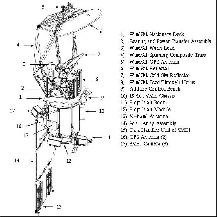
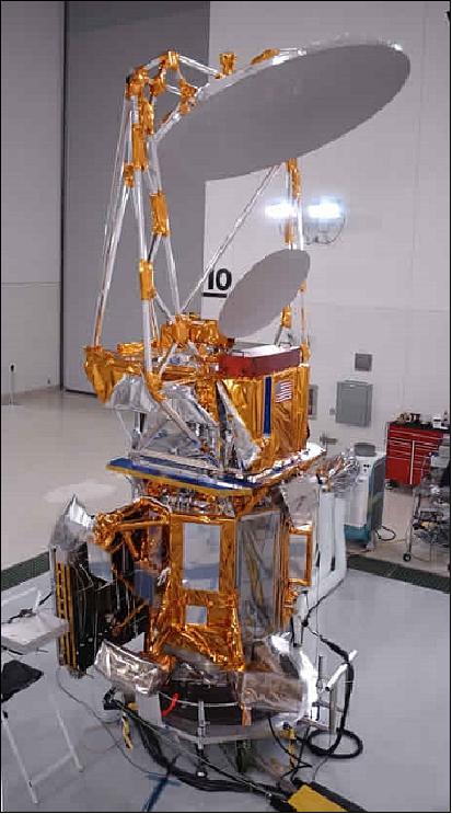
Coriolis is a fully redundant three-axis stabilized spacecraft (nadir pointing) built by the contractor Spectrum Astro Inc. of Gilbert, AZ (now General Dynamics) for the U.S. Navy. The S/C bus is based on the SA-200HP catalog bus, an Al honeycomb/Al facesheet deck structure, as flown on DS1 (Deep Space 1), with specific tailoring to suit the Coriolis requirements. The overall dimensions are: 4.69 m height (without solar array), 1.34 m diameter. Power is provided by a solar array assembly (dual-junction GaAs solar cells, 1.174 kW at EOL) and by a single 50 Ah NiH2 battery for ecliptic period operations. Attitude sensing is provided by autonomous sun acquisition using coarse sun sensors and magnetometers, actuation is provided by reaction wheels (pitch momentum biased). GPS-based orbit knowledge of < 100 m, 10 cm/s, all axes. A hydrazine propulsion system is used for orbit transfer. The S/C has a total launch mass of 827.4 kg (S/C bus of 377 kg), the design life is three years.
Key features of the Coriolis spacecraft design include extremely low levels of electromagnetic interference for compatibility with the ultra-sensitive WindSat radiometer (e.g., radiated emissions are < 6.5 dB µV/m at 6.8 GHz); and a system architecture to support the 30 rpm yaw spin of WindSat's rotating assembly, while providing power plus precise attitude knowledge and control.
Vehicle envelope | 6.9 m high x 3.0 m diameter, deployed |
Spacecraft mass | 827.4 kg, S/C bus of 377 kg, propellent of 82 kg |
Orbit average power consumption | 725 W, (271 W bus, 454 W payload) |
Design life | 3 years with a goal of 5 years |
Radiation tolerance | 26 krad total dose |
RF Communications
Command and data handling is provided by a VME-based architecture and a MIL-STD-1553B bus. An onboard solid-state recorder of 30 Gbit capacity is provided. TT&C communications are provided in S-band (128 kbit/s downlink, 2 kbit/s encrypted uplink). Instrument data are downlinked in X-band at 25.6 or 51.2 Mbit/s (use of CCSDS protocols). The US Navy uses a real-time S-band tactical downlink (256 kbit/s) to distribute radiometer data to deployed fleet units. AFSCN (Air Force Satellite Control Network) provides S/C operations in S-band.
Launch
The Coriolis/WindSat spacecraft was launched on 6 January 2003 aboard a Titan 2 rocket from VAFB, CA.
Orbit
Sun-synchronous circular orbit, altitude = 840 km, inclination = 98.7º, period = 101 minutes, revisit time of 8 days, the longitude of the ascending node shifts westward by 138 km daily; local time of ascending node (LTAN) is 18:00 hours.
Mission Status
• January 16, 2019: The WindSat/Coriolis mission is operating nominally according to the NRL website. The mission is now 16 years on orbit. 4)
• August 2017: In 2003, the Coriolis mission was launched with two experiments: the Navy's WindSat experiment which measured ocean surface wind speed and direction, and the AFRL SMEI (Solar Mass Ejection Imager), which detected solar mass ejections moving towards Earth. The satellite is still in operation today and the data from WindSat is used operationally. The technology demonstrated in the WindSat experiment is the basis for several planned follow-on missions. 5)
• July 2017: The NRL WindSat geophysical model has been updated to improve the modeling of atmospheric propagation, sea surface emissivity and receiver frequency passband effects. Work is ongoing to utilize the updated model in calibration analyses and an updated retrieval algorithm. This work will include and analysis to verify that the receiver frequency passband effects shown in the model are consistent with the WindSat measurements. WindSat ocean vector wind retrievals are retrieved in near-real-time using the NRL (Naval Research Laboratory) retrieval algorithm and operationally assimilated into numerical weather prediction global models. The retrieval algorithm utilizes a parameterized geophysical model for the modified Stokes components at the frequencies of the measured WindSat brightness temperatures. The algorithm simultaneously retrieves the ocean surface vector wind, SST (Sea Surface Temperature), PWV (Precipitable Water Vapor) and columnar CLW (Cloud Liquid Water). The model must be accurate to on the order of 0.1 K to support wind vector retrievals due to the small magnitude of the wind direction signal. An accurate geophysical model is also required to support instrument calibration. The project has updated the initial model by including the wind direction dependence of the sea surface emissivity for the vertical and horizontal polarizations and basing the model on a different one dimensional atmospheric radiative transfer model. The project has also modeled all of the WindSat channels instead of only the modeling the modified Stokes parameters. The updated model also accounts for differences in the frequency passbands of the individual WindSat receivers. 6)
Frequency (GHz) | Polarizations | BW (Bandwidth) MHz | EIA (Earth Incidence Angle, deg) | IFOV (Instantaneous Field of View), km |
6.8 | V, H | 125 | 54.0 | 39 x 71 |
10.7 | V, H, P, M, L, R | 300 | 50.3 | 25 x 38 |
18.7 | V, H, P, M, L, R | 750 | 55.9 | 16 x 27 |
23.8 | V, H | 500 | 53.5 | 20 x 30 |
37.0 | V, H, P, M, L, R | 2000 | 53.5 | 8 x 13 |
Figure 4: WindSat instrument parameters
• 2012: The Coriolis/WindSat mission continues to operate nominally (in its 10th year on orbit). No life-limiting trends have been identified. WindSat polarimetric microwave radiometer data are used operationally in numerical weather prediction (NWP) models by the US Navy, NOAA NCEP and the UK Met Office. Furthermore, products such as imagery, wind fields, sea ice concentration, and sea surface temperature are being used by a variety of operational users: Joint Typhoon Warning Center, Naval Oceanographic Office, NWS Forecasting Offices, and others.
• September 2011: The secondary payload, SMEI (Solar Mass Ejection Imager), has been powered off due to electrical power limitations.
• 2011: Coriolis/WindSat continues to operate successfully. There were no major issues or events regarding the satellite or payloads in 2010. WindSat data is being used operationally by the US Navy and other agencies (NOAA/NCEP, UK Met Office, etc.). The system is not showing any significant signs of ageing/degradation. The mission is expected to continue as long as WindSat is providing useful data to the user community. In addition to surface wind vectors, other products like SST (Sea Surface Temperature), rain rate, cloud liquid water, total precipitable water (water vapor), and microwave imagery are being produced. Furthermore, sea ice, soil moisture, and land surface temperature products are being developed. 10) 11)
• January 2009: The SMEI instrument marked the 6th anniversary in orbit. It has amassed an unprecedented dataset of ~25,000 full-sky images since 2003 with a 102-minute cadence, 1° spatial resolution, and better than 8th magnitude sensitivity. However, SMEI is nearing the end of its life.
• June 2006: WindSat Brightness Temperature and Environmental Data Now Available to Science and User Community. 13)
• March 2006: The SMEI instrument experienced an irrevocable failure on its A-side electronics. As a consequence, SMEI was switched to the B-side and continues to operate nominally. Camera 3 (closest to the sun) has run above predicted/planned for temperatures and performance continually degrades with accumulated radiation dose. 12)
• June 2005: The recovery efforts of WindSat were successful, and the instrument returned to operations in late. 15)
• April 28, 2005: The Coriolis spacecraft was commanded to enter a sun-pointing mode of operation, rather than the normal reference-point mode. This successfully brought the Coriolis temperatures back within safe limits, but this pointing mode has significantly impacted the quality of data that is being returned by the SMEI instrument.
• April 25, 2005: The SMEI instrument performed diagnostic tests to attempt to resolve a technical issue. Unfortunately, after this test was completed, parts of the instrument were reaching critical temperature limits and a solution was needed.
• February 2005: The WindSat project began to make the near real-time wind data from WindSat available to operational weather centers such as FNMOC (Fleet Numerical Meteorology and Oceanography Center) of the US Navy, Monterey, CA, AFWA (Air Force Weather Agency) at Offutt Air Force Base (OAFB), Bellevue, Nebraska, and NCEP (National Centers for Environmental Prediction), USA. 14)
• February 13, 2005: WindSat experienced an anomaly and was put into a safe-hold mode while the problem was being investigated, eventually finding that the BAPTA (Bearing and Power Transfer Assembly) of the scan mechanism changed speed unexpectedly. Up to the time of the anomaly, the mission had been very successful (i.e., demonstration to use WindSat to measure the ocean surface winds).
Sensor Complement
WindSat (Wind Microwave Radiometer)
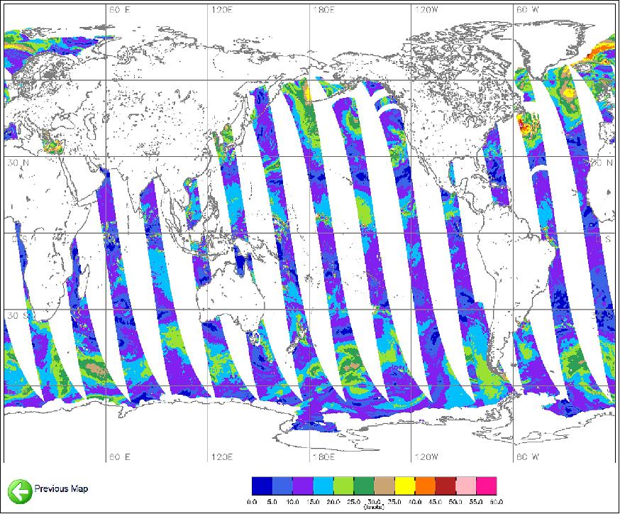
WindSat is a polarimetric microwave radiometer developed and built by NRL. WindSat is also considered a precursor instrument to CMIS (Conical-scanning Microwave Imager/Sounder), a radiometric polarimeter to be flown on NPOESS (National Polar-orbiting Operational Environmental Satellite System). The objective of WindSat is to conduct an operational demonstration of the WindSat system and to measure the ocean surface wind vector (speed and direction) for a number of practical applications (secondary measurements are sea surface temperature, rain rate and water vapor). WindSat also provides insight into such problems as the upwind/downwind asymmetry and boundary layer conditions (Ref. 1). 16)
The measurement principle makes use of the natural microwave emissions of the sea surface which vary with the degree of sea surface roughness. The rougher the seas, the more intense the emissions. The wind direction is obtained from the relationship between the horizontal and vertical polarization characteristics of the received signal and the anisotropic distribution of wind-driven waves. The wind vectors are estimated (model algorithm) by the measurement of multi-frequency polarimetric brightness temperatures. 17)
The WindSat microwave polarimetric radiometer consists of 22 channels of polarized brightness temperatures operating at five frequencies of 6.8, 10.7, 18.7, 23.8, and 37 GHz. All receivers are total power radiometers. The receivers at 10.7, 18.7 and 37.0 GHz are fully polarimetric; that is, they establish all four Stokes parameters by measuring the six principal polarizations [3 dual-polarization feed horns are used: V/H, ±45º linear, and Left/Right circular; the third and fourth Stokes parameters are formed by taking the brightness temperature difference between the ±45º polarizations, and the left- and right-hand circular polarization, respectively]. The 6.8 GHz channel is dual-polarimetric (vertical and horizontal) and provides sea surface temperature (SST) as a secondary product. The 23.8 GHz channel is also dual-polarimetric, its purpose is to correct for atmospheric water vapor which is unpolarized. The WindSat frequencies are useful beyond the measurement of ocean surface wind vectors and SST. Other parameters can be extracted/estimated from the data such as: atmospheric water vapor, cloud liquid water, rain rate, sea ice (age, concentration, and boundary), snow cover extent, and water content of snow. 18) 19)
Band (GHz) | Polarization | Bandwidth | EIA (Earth Incidence Angle) | IFOF (cell size) |
6.8 | V, H | 125 MHz | 53.5º | 40 km x 60 km |
10.7 | V, H, ±45, L, R | 300 MHz | 49.9º | 25 km x 38 km |
18.7 | V, H, ±45, L, R | 750 MHz | 55.3º | 16 km x 27 km |
23.8 | V, H | 500 MHz | 53.0º | 12 km x 20 km |
37.0 | V, H, ±45, L, R | 2 GHz | 53.0º | 8 km x 13 km |
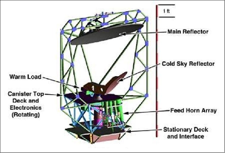
WindSat is a yaw-spinning instrument; it uses a conically scanned 1.83 m parabolic offset reflector with multiple feeds (11 dual-polarized feed horns). The antenna beams view the Earth at incidence angles ranging from 50-55º. The orbit and antenna geometry result in a forward-looking swath of about 1000 km. The placement of external calibration targets allows for an aft swath of 350 km. The availability of fore and aft swath geometry enables evaluation of one-look versus two-look wind vector retrieval techniques. The WindSat instrument has a mass of 341 kg and 350 W of power consumption.
Swath definition: The position and pointing of each feedhorn relative to the main reflector determines its unique, unobstructed swath. The intersection of the 11 individual swaths is identified as the WindSat common fore and aft swaths. While some frequency bands have a swath width > 1200 km in the forward direction, the common swath is about 950 km (68º of scan angle); the aft common swath is 350 km (23º of scan angle). The aft common swath does not contain the 6.8 GHz channel, for which the aft swath does not intersect the other channels due to the position of that feed on the edge of the feedhorn layout. 20)
Capability | NPOESS requirements | WindSat |
Horizontal resolution | 20 km | 25 km |
Mapping accuracy | 5 km | 5 km |
Measurement range | 3 - 25 m/s, 0 - 360º (direction) | 3 - 25 m/s, 0 - 360º (direction) |
Measurement precision |
|
|
Measurement accuracy |
|
|
The antenna/calibration subsystem consists of the main reflector, 11 feedhorns, a warm calibration load, and a cold sky calibration reflector. The main reflector is a 1.83 m diameter offset parabolic reflector fabricated of graphite epoxy with vapor deposited aluminum (VDA) coating. The reflector, along with the majority of the hardware, rotates at a nominal rate of 31.6 revolutions per minute. A composite truss with a very low coefficient of thermal expansion supports the main reflector. The 11 dual-polarized corrugated feedhorns provide the initial frequency channelization of the system and polarization splitting via OMT (Orthomode Transducers). The circularly polarized feeds use polarizers based on the design of Simmons. However, the WindSat polarizers achieve the necessary phase shift with tuning screws rather than dielectric vanes.
Instrument calibration: This absolute radiometric calibration procedure involves performing brightness temperature (Tb) measurements while the satellite's attitude is slowly varied in pitch to cause the antenna beams to point to space where the absolute brightness is a constant 2.7 K. These measurements are performed with the instrument in normal operational mode (i.e., antenna spinning and Tb sampling with both fore and aft viewing).Overall, the 22 channels have absolute Tb biases of order + 0.1 K when compared to the cold sky reflector received radiances. 21) 22) 23)
Initial operation of WindSat involved an extensive calibration and validation period. A large set of WindSat data were matched with environmental data from several sources, including the Global Data Assimilation System (GDAS), SSM/I, and QuikSCAT. Sensitivity to the wind direction was demonstrated and preliminary wind vector retrievals were developed in 2004 indicating significant potential. 24) Since then, ocean surface vector wind retrieval algorithms have been further developed, validated, and transitioned to operational use for the U.S. Navy and users of other agencies.
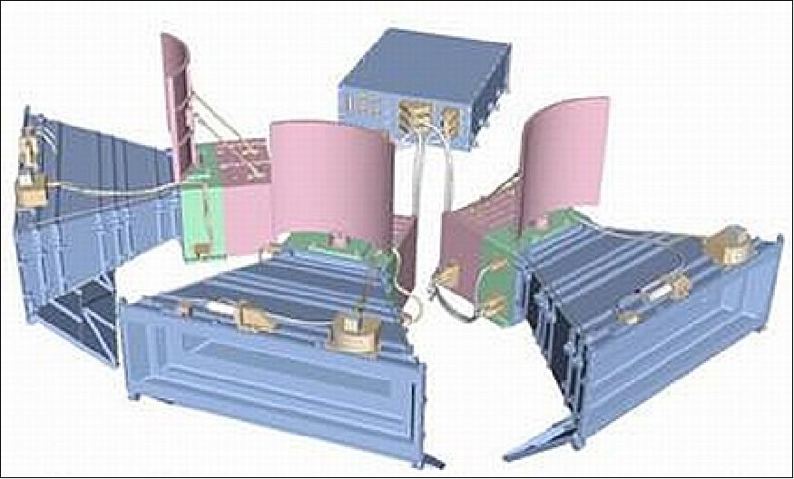
SMEI (Solar Mass Ejection Imager)
SMEI is a proof-of-concept imaging instrument designed and built by an international consortium comprising the US AFRL (Air Force Research Laboratory), the University of Birmingham, UK, the University of California, San Diego (UCSD), Boston College and Boston University. Funding is provided by NASA, AFRL and the University of Birmingham. SMEI is an all-sky camera experiment capable of imaging CMEs (Coronal Mass Ejections) as they propagate from the sun through the solar wind.
The objective is to monitor solar activity (detection of transient clouds of hot ionized gases - referred to as plasma) with the goal of more accurately predicting geomagnetic disturbances as they can have a serious effect on Earth-orbiting satellites, electrical power distribution networks, and long-distance radio communication. SMEI is required to image faint sources against a background that can be two orders of magnitude brighter. A differential photometric precision of about 0.1% is needed to separate the relatively faint emissions from CMEs and other propagating disturbances from the much brighter zodiacal dust cloud and stars. This separation and the necessary subtraction of the stellar contribution also requires accurate angular registration of individual images. The other major sources of background light are scattered sunlight, moonlight and Earth glow. 25) 26) 27) 28)
SMEI is designed to map large-scale variations in heliospheric electron densities from Earth orbit by observing Thomson-scattered sunlight from within the heliospheric volume (monitoring of solar optical radiation which is scattered off the plasma cloud as it moves out from the sun - measurement of the size, shape, speed, frequency, energy flux, mass, and momentum of CMEs). Conceived as an all-sky coronagraph, SMEI views the outward flow of structures in the solar atmosphere. These include CMEs, corotating structures (streamers), and other solar wind density enhancements (or depletions) such as the density variations behind shock waves. 29) 30)
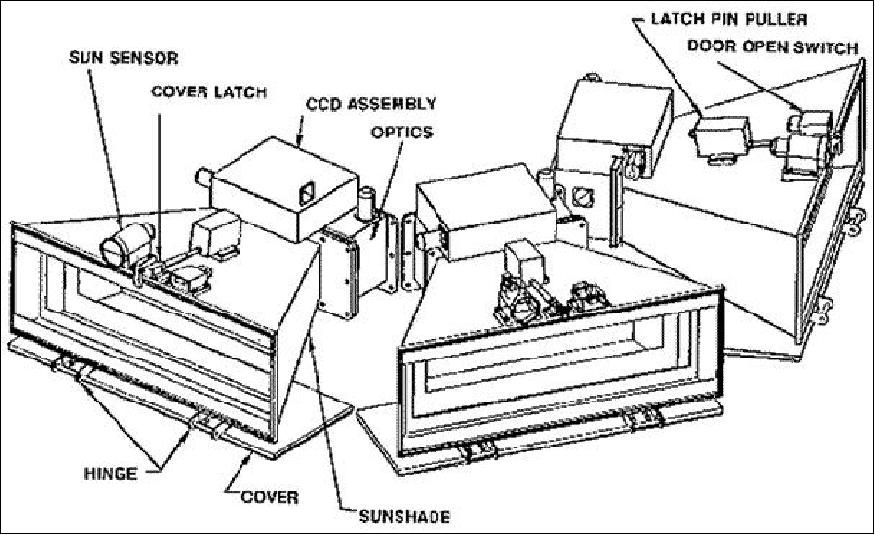
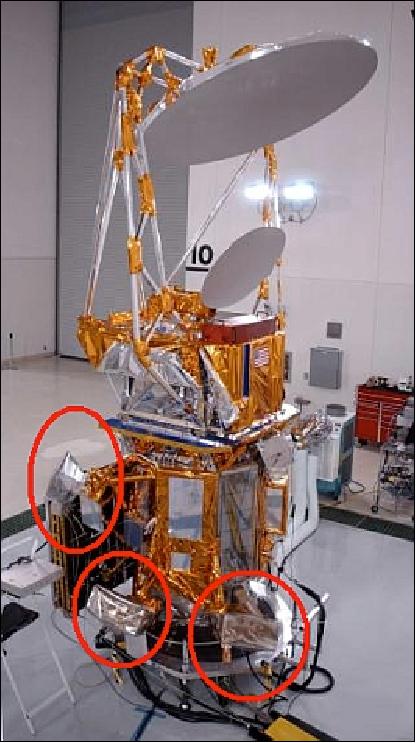
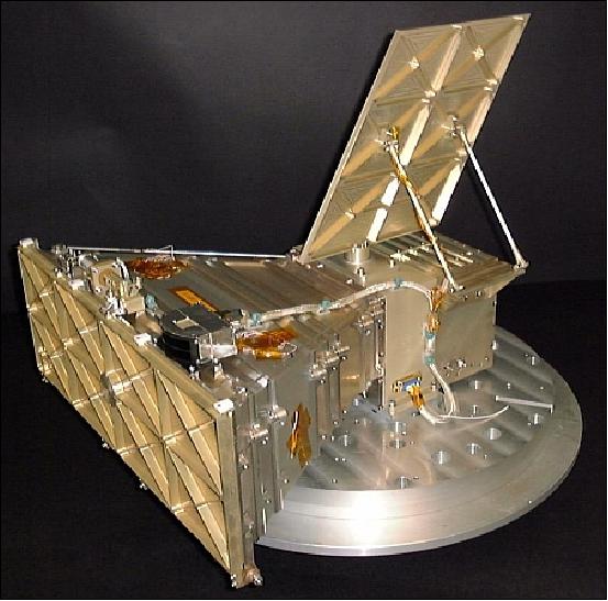
The SMEI instrument consists of three wide-angle CCD cameras each of which has a fan-beam field of view (FOV) of size 3º x 60º. The cameras with their baffles are mounted onto the S/C in such a way that the combined 180º long fan-beam of the three cameras sweeps around the entire sky once per orbit. The baffles reduce the amount of scattered sunlight reaching a camera by about 10 orders of magnitude when it is viewing a region near the sun. The CCDs are cooled to about -35ºC by passive radiators. A common data handling unit (DHU), interfacing to the S/C telemetry and telecommand systems, collects the data from all three cameras and controls their operation (a MIL-STD-1553B bus is used for on-board communications). The DHU includes a powerful processor system which is based around the digital signal processor SMJ320C50 of TI, operating at 19 MIPS making extensive use of field programmable gate arrays. The instrument mass of SMEI is 35 kg.
The flight software controls the data transfer between the cameras, data compression, data transfer from SMEI to the S/C telemetry system, and operational commands to SMEI from the ground. - The SMEI data is used to estimate the outbreak of CMEs (success means that 1-3 day warnings can be given with regard to Earth-intersecting solar shocks, etc.).
After the contribution of stars is removed, SMEI's basic product will be a 100 minute (one orbit) cadence of all-sky maps of heliospheric brightness flux with an angular resolution of about 1º and a photometric precision equivalent to the brightness of a 12th magnitude star.
The SMEI source data rate is 64 kbit/s. The heliospheric images are recorded in broadband white light without filters. The bandpass of the instrument is 450-1100 nm, determined mainly by the CCD response. The basic spatial resolution of the on-board binned pixels is 0.2º. The SMEI data analysis will be able to offer characteristic parameters of CMEs and shocks in the heliosphere (including the mass, energy and momentum fluxes, speed, pressure, shape, etc.), due to the instrument's high spatial and temporal resolution.
As of the fall of 2006, SMEI has seen over 200 CMEs; 30 of which were Earth-directed (halo) CMEs. With this major step of its mission achieved, SMEI is helping scientists to better understand, and predict with longer lead-times, the harmful solar effects on spacecraft and ground systems. 32)
References
1) Peter W. Gaiser, Karen M. St. Germain, Elizabeth M. Twarog, Gene A. Poe, William Purdy, Donald Richardson, Walter Grossmann, W. Linwood Jones, David Spencer, Gerald Golba, Jeffrey Cleveland, Larry Choy, Richard M. Bevilacqua, Paul S. Chang, "The WindSat Spaceborne Polarimetric Microwave Radiometer: Sensor Description and Early Orbit Performance," IEEE Transactions on Geoscience and Remote Sensing, Vol. 42, No 11, Nov. 2004, pp.2347-2361, URL: http://www.nrl.navy.mil/WindSat/pdfs/TGRS04_WindSat_Gaiser.pdf
2) http://www.nrl.navy.mil/WindSat/index.php
3) Note: The NPOESS program is the merged successor program (next generation) of the weather satellite series: POES of NOAA and DMSP of DoD
4) "WindSat homepage," U.S. Naval Research Lab, accessed on 16 January 2019, URL: https://web.archive.org/web/20201114125032/https://www.nrl.navy.mil/WindSat/
5) Barbara Manganis Braun, Sam Myers Sims, James McLeroy, Ben Brining, "Breaking (Space) Barriers for 50 Years: Past, Present, and Future of the DoD Space Test Program," 31st Annual AIAA/USU Conference on Small Satellite, Logan UT, USA, Aug. 5-10, 2017, paper: SSC17-X-02, URL: http://digitalcommons.usu.edu/smallsat/2017/all2017/137/
6) M. H. Bettenhausen, M. D. Anguelova, "An updated geophysical model for WindSat operations," Proceedings of IGARSS 2017 (IEEE International Geoscience and Remote Sensing Symposium), Fort Worth, Texas, USA, July 23–28, 2017
7) http://www.nrl.navy.mil/WindSat/
8) Information provides by Peter Gaiser of NRL
9) John Stubstad, DoD Space S&T Community of Interest — Navy Success Story WindSat/Coriolis," Sept. 30, 2015, URL: http://www.defenseinnovationmarketplace.
mil/resources/Space_ST_CoI_NDU_Brief.pdf
10) Information provides by Peter Gaiser of NRL.
11) Andrew Buffington, Mario M. Bisi, John M. Clover, P. Paul Hick, Bernard V. Jackson, Thomas A. Kuchar, Stephan D. Price, "Measurements of the Gegenschein brightness from the Solar Mass Ejection Imager (SMEI)," Icarus, Volume 203, Issue 1, September 2009, pp. 124-133
12) Janet C. Johnston, Paul E. Holladay, Thomas A. Kuchar, "Solar Mass Ejection Imager (SMEI) Mission: Final Report," Oct. 25, 2007, AFRL-VS-HA-TR-2007-1126, URL: http://www.dtic.mil/dtic/tr/fulltext/u2/a485524.pdf
13) Peter Gaiser, "WindSat Mission Overview and Status," June 5, 2006, URL: http://manati.star.nesdis.noaa.gov/SVW_nextgen/OVW%20
Workshop/Gaiser_WindSat_Miami_05Jun06.ppt
14) Peter Gaiser, "WindSat Spaceborne Polarimetric Microwave Radiometer: Mission Overview," Polar Max 2006, URL: ftp://ftp.ifremer.fr/ifremer/cersat_salinity/exchange/jb/bibliography
_ocean_passive/ocean%20passive%20radiometry
-general/1.8Gaiser_PMax_WindSat_ver1.pdf
15) Information provided by Peter W. Gaiser of NRL, Washington D. C.
16) P. W. Gaiser, "WindSat - Remote Sensing of Ocean Surface Winds," 2004, URL: http://www.nrl.navy.mil/research/nrl-review/2004/featured-research/gaiser/
17) J. T. Johnson, W. H. Theunissen, S. W. Ellingson, "A Study of Sea Emission Models for WindSat," IGARSS 2003, Toulouse, France, July 21-25, 2003
18) K. M. St. Germain, P. W. Gaiser, "Spaceborne polarimetric radiometer and the WindSat Coriolis mission,",Proceedings of the IEEE Aerospace Conference, IEEE Vol. 5, 2000, pp. 159-164,
19) Nai-Yu Wang , P. S. Chang, R. M. Bevilacqua, C. K. Smith, P. W. Gaiser, "WindSat Atmospheric Forward Model Comparisons," Proceedings of IGARSS 2002, Toronto, Canada, June 24-28, 2002
20) W. E. Purdy, P. W. Gaiser, G. A. Poe, E. A. Uliana, T. Meissner, F. J. Wentz, "Geolocation and Pointing Accuracy Analysis for the WindSat Sensor," IEEE Transactions on Geoscience and Remote Sensing, Vol. 44, No 3, March 2006, pp. 496-505
21) W. L. Jones, J. Park, S. Soisuvarn, L. Hong, P. W. Gaiser, K. M. St. Germain, "Deep-Space Calibration of WindSat Radiometer," IEEE Transactions on Geoscience and Remote Sensing, Vol. 44, No 3, March 2006, pp. 476-495
22) W. L. Jones, J. Park, P. W. Gaiser, T. T. Wilheit, "Deep-Space Calibration of WindSat Radiometer," Proceedings of IGARSS 2004, Anchorage, AK, USA, Sept. 20-24, 2004
23) Special Issue (18 papers) on the WindSat Spaceborne Polarimetric Radiometer -Calibration/Validation and Wind Vector Retrieval," IEEE Transactions on Geoscience and Remote Sensing, Vol. 44, No 3, March 2006
24) P. W. Gaiser, E. M. Twarog, Li Li, K. M. St. Germain, G. A. Poe, W. Purdy, Z. Jelenak, P. S. Chang, L. Connor, "The WindSat Space Borne Polarimetric Microwave Radiometer: Sensor Description and Mission Overview," Proceedings of IGARSS 2004, Anchorage, AK, USA, Sept. 20-24, 2004
25) http://www.sr.bham.ac.uk/~mpc/p2/smei/
26) http://smei.ucsd.edu/index.html
27) B. V. Jackson, A. Buffington, P. Hick, S.W. Kahler, S. L. Keil, R. C. Altrock, G. M. Simnett, D. F. Webb, "The Solar Mass Ejection Imager," Phys. Chem. Earth, 22, 441, 1997
28) D. F. Webb, J. C. Johnston, R. R. Radick, "The Solar Mass Ejection Imager (SMEI): A New Tool for Space Weather," EOS Transactions of AGU, Vol. 83, No 4, Jan. 22, 2002, pp. 33-39
29) D. F. Webb, D. R. Mizuno, A. Buffington, M. P. Cooke, C. J. Eyles, C. D. Fry, L. C. Gentile, P. P. Hick, P. E. Holladay, T. A. Howard, J. G. Hewitt, B. V. Jackson, J. C. Johnston, T. A. Kuchar, J. B. Mozer, S. Price, R. R. Radick, G. M. Simnett, S. J. Tappin, "Solar Mass Ejection Imager (SMEI) observations of coronal mass ejections (CMEs) in the heliosphere," Journal of Geophysical Research, Vol. 111, A12101, doi:10.1029/2006JA011655, 2006
30) B. V. Jackson, P: P. Hick, A. Buffington, R. Gold, G. M. Simnett, C. J. Eyles, M. P. Cooke, "SMEI: Design and Development of an Earth-Orbiting All-Sky Coronagraph," Proceedings of SPIE Vol. 5171, 2004, pp. 1-5
31) B. V. Jackson, M. M. Bisi, P. P. Hick, A. Buffington, J. M. Clover, D. F. Webb, "SMEI Observations of the Heliosphere During WHI," URL: http://ihy.boulder.swri.edu/WHI/AGUMAY08/POSTERS/Jackson_SMEI.pdf
32) "AFRL Solar Mass Ejection Imager New Tool for Space Weather," URL: http://www.kirtland.af.mil/shared/media/document/AFD-070404-102.pdf
Spacecraft Launch Mission Status Sensor Complement References Back to Top