Copernicus: Sentinel-2
EO
ESA
Atmosphere
Ocean
Sentinel-2 is a constellation of two optical imaging satellites, which are a part of Copernicus - the European Union’s Earth observation program. Three identical satellites comprise the Sentinel-2 constellation: Sentinel-2A (launched 2015), Sentinel-2B (2017), and Sentinel-2C (2024). The orbits of two satellites are coordinated to optimise coverage and revisit time.
Quick facts
Overview
| Mission type | EO |
| Agency | ESA, COM |
| Mission status | Operational (nominal) |
| Launch date | 23 Jun 2015 |
| Measurement domain | Atmosphere, Ocean, Land |
| Measurement category | Multi-purpose imagery (ocean), Radiation budget, Multi-purpose imagery (land), Vegetation, Albedo and reflectance |
| Measurement detailed | Ocean imagery and water leaving spectral radiance, Land surface imagery, Vegetation type, Fire fractional cover, Earth surface albedo, Leaf Area Index (LAI), Land cover, Normalized Differential Vegetation Index (NDVI), Photosynthetically Active Radiation (PAR), Fraction of Absorbed PAR (FAPAR), Soil type, Upwelling (Outgoing) spectral radiance at TOA |
| Instruments | MSI (Sentinel-2) |
| Instrument type | High resolution optical imagers |
| CEOS EO Handbook | See Copernicus: Sentinel-2 summary |
Related Resources
Summary
Mission Capabilities
Data products from Sentinel-2 satellites are used for a wide variety of applications, including precision farming, water quality monitoring, natural disaster management and methane emission detection. Sentinel-2 provides particularly useful information for monitoring natural ecosystems, as it can differentiate between vegetation types and measure biophysical variables such as leaf area index, leaf chlorophyll content, and leaf water content.
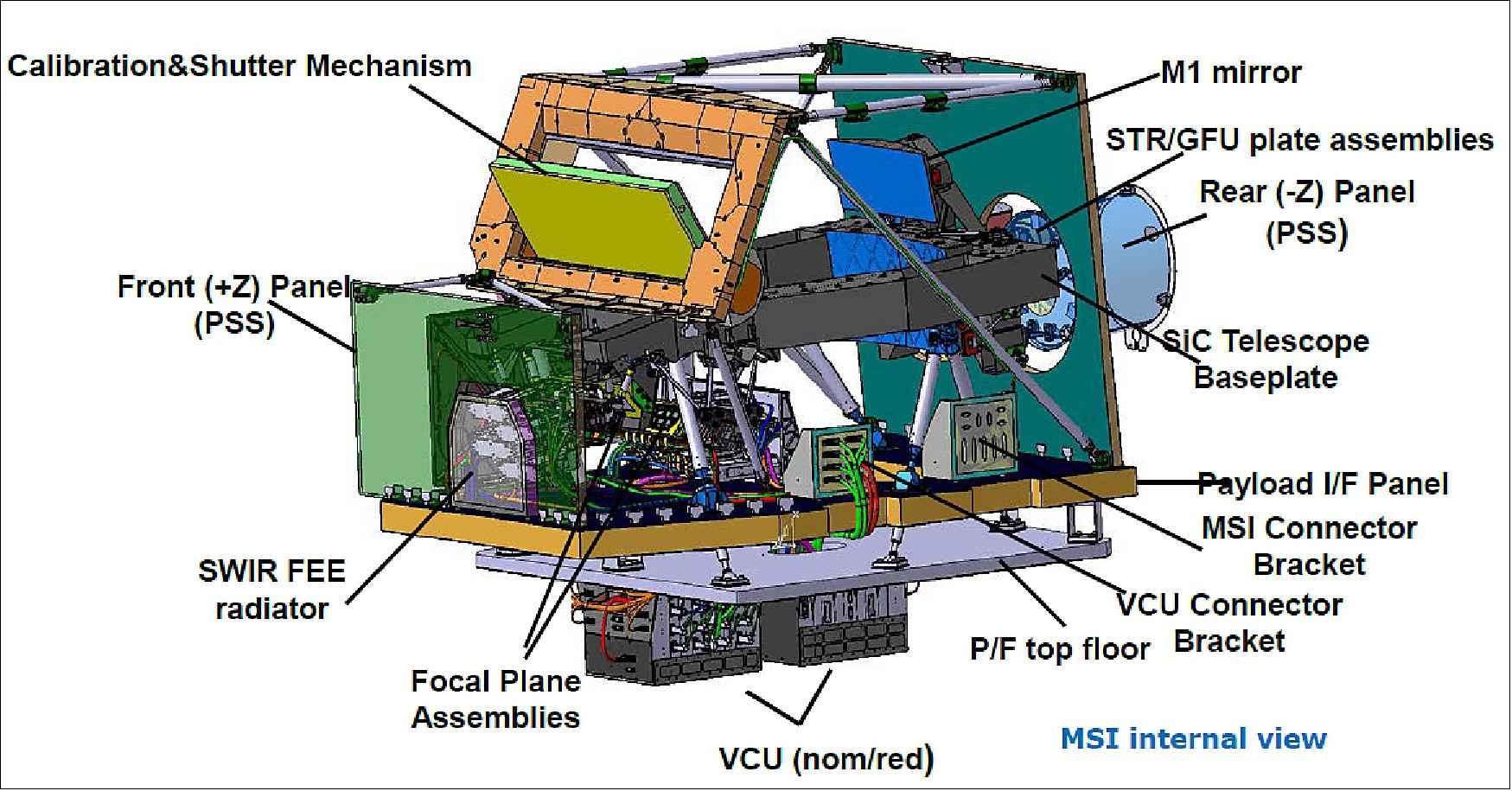
The Sentinel-2 satellites are identical and have a Multispectral Instrument (MSI) onboard. This instrument comprises a three-mirror anastigmat (TMA) telescope to collect and focus light, a beam splitter to separate visible and near-infrared (VNIR) from short-wave infrared (SWIR) light, two focal planes with 12 detectors on each for the two different radiation types, a diffuser for radiometric calibration, and a calibration and shutter mechanism (CSM) to protect the instrument from sunlight at launch.
Performance Specifications
MSI has 13 spectral bands: four visible bands (one at 60 m resolution and three at 10 m resolution); five near-infrared (NIR) bands (one at 10 m resolution and four at 20 m resolution); two shortwave infrared (SWIR) bands at 20 m resolution; and two additional bands—one for water vapor detection and one for cirrus detection—both with a 60 m resolution.
The Sentinel-2 satellites have a swath width of 290 km, and together achieve a five-day revisit time. The two satellites follow the same sun-synchronous orbit with an inclination of 98.6° but are 180° out of phase. They orbit at an altitude of 786 km with a period of 101 minutes.
Space and Hardware Components
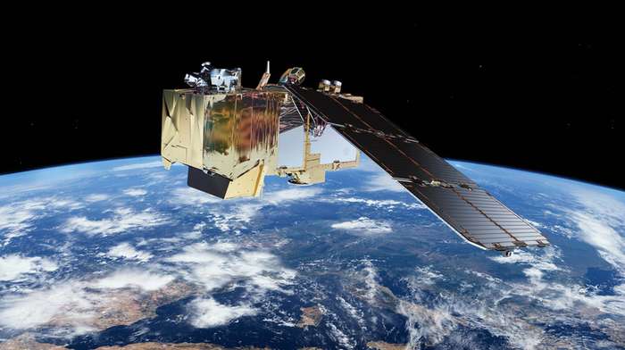
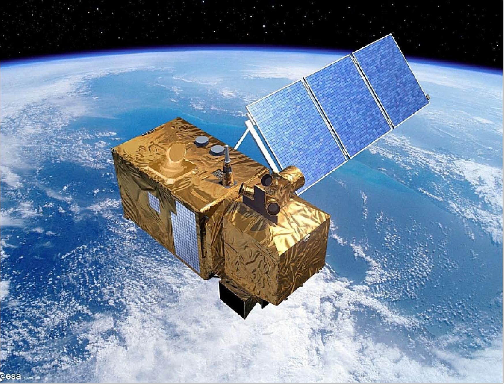
Sentinel-2 uses the AstroBus-L of Airbus Defence & Space, a Low Earth Orbit (LEO) optimised platform, providing stability and power for the mission's imaging equipment and communications systems. The total mass of Sentinel-2 is approximately 1,200 kg. The platform provides X-band MSI data downlink at 560 Mbit/s and telemetry, tracking, and command (TT&C) data link with 64 kbit/s uplink and 2 Mbit/s downlink.
Overview
Sentinel-2 is a multispectral operational imaging mission within the European Union's Copernicus Programme, jointly implemented by the EC (European Commission) and ESA (European Space Agency) for global land observation at high resolution and revisit capability to provide enhanced continuity of data. Sentinel-2 data covers vegetation, soil and water cover for land, inland and coastal waters, as well as cloud screening and atmospheric corrections. 1) 2) 3) 4) 5) 6) 7) 8)
To meet user needs, the Sentinel-2 satellite data supports the operational generation of the following high-level products:
• Generic land cover, land use and change detection maps (e.g. CORINE land cover maps update, soil sealing maps, forest area maps)
• Maps of geophysical variables (e.g. leaf area index, leaf chlorophyll content, leaf water content).
The mission is dedicated to the full and systematic coverage of land surface (including major islands) globally with the objective to provide cloud-free products typically every 15 to 30 days over Europe and Africa. This objective is achieved thanks to the 5-day geometric revisit time of the constellation of two operational satellites.
The following list summarises the top-level system design specifications derived from the user requirements as defined by the GMES (Global Monitoring for Environment and Security) program (now known as Copernicus):
• Sentinel-2 will provide continuity of data for services initiated within the GSE (GMES Service Element) projects. It will establish a key European data source for the GMES Land Fast Track Monitoring Services and contribute to the GMES Risk Fast Track Services.
• The frequent revisit and high mission availability goals call for 2 satellites in orbit at a time, each with a 290 km wide swath using a single imaging instrument
• Continuous land + islands carpet mapping imaging within the latitude range of -56º to +83º (the selected orbit excludes imagery from Antarctica)
• 10 m, 20 m, and 60 m spatial resolution (in the VNIR to SWIR spectral range) to identify spatial details consistent with 1 ha MMU (Minimum Mapping Unit)
• An accurate geolocation (< 20 m) of the data is required (without GCPs) and shall be produced automatically to meet the timeliness requirements. The geolocation accuracy of Level 1 b imagery data w.r.t. WGS-84 (World Geodetic System - 1984) reference Earth ellipsoid of better than 20 m at 2σ confidence level without the need of any ground control points.
• Very good radiometric image quality (combination of onboard absolute and on-ground vicarious calibration).
• The mission lifetime is specified as 7.25 years and propellant is to be sized for 12 years, including provision for de-orbiting manoeuvres at end-of-life.
• 2 weeks of satellite autonomy and maximum decoupling between flight operations and mission exploitation
To provide operational services over a long period (at least 15 years following the launch of the first satellites), four satellites will be developed, with nominally two satellites in operation in orbit and a third one stored on the ground as a backup.
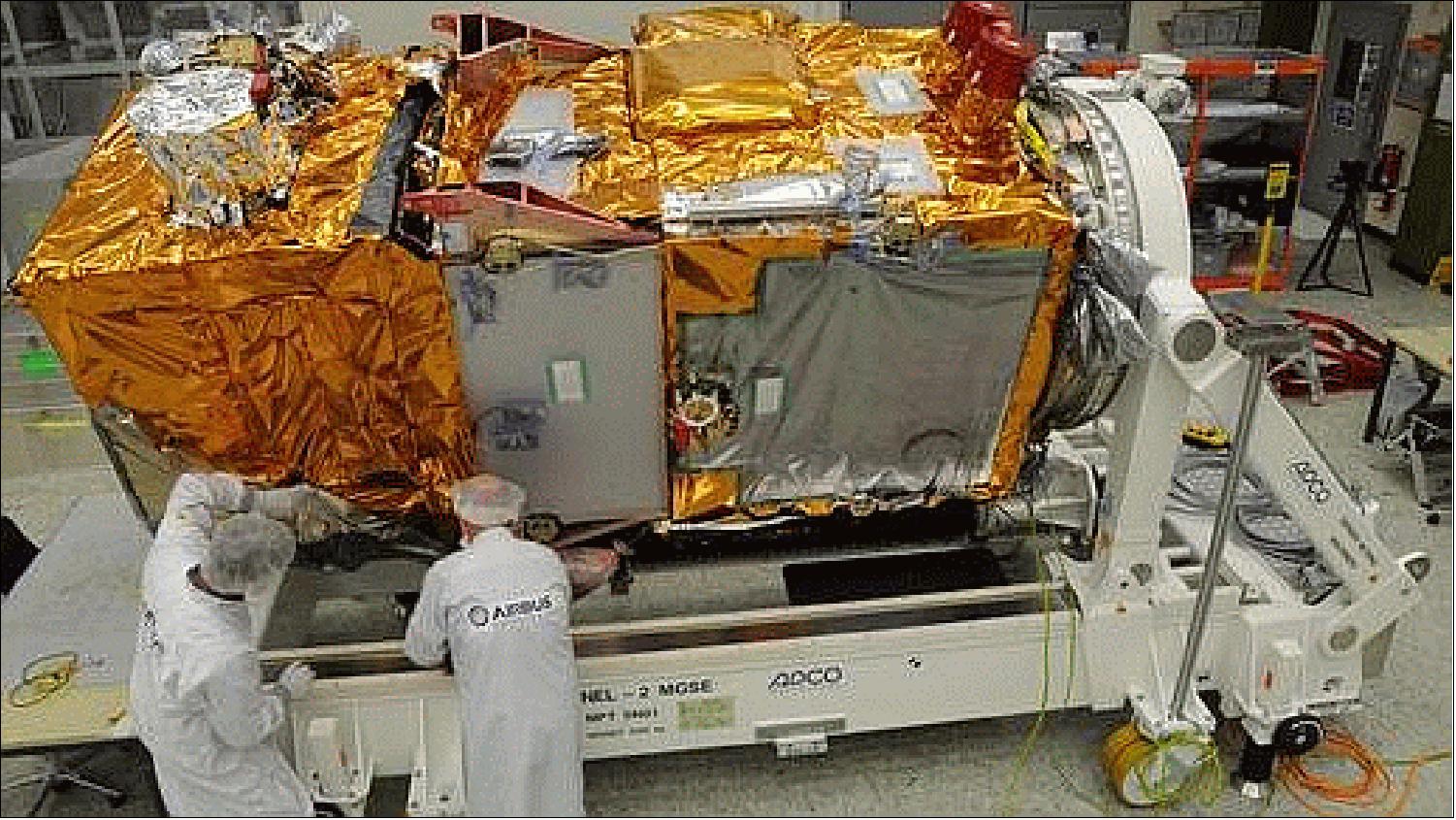
In partnership: The Sentinel-2 mission has been made possible thanks to the close collaboration between ESA, the European Commission, industry, service providers and data users. Demonstrating Europe’s technological excellence, its development has involved around 60 companies, led by Airbus Defence and Space in Germany for the satellites and Airbus Defence and Space in France for the multispectral instruments. 10)
The mission has been supported in kind by the French space agency CNES to provide expertise in image processing and calibration, and by the German Aerospace Center DLR which provides the optical communication payload, developed by Tesat Spacecom GmbH. This piece of technology allows the Sentinel-2 satellites to transmit data via laser to satellites in geostationary orbit carrying the European Data Relay System (EDRS). This new space data highway allows large volumes of data to be relayed very quickly so that information can be even more readily available to users.
Developing Sentinel-2 has involved a number of technical challenges, from early specification in 2007 to qualification and acceptance in 2015. The satellite requires excellent pointing accuracy and stability and, therefore, high-end orbit and attitude control sensors and actuators. The multispectral imager is the most advanced of its kind, integrating two large visible near-infrared and shortwave infrared focal planes, each equipped with 12 detectors and integrating 450,000 pixels. The instrument’s optomechanical, geometric, and radiometric stability must be extremely high, to avoid image distortion and stray light effects.
Each satellite has a high level of autonomy so that it can operate without any intervention from the ground for periods of up to 15 days. This requires sophisticated autonomous failure analysis, detection and correction on board.
The ‘carpet mapping’ imaging plan requires the acquisition, storage and transmission of 1.6 TB of data per orbit. This massive data blast results from the combination of the 290 km swath with 13 spectral channels at a spatial resolution as high as 10 m.
Land in focus
Ensuring that land is used sustainably, while meeting the food and wood demands of a growing global population is one of today’s biggest challenges. The Copernicus land service provides information to help respond to global issues such as this as well as focusing on local matters, or ‘hotspots’, that are prone to specific challenges.
Sentinel-2 can distinguish between different crop types and delivers timely data on plant indices such as leaf area index, leaf chlorophyll content and leaf water content – all of which are essential to accurately monitor plant growth. This kind of information is essential for precision farming: helping farmers decide how best to nurture their crops and predict their yield.
Alongside economic benefits, this information supports food security in developing countries. The mission’s revisit time of just five days, along with the mission’s range of spectral bands, means that changes in plant health and growth status can be easily monitored.Sentinel-2 also provides information about changes in land cover, for example due to urban growth, deforestation, and disasters.The Copernicus land service addresses five ‘pan-European’ themes covering 39 countries, including sealed soil (imperviousness), tree cover density, forest type, and grasslands.
The mission also provides information for bathymetry, as well as for monitoring coral reefs and pollution in lakes and coastal waters at high spatial resolution with frequent coverage. The capacity for frequent coverage highlights Sentinel-2’s ability to contribute to disaster mapping and humanitarian aid work.
Sentinel-2A launch | June 23, 2015, by Vega from Kourou, French Guiana |
Sentinel-2B launch | March 2017, by Vega from Kourou, French Guiana |
Sentinel-2C launch | September 4, 2024, by Vega from Kourou, French Guiana |
Orbit | Sun-synchronous at altitude 786 km, Mean Local Solar Time at descending node: 10:30 (optimum Sun illumination for image acquisition) |
Geometric revisit time | Five days from two-satellite constellation (at equator) |
Design life | Seven years (carries consumable for 12 years: 123 kg of fuel including end of life deorbiting) |
MSI (Multispectral Imager) | MSI covering 13 spectral bands (443–2190 nm), with a swath width of 290 km and a spatial resolution of 10 m (four visible and near-infrared bands), 20 m (six red edge and shortwave infrared bands) and 60 m (three atmospheric correction bands). |
Receiving stations | MSI data: transmitted via X-band to core Sentinel ground stations and via laser link through EDRS. |
Main applications | Agriculture, forests, land-use change, land-cover change. Mapping biophysical variables such as leaf chlorophyll content, leaf water content, leaf and area index; monitoring coastal and inland waters; risk and disaster mapping |
Mission | Managed, developed, operated and exploited by various ESA establishments |
Funding | ESA Member States and the European Union |
Prime contractors | Airbus Defence & Space Germany for the satellite, Airbus Defence & Space France for the instrument |
Cooperation | CNES: Image quality optimization during in-orbit commissioning |
Table 1: Sentinel-2 mission overview and key specifications
Spacecraft
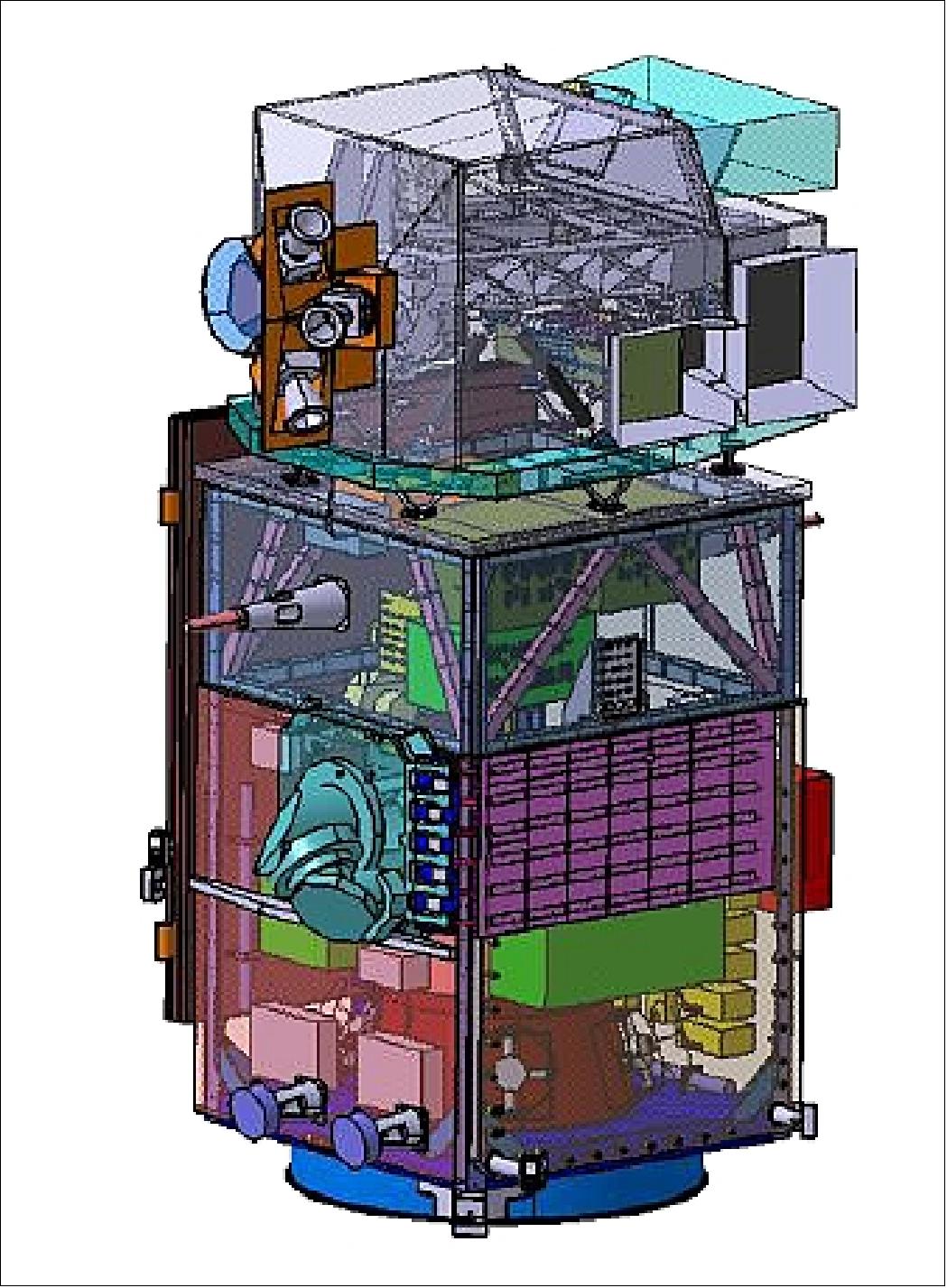
In April 2008, ESA awarded the prime contract to Airbus Defence and Space (former EADS-Astrium GmbH) of Friedrichshafen, Germany to provide the first Sentinel-2A Earth observation satellite. In the Sentinel-2 mission program, Astrium is responsible for the satellite’s system design and platform, as well as for satellite integration and testing. Astrium Toulouse supply MSI (MultiSpectral Instrument), and Astrium Spain is in charge of the satellite’s structure pre-integrated with its thermal equipment and harness. The industrial core team also comprises Jena Optronik (Germany), Boostec (France), Sener and GMV (Spain). 11) 12) 13) 14)
Sentinel-2 uses the AstroBus-L of EADS Astrium. It is a standard modular ECSS (European Cooperation for Space Standards) satellite platform compatible with an in-orbit lifetime of up to 10 years, with consumables sizeable according to the mission needs. The platform design is one-failure tolerant and the standard equipment selection is based on minimum Class 2 EEE parts, with compatibility to Class 1 in most cases.
The AstroBus-L platform is designed for direct injection into LEO (Low Earth Orbit). Depending on the selection of standard design options, AstroBus-L can operate in a variety of LEOs at different heights and with different inclinations. An essential feature of AstroBus-L is the robust standard FDIR (Failure Detection, Isolation and Recovery) concept, which is hierarchically structured and can easily be adapted to specific mission needs.
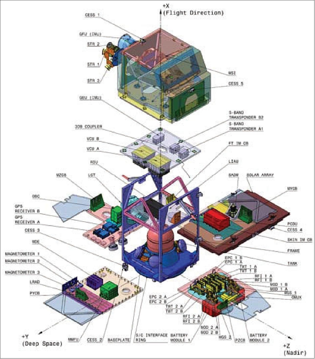
The satellite is controlled in 3-axes via high-rate multi-head star trackers, mounted on the camera structure for better pointing accuracy and stability, gyroscopes, and a GNSS receiver assembly. The AOCS (Attitude and Orbit Control Subsystem) comprises the following elements: 18)
• A dual-frequency GPS receiver (L1/L2 code) for position and time information
• A STR (Star Tracker) assembly for precise attitude information (use of 3 STRs)
• A RMU (Rate Measurement Unit) for rate damping and yaw acquisition purposes
• A redundant precision IMU (Inertial Measurement Unit) for high-accuracy attitude determination
• Magnetometers (MAG) for Earth magnetic field information
• CESS (Coarse Earth Sun Sensors) for coarse Earth and Sun direction determination
• 4 RW (Reaction Wheels) and 3 MTQ (Magnetic Torquers)
• RCS (Reaction Control System) a monopropellant propulsion system for orbit maintenance with 1 N thrusters
The different tasks of the AOCS are defined by the following modes:
• Initial Acquisition and Save Mode (rate damping, Earth acquisition, yaw acquisition, steady-state)
• Normal Mode (nominal and extended observation)
• Orbit Control Mode (in- and out-of-plane ΔV manoeuvres).
The geolocation accuracy requirements of < 20 m for the imagery translate into the following AOCS performance requirements as stated in Table 2.
Attitude determination error (onboard knowledge) | ≤ 10 µrad (2σ) per axis |
AOCS control error | ≤ 1200 µrad (3σ) per axis |
Relative pointing error | ≤ 0.03 µrad/1.5 ms (3σ); and ≤ 0.06 µrad/3.0 ms (3σ) |
Table 2: AOCS performance requirements in normal mode
For Sentinel-2 it was decided to mount both the IMU and the star trackers on the thermally controlled sensor plate on the MSI. So the impact of time-variant IMU/STR misalignment on attitude performance can be decreased to an absolute minimum. Furthermore, the consideration of the time-correlated star tracker noises by covariance tuning was decided.
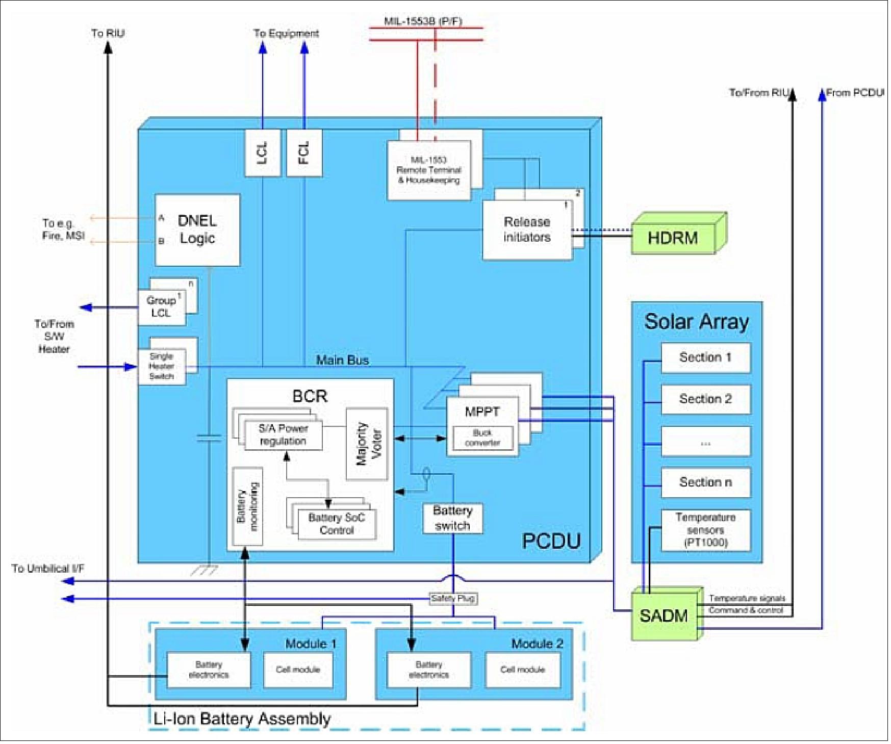
The EPS (Electric Power Subsystem) consists of:
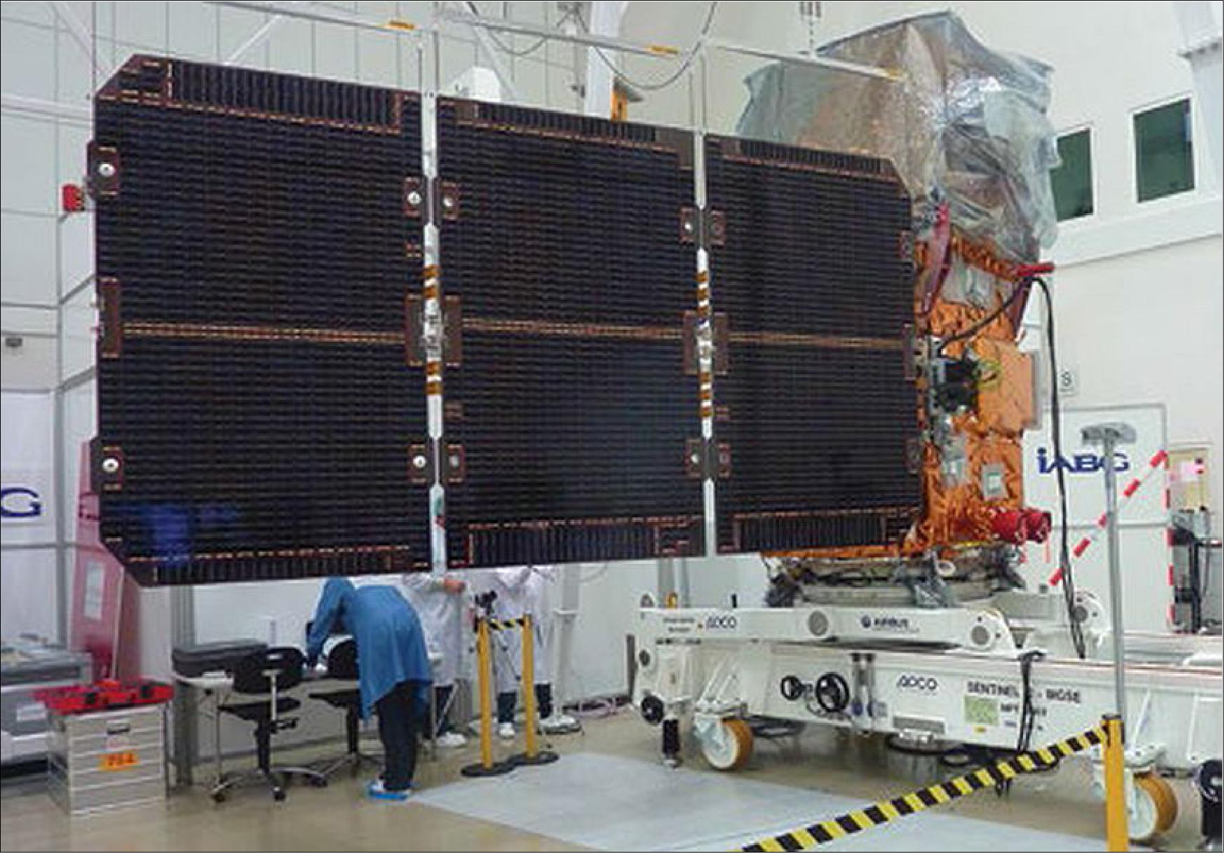
• Solar Array (one deployable and rotatable single wing with three panels). Total array area of 7.1 m2. Use of 2016 triple junction GaAs solar cells with integrated diodes. Total power of 2300 W (BOL) and 1730 W (EOL). The mass is < 40 kg.
• SADM (Solar Array Drive Mechanism) for array articulation. Use of a two two-phase stepper motor with µ-stepping to minimise parasitic distortions during MSI operation, motor step angle 1.5º. Mass of < 3.2 kg.
• PCDU (Power Control and Distribution Unit). PCDU with one unregulated 28 V ±4 V main power bus. Mass of < 21.6 kg; the in-orbit life is 12.25 years.
• Li-ion batteries with 8 cells in series. The total capacity of 102 Ah @ EOL. Mass = 51 kg.
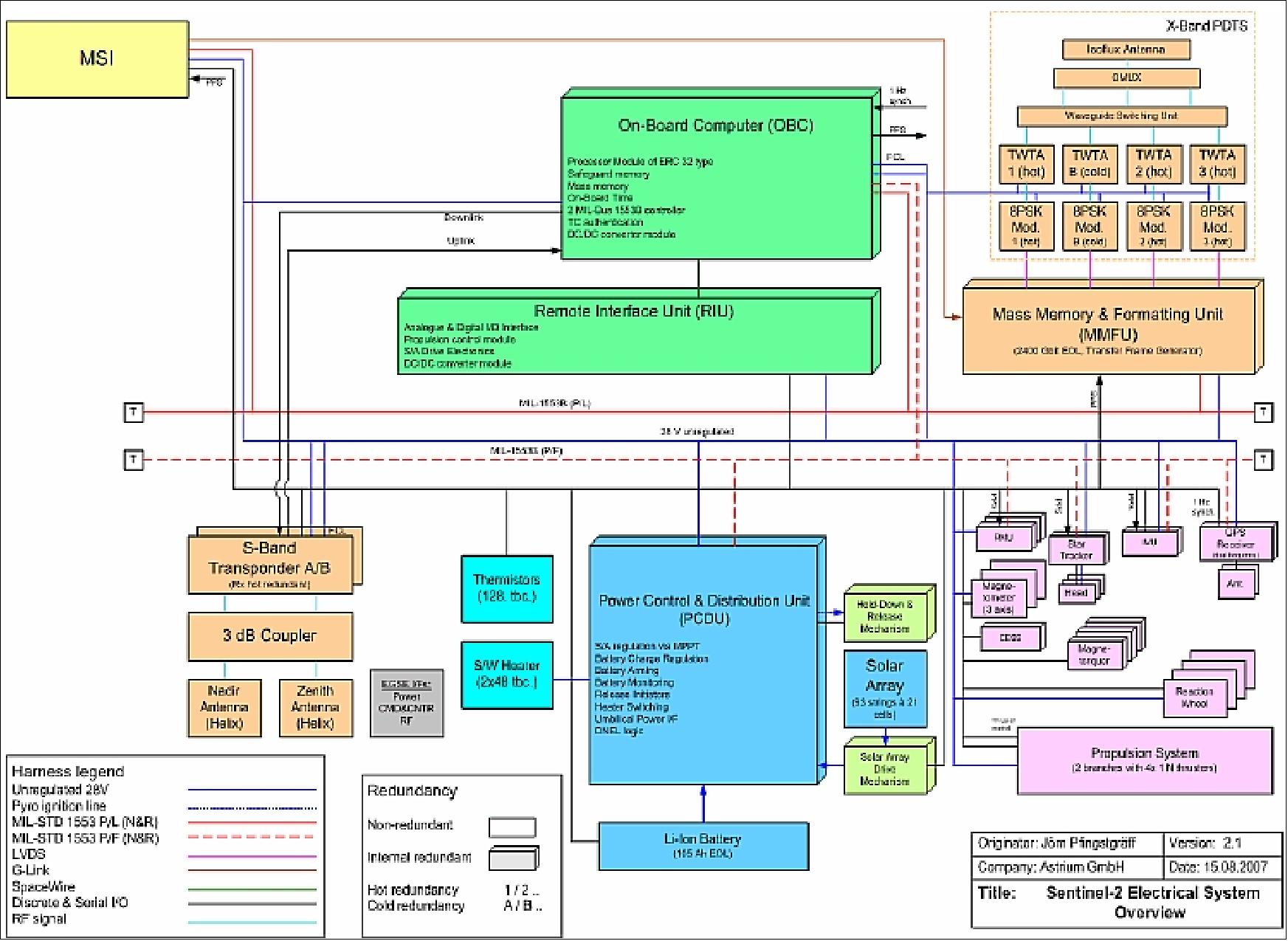
The OBC is based on the ERC32 PM (Processor Module) architecture. The PLDHS (Payload Data Handling System) provides source data compression from 1.3 Gbit/s to 450 Mbit/s [state-of-the-art lossy compression (wavelet transform)].
The spacecraft mass is ~ 1200 kg, including 275 kg for the MSI instrument, 35 kg for the IR payload (optional) and 80 kg propellant (hydrazine). The S/C power is 1250 W max, including 170 W for the MSI and < 100 W for the IR payload. The spacecraft is designed for a design life of 7.25 years with propellant for 12 years of operations, including deorbiting at EOL (End of Life).
Spacecraft mass, power | ~1200 kg, 1700 W |
Hydrazine propulsion system | 120 kg hydrazine (including provision for safe mode, debris avoidance and EOL orbit decrease for faster re-entry) |
Spacecraft design life | 7 years with propellant for 12 years of operations |
AOCS (Attitude and Orbit Control Subsystem) | - 3-axis stabilised based on multi-head Star Tracker and fibre optic gyro - Accurate geo-location (20 m without Ground Control Points) |
RF communications | X-band payload data downlink at 560 Mbit/s |
Onboard data storage | 2.4 Tbit, and data formatting unit (NAND-flash technology as baseline) that supplies the mission data frames to the communication subsystems. |
Optical communications | LCT (Laser Communication Terminal) link is provided via EDRS (European Data Relay Satellite) |
Table 3: Overview of some spacecraft parameters
Payload data are stored in NAND flash memory technology SSR (Solid State Recorder) based on integrated CoReCi (Compression Recording and Ciphering) units of Airbus DS.
The CoReCi is an integrated image compressor, mass memory and data ciphering unit designed to process, store and format multi-spectral video instrument data for the satellite downlink. 19) 20)
The MRCPB (Multi-Résolution par Codage de Plans Binaires) compression algorithm used is a wavelet transform with bit plane coding (similar to JPEG 2000). This complex algorithm is implemented in a dedicated ASIC, with speeds of up to 25 Mpixel/s. Alternatively, this unit can be supplied with a CCSDS compression algorithm using a new ASIC developed with ESA support. The ciphering is based on the AES algorithm with 128-bit keys. The modularity of the design allows the memory capacity and data rate to be adapted by adjusting the number of compressor and memory boards used.
Mission Status
• September 17, 2024: Sentinel-2C delivers first light imagery from around the globe, which were processed by the Copernicus Ground Segment. Initial observation locations included Seville, Spain; the coastline between Southern France and Barcelona; Los Angeles, United States; and Belize. 98)
• September 5, 2024: Sentinel-2C successfully launched onboard a Vega rocket from the European spaceport in Kourou, French Guiana. The rocket launched at 03:50 CEST (4 September 22:50 local time) and the satellite separated at approximately 04:48 CEST. Around 14 minutes later, at 05:02 CEST, ESA received the all-important signal indicating that the satellite was safely in orbit.
This marked the 22nd and final flight of the Vega rocket, which is being phased out in favour of the newer Vega-C. 97)
• August 29, 2024: Sentinel-2C is being readied for launch, and mating to the launch adapater. 95)

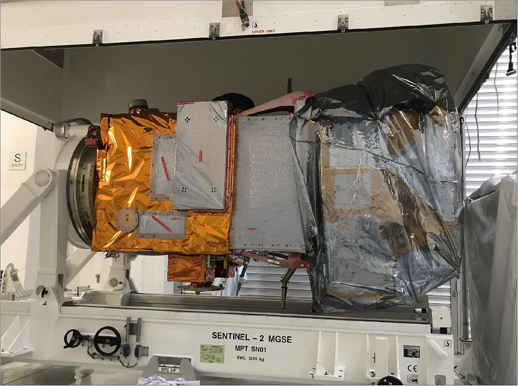
• July 22, 2024: The Sentinel-2C satellite, the third Copernicus Sentinel-2 satellite, has arrived at the European spaceport in French Guiana for liftoff on the final Vega rocket. Once in orbit, Sentinel-2C will replace its predecessor, Sentinel-2A, while Sentinel-2D will later replace Sentinel-2B. 94)
• August 9, 2021: Engineers at Airbus Defence and Space in Friedrichshafen, Germany, have now transported the Sentinel-2C satellite to IABG’s facilities in Ottobrunn for a series of exhaustive tests that will run until the end of 2021. The program includes tests that simulate noise and vibrations of liftoff, as well as the extreme temperature swings it will experience in space. It also includes tests that check correct deployment of the solar wing and electromagnetic compatibility tests in this environment.
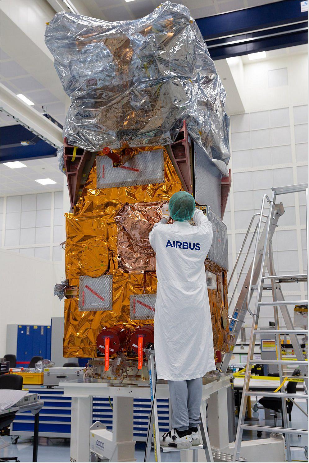
• July 29, 2021: Airbus has finished the integration of the Copernicus Sentinel-2C satellite. It is the third of its kind and will now be shipped to Munich to undergo extensive environmental tests to prove its readiness for space. The test campaign will last until March 2022. 22)
From an altitude of 786 km, the 1.1 ton “C” satellite will enable the continuation of imaging in 13 spectral bands with a resolution of 10, 20 or 60 m and a uniquely large swath width of 290 km. Each Sentinel-2 satellite collects 1.5 TB/day, after onboard compression. The two identical satellites are flying in the same orbit but 180° apart for optimal coverage and revisit time. The satellites orbit the Earth every 100 minutes covering all of Earth’s land surfaces, large islands, and inland and coastal waters every five days.
• February 27, 2017: The ninth Vega light-lift launcher is now complete at the Spaceport, with its Sentinel-2B Earth observation satellite installed atop the four-stage vehicle in preparation for a March 6 mission from French Guiana. 23)
• January 12, 2017: Sentinel-2B arrived at Europe’s spaceport in Kourou, French Guiana on 6 January 2017 to be prepared for launch. After being moved to the cleanroom and left for a couple of days to acclimatise, cranes were used to open the container and unveil the satellite. Over the next seven weeks the satellite will be tested and prepared for liftoff on a Vega rocket. 24)
• November 15, 2016: Sentinel-2B has successfully finished its test program at ESA/ESTEC in Noordwijk, The Netherlands. The second Sentinel-2 Airbus built satellite will now be readied for shipment to the Kourou spaceport in French Guiana begin January 2017. It is scheduled for an early March 2017 lift-off on Vega. 25)
• June 15, 2016: Airbus DS completed the manufacture of the Sentinel-2B optical satellite; the spacecraft is ready for environmental testing at ESA/ESTEC. The Sentinel-1 and -2 satellites are equipped with the Tesat-Spacecom’s LCT (Laser Communication Terminal). The SpaceDataHighway is being implemented within a Public-Private Partnership between ESA and Airbus Defence and Space.
• April 27, 2015: The Sentinel-2A satellite on Arianespace’s next Vega mission is being readied for pre-launch checkout at the Spaceport, which will enable this European Earth observation platform to be orbited in June from French Guiana. With Sentinel-2A now connected to its ground support equipment and successfully switched on, the satellite will undergo verifications and final preparations for a scheduled June 11 liftoff. 27)
• April 23, 2015: The Sentinel-2A satellite has arrived safe and sound in French Guiana for launch in June. The huge Antonov cargo aircraft that carried the Sentinel-2A from Germany, touched down at Cayenne airport in the early morning of 21 April. 28)
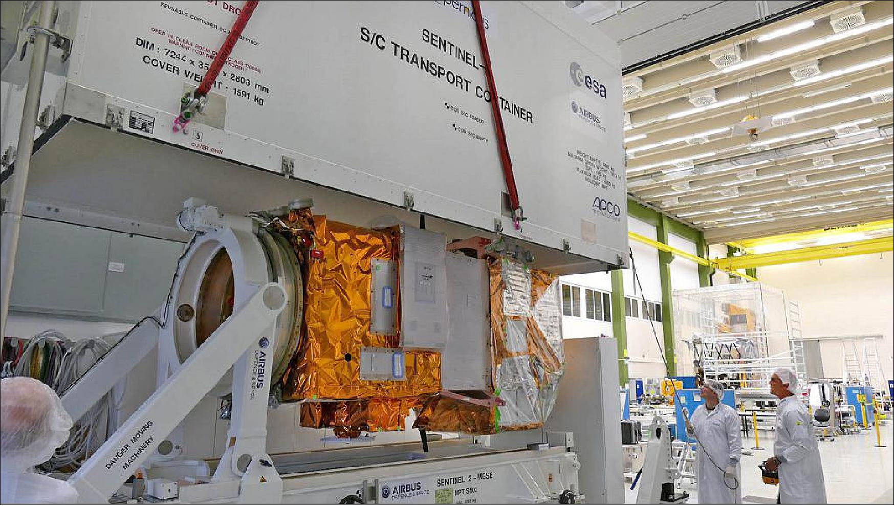
• April 8, 2015: The Sentinel-2A satellite is now being carefully packed away in a special container that will keep it safe during its journey to the Sentinel 2 launch site in French Guiana. The satellite will have one final test, a ‘leak test’, in the container to ensure the propulsion system is tight. Bound for Europe’s Spaceport in French Guiana, Sentinel-2A will leave Munich aboard an Antonov cargo plane on 20 April. Once unloaded and unpacked, it will spend the following weeks being prepared for liftoff on a Vega rocket. 29)
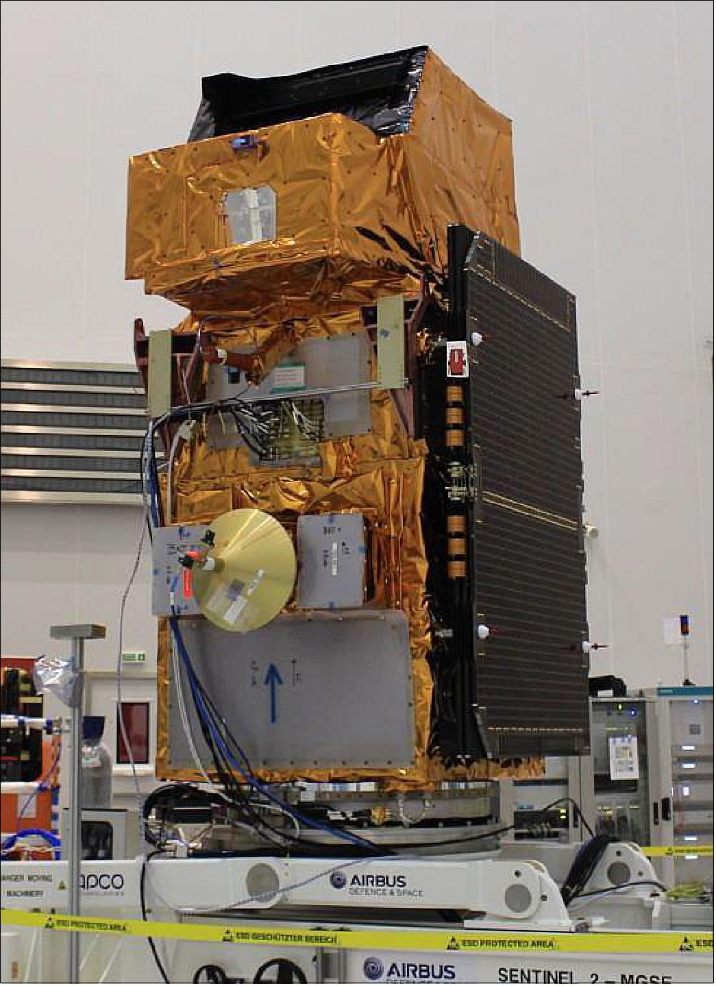
• February 24, 2015: Sentinel-2A is fully integrated at IABG’s facilities in Ottobrunn, Germany before being packed up and shipped to French Guiana for a scheduled launch in June 2015. 30)
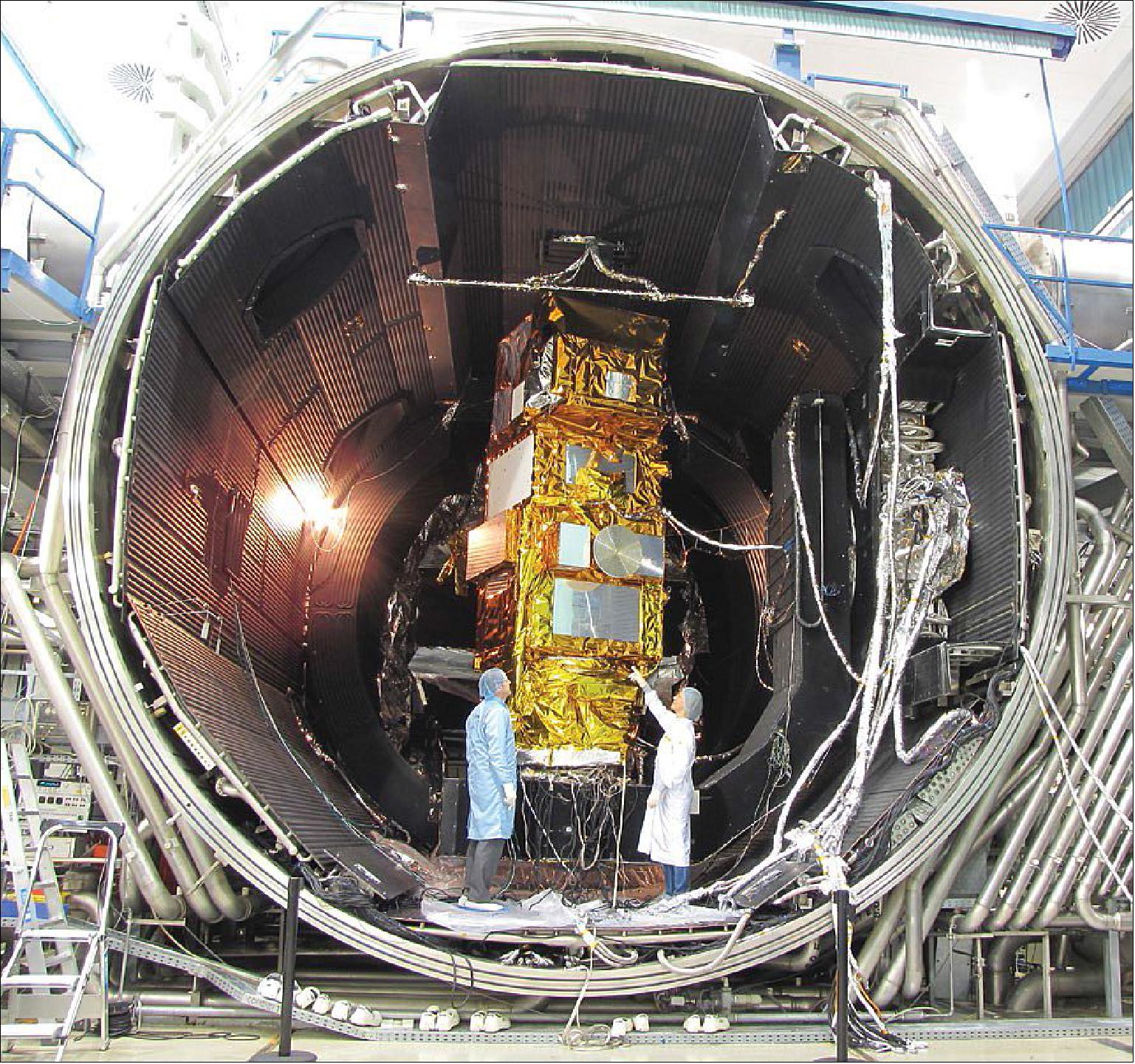
• August 2014: Airbus Defence and Space delivered the Sentinel-2A environmental monitoring satellite for testing . In the coming months, the Sentinel-2A satellite will undergo a series of environmental tests at IABG, Ottobrunn, Germany, to determine its suitability for use in space. 31) 32)
• Sentinel-2 imagery in the period 2022
• Sentinel-2 imagery in the period 2021
• Sentinel-2 imagery in the period 2020
• Sentinel-2 imagery in the period 2019
Launch
| Satellite | Launch Date | Launch Vehicle | Spaceport |
| Sentinel-1A | 23 June, 2015, 1:51:58 UTC | Vega | European Spaceport, Kourou, French Guiana |
| Sentinel-1B | March 7, 2017, 01:49:24 UTC | Vega | European Spaceport, Kourou, French Guiana |
| Sentinel-1C | September 5, 2024, 01:50 UTC | Vega | European Spaceport, Kourou, French Guiana |
Orbit
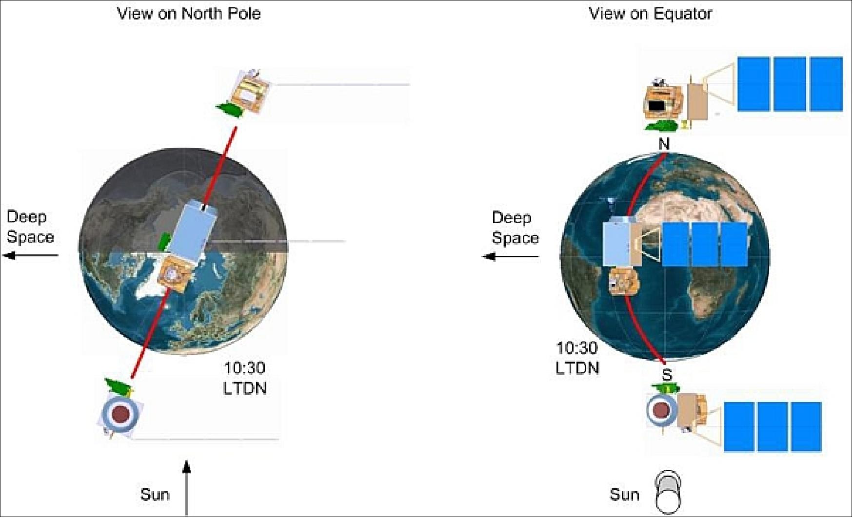
All Sentinel-2 satellites operate in a sun-synchronous orbit at an altitude of 786 km, inclination of 98.5º, period of 101 minutes, and 10:30 hours LTDN (Local Time at Descending Node). This local time has been selected as the best compromise between cloud cover minimization and sun illumination.
The orbit is fully consistent with SPOT and very close to the Landsat local time, allowing seamless combination of Sentinel-2 data with historical data from legacy missions to build long-term temporal series. The two operating Sentinel-2 satellites are equally spaced (180º phasing) in the same orbital plane for a 5 day revisit cycle at the equator.
The Sentinel-2 satellites systematically acquire observations over land and coastal areas from -56° to 84° latitude including islands larger than 100 km2, EU islands, all other islands less than 20 km from the coastline, the whole Mediterranean Sea, all inland water bodies and closed seas. Over specific calibration sites, for example DOME-C in Antarctica, additional observations are made.
Sensor Complement
MSI (Multispectral Imager)
The instrument is based on the pushbroom observation concept. The telescope features a TMA (Three Mirror Anastigmat) design with a pupil diameter of 150 mm, providing a very good imaging quality all across its wide FOV (Field of View). The equivalent swath width is 290 km. The telescope structure and the mirrors are made of silicon carbide (SiC) which allows to minimise thermoelastic deformations. The VNIR focal plane is based on monolithic CMOS (Complementary Metal Oxide Semiconductor) detectors while the SWIR focal plane is based on a MCT (Mercury Cadmium Telluride) detector hybridised on a CMOS read-out circuit. A dichroic beamsplitter provides the spectral separation of VNIR and SWIR channels. 42) 43) 44) 45) 46) 47) 48)
Airbus DS (former EADS Astrium SAS) of Toulouse is prime for the MSI instrument. The industrial core team also comprises Jena Optronik (Germany), Boostec (Bazet, France), Sener and GMV (Spain), and AMOS, Belgium. The VNIR detectors are built by Airbus DS-ISAE-e2v, while the French company Sofradir received a contract to provide the SWIR detectors for MSI.
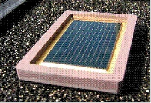
Calibration: A combination of partial on-board calibration with a sun diffuser and vicarious calibration with ground targets guarantees a high quality radiometric performance. State-of-the-art lossy compression based on wavelet transform is applied to reduce the data volume. The compression ratio is fine tuned for each spectral band to ensure that there is no significant impact on image quality.
The observation data are digitised on 12 bit. A shutter mechanism is implemented to prevent the instrument from direct viewing of the sun in orbit and from contamination during launch. The average observation time per orbit is 16.3 minutes, while the peak value is 31 minutes (duty cycle of about 16-31%).
Imager type | Pushbroom instrument |
Spectral range (total of 13 bands) | 0.4-2.4 µm (VNIR + SWIR) |
Spectral dispersion technique | Dichroic for VNIR and SWIR split |
Mirror dimensions of telescope | M1 = 440 mm x 190 mm |
SSD (Spatial Sampling Distance) | 10 m: (VNIR) B2, B3, B4, B8 (4 bands) |
Swath width | 290 km, FOV= 20.6º |
Detector technologies | Monolithic Si (VNIR); hybrid HgCdTe CMOS (SWIR) |
Detector cooling | Cooling of SWIR detector to < 210 K |
Data quantization | 12 bit |
Instrument mass, power | ~290 kg, < 266 W |
Data rate | 450 Mbit/s after compression |
Table 4: MSI instrument parameters
Spectral bands: MSI features 13 spectral bands spanning from the VNIR (Visible and Near Infrared) to the SWIR (Short-Wave Infrared), featuring 4 spectral bands at 10 m, 6 bands at 20 m and 3 bands at 60 m spatial sampling distance (SSD).
VNIR (Visible and Near Infrared) | SWIR (Short-Wave Infrared) |
Monolithic CMOS (Complementary Metal–Oxide–Semiconductor) | MCT, CTIA (Capacitive Feedback Transimpedance Amplifier) ROIC |
10 filters | 3 filters |
7.5-15 µm pitch | 15 µm pitch |
31,152-15,576 pixels | 15,576 pixels |
293K | 195±0.2K |
1 TDI (Time Delay Integration) stage for 2 lines | 1 TDI stage for 2 lines, 2 additional lines for pixel deselection |
Table 5: Specification of VNIR and SWIR FPAs 49)
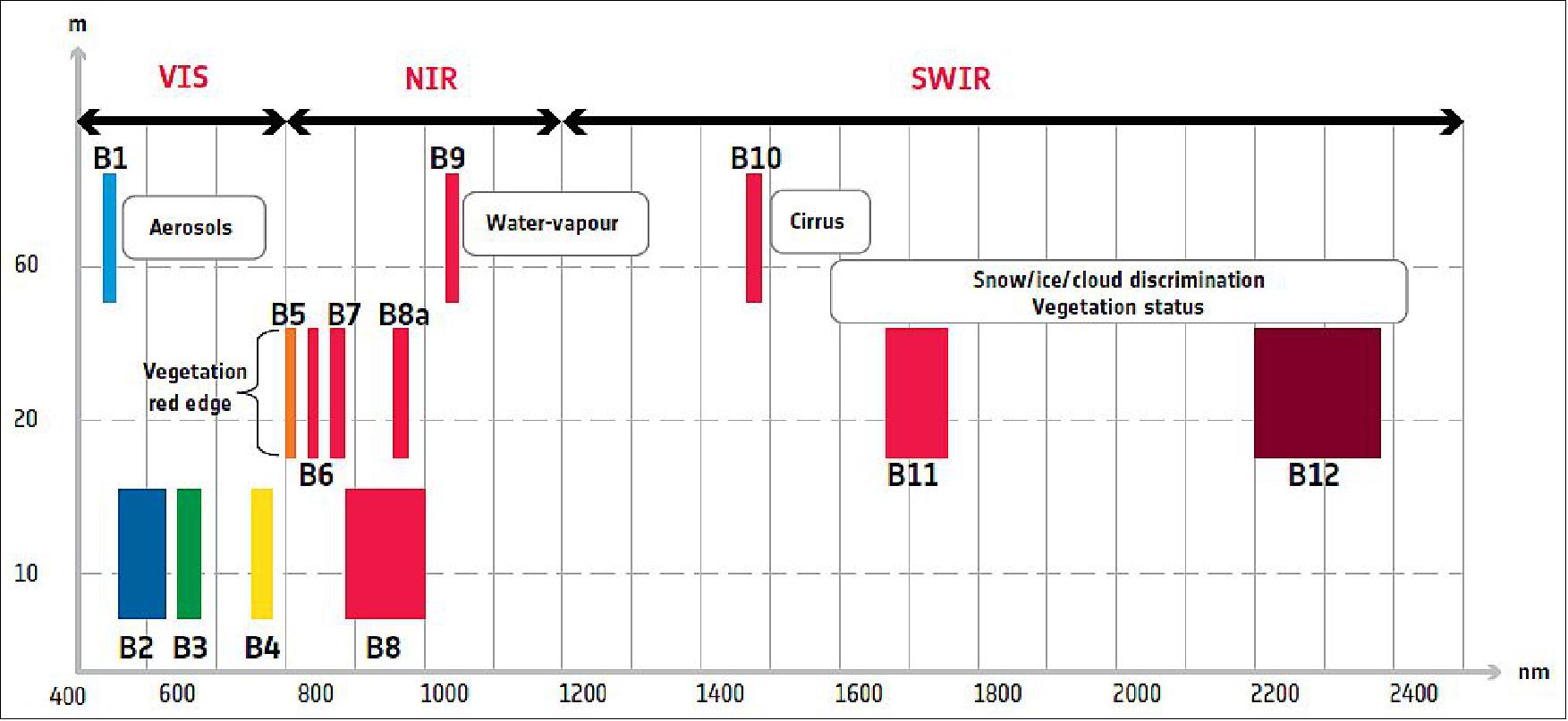
Spectral bands (centre wavelength in nm/SSD in m) | Mission objective | Measurement or calibration |
B1 (443/20/60), B2 (490/65/10) & | Aerosols correction |
|
B8 (842/115/10), B8a (865/20/20), | Water vapour correction | |
B10 (1375/20/60) | Circus detection | |
B2 (490/65/10), B3 (560/35/10), B4 (665/30/10), | Land cover classification, |
|
Table 6: MSI spectral band specification
The filter-based pushbroom MSI instrument features a unique mirror silicon carbide off-axis telescope (TMA) with a 150 mm pupil feeding two focal planes spectrally separated by a dichroic filter. The telescope comprises three aspheric mirrors: M2 mirror is a simple conic surface, whereas the other mirrors need more aspherisation terms. The spectral filtering onto the different VNIR and SWIR spectral bands is ensured by slit filters mounted on top of the detectors. These filters provide the required spectral isolation.
CMOS and hybrid HgCdTe (MCT) detectors are selected to cover the VNIR and SWIR bands. The MSI instrument includes a sun CSM (Calibration and Shutter Mechanism). The 1.4 Tbit image video stream, once acquired and digitised, is compressed inside the instrument.
The instrument carries one external sensor assembly that provides the attitude and pointing reference (star tracker assembly) to ensure a 20 m pointing accuracy on the ground before image correction.
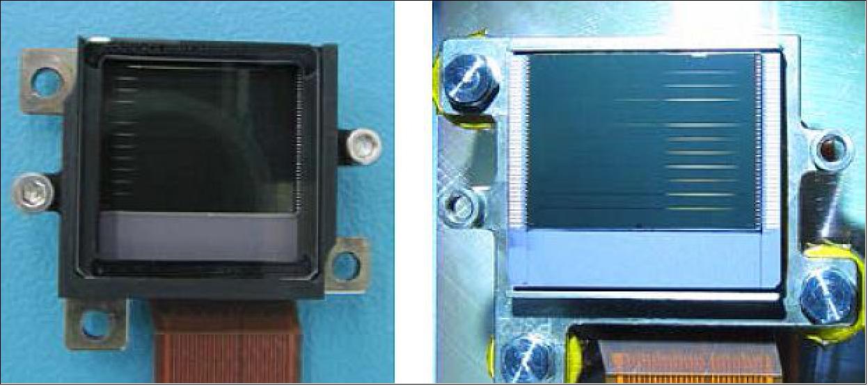
The detectors are built by Airbus Defence and Space-ISAE-e2v: they are made of a CMOS die, using 0.35µm CMOS process, integrated in a ceramic package. The VNIR detector has ten spectral bands, two of them featuring an adjacent physical line allowing TDI operating mode, with digital summation performed at VCU (Video and Compression Unit) level. On-chip analog CDS (Correlated Double Sampling) allows a readout noise of the order of 130 µV rms. For each detector, the ten bands are read through 3 outputs at a sample rate of 4.8MHz. The detector sensitivity has been adjusted for each band through CVF (Charge to Voltage conversion Factor) in view of meeting SNR specifications for a reference flux, while avoiding saturation for maximum flux. A black coating deposition on the non-photosensitive area of the CMOS die is implemented to provide high straylight rejection.
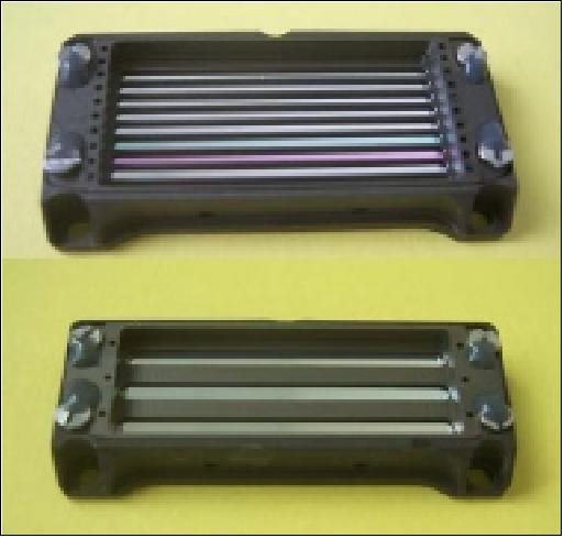
The filter assemblies are procured from Jena Optronik (JOP) in Germany. A filter assembly is made of filter stripes (one for each spectral band) mounted in a Titanium frame. The aims of the filter assembly are: i) to separate the VNIR spectral domain into the ten bands B1 to B9, ii) to prevent stray light effects. This stray light limitation is very efficient since it is made very close to the focal plane. Each filter stripe, corresponding to each spectral band, is aligned and glued in a mechanical mount. A front face frame mechanically clamps the assembly together.
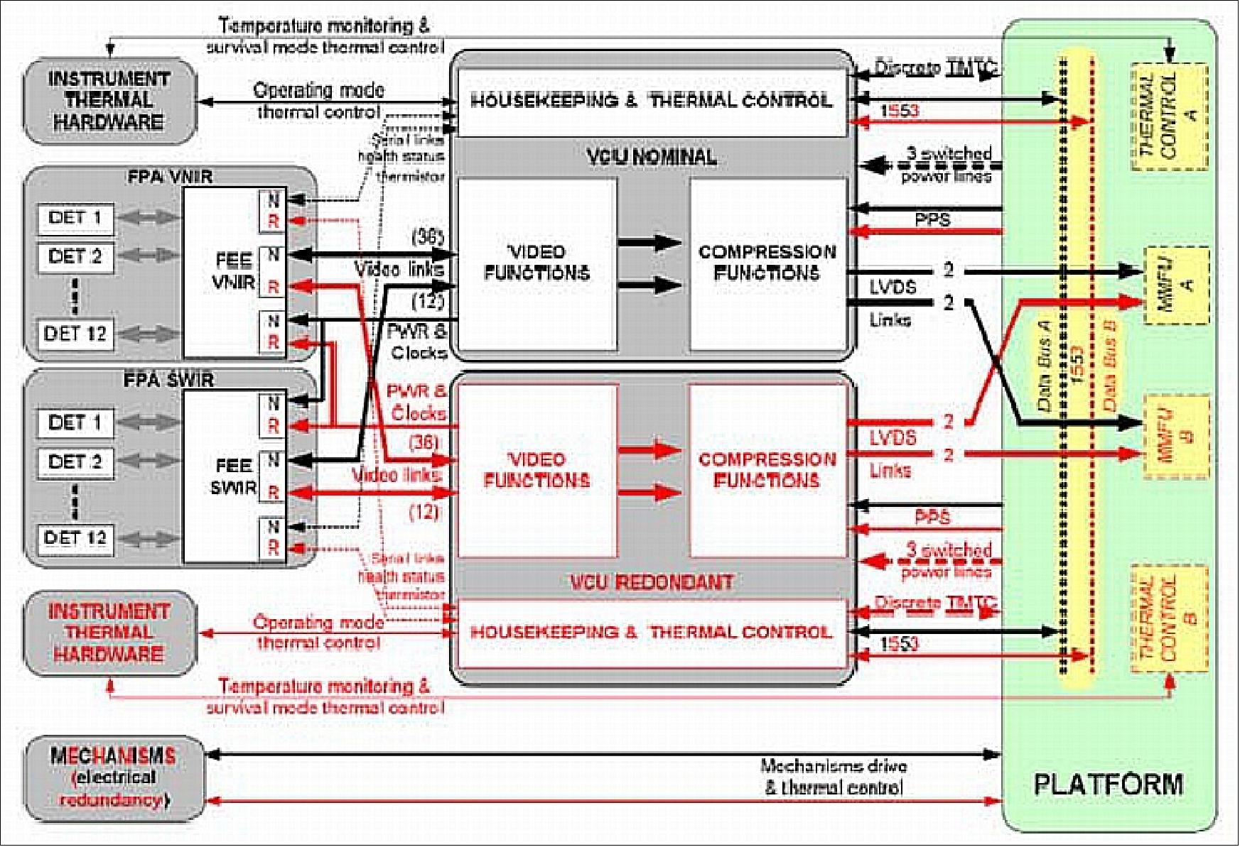
The FEE (Front End Electronics) are procured from CRISA in Spain. Each FEE unit provides electrical interfaces to 3 detectors (power supply, bias voltages, clock and video signals) plus video signal filtering and amplification.
Video and Compression Unit (VCU) is manufactured by JOP and aims i) at processing the video signals delivered by the FEEs : digitization on 12 bits, numerical processing, compression and image CCSDS packet generation, ii) interfacing with the platform (power supply, MIL-BUS, PPS), iii) providing the nominal thermal control of the MSI.
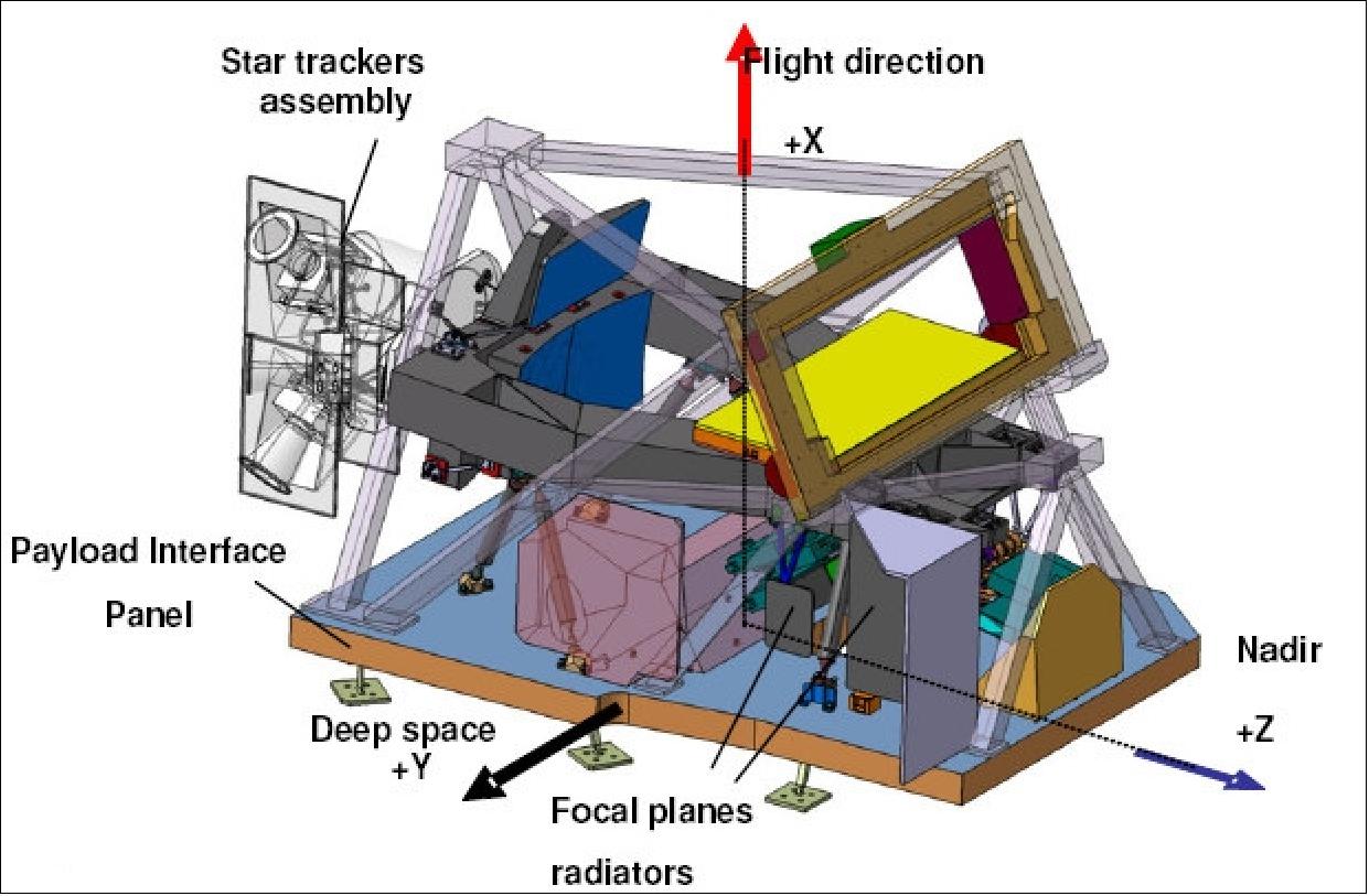
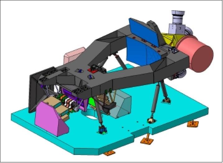
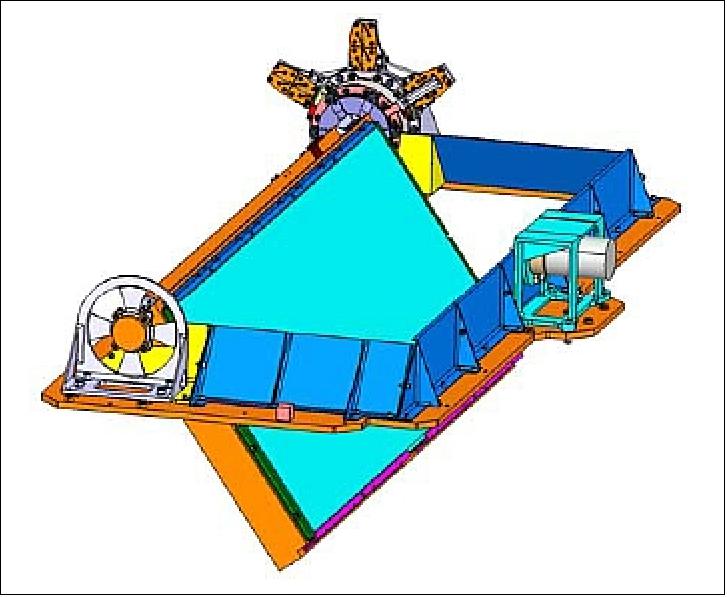
The mechanical structure of MSI instrument holds the 3 mirrors, the beam splitter device, the 2 focal planes and 3 stellar sensors. It is furthermore mounted on the satellite through 3 bolted bipods. This main structure has a size of 1.47 m long x 0.93 m wide x 0.62 m high with a mass of only 44 kg.
The optical face of these mirror blanks have been grounded by Boostec before and after CVD coating (i.e. before polishing), with a shape defect of few tens of a µm. M1 and M2 are designed to be bolted directly on the main SiC structure. M3 is mounted on the same structure through glued bipods. 50)
Mirror | Shape | Mounting | Size (mm) | Mass |
M1 | aspheric of-axis concave | central fixture at back side | 442 x 190 | 2.3 kg |
M2 | aspheric on-axis convex | central fixture at back side | 147 x 118 | 0.3 kg |
M3 | aspheric of-axis concave | glued bipods on outer edges | 556 x 291 | 5.1 kg |
Table 7: MSI mirror characteristics
Mirror manufacturing: The mirror optomechanical design was performed by EADS-Astrium on the basis of the SiC-100 sintered silicon carbide from Boostec who produced the mirror blanks and delivered them to AMOS (Advanced Mechanical and Optical Systems), Liege, Belgium. AMOS is in charge of the deposition of a small layer of CVD-SiC (Chemical Vapour Deposition-Silicon Carbide) on the mirror. The purpose is to generate a non-porous cladding on the mirror surface which allows the polishing process reaching a microroughness state, compatible with the system requirements regarding straylight. 51) 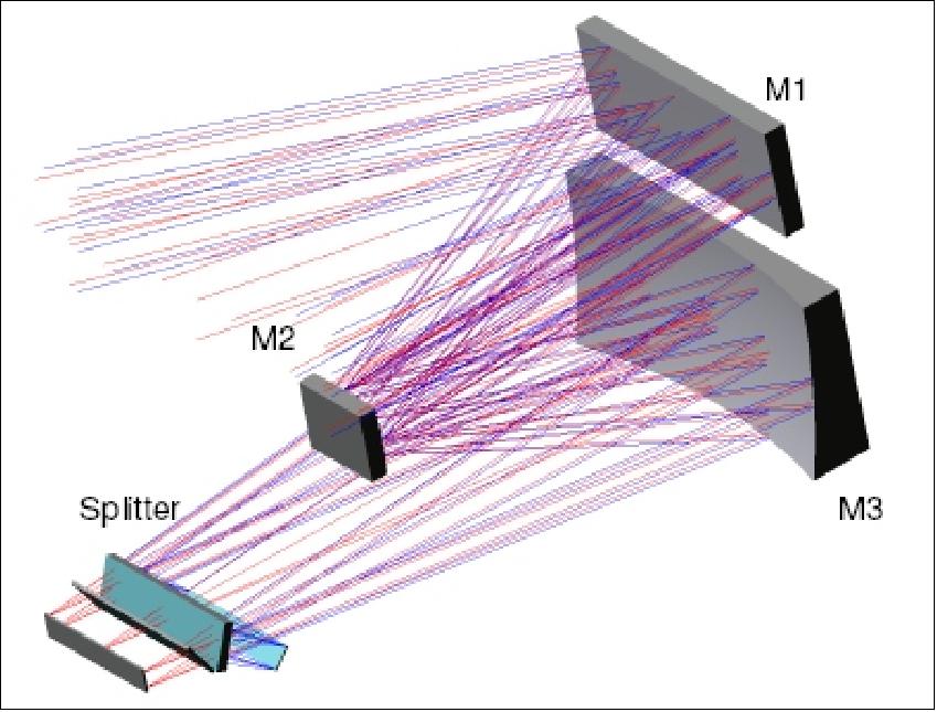
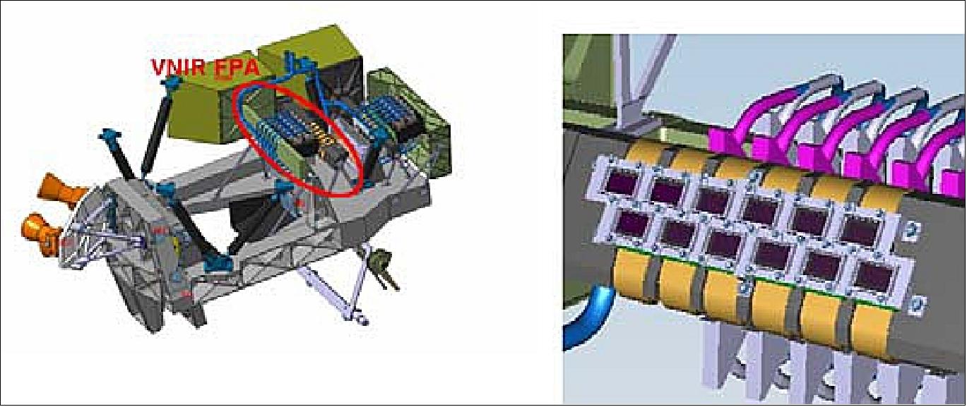
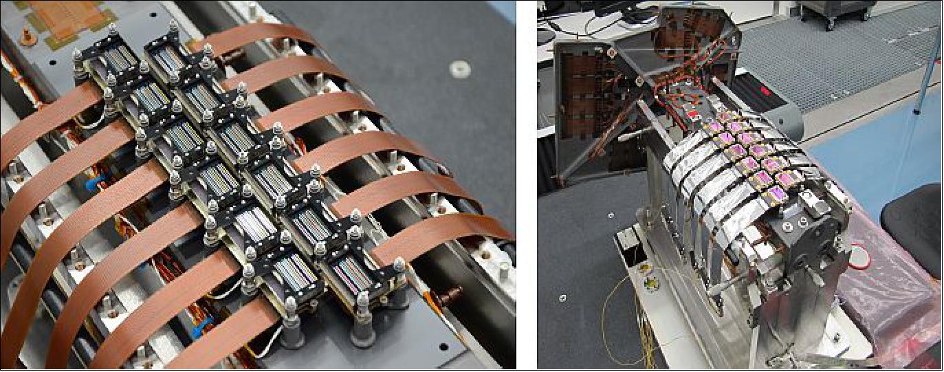
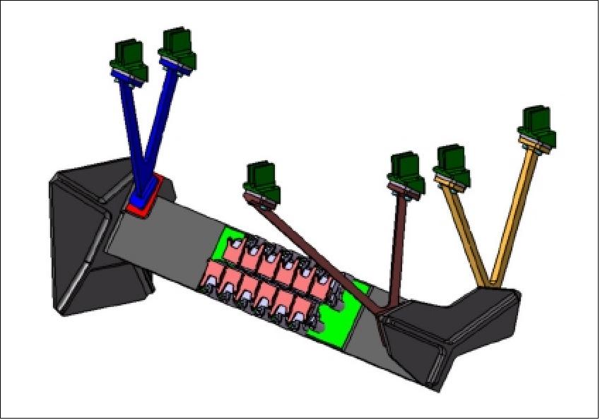
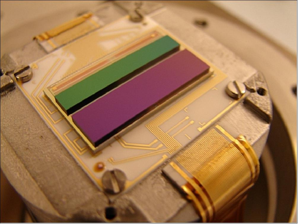
VNIR and SWIR focal plane assemblies: Both focal planes accommodate 12 elementary detectors in two staggered rows to get the required swath. The SWIR focal plane operates at -80ºC whereas the VNIR focal plane operates at 20ºC. Both focal planes are passively cooled. A monolithic SiC structure provides support to the detectors, the filters and their adjustment devices and offers a direct thermal link to the radiator.
Filters and detectors: Dedicated strip filters,mounted on top of each VNIR or SWIR detector, provide the required spectral templates for each spectral band. The VNIR detector is made of a CMOS die, using the 0.35 µm CMOS technology, integrated in a ceramic package. The detector architecture enables “correlated double.”
The so-called VNIR Filter Assembly contains 10 VNIR bands (from 443 nm to 945 nm) and the so-called SWIR Filter Assembly includes 3 SWIR bands (from 1375 nm to 2190 nm). The sophisticated development of the filter assemblies is caused by the specified spectral performance parameters and the high stray light requirements due to the topology of the spectral bands. 52)
Sampling for the 10 VNIR spectral bands along with TDI (Time Delay IntegrationI) mode for the 10 m bands. Black coating on the die eliminates scattering.
The SWIR detector is made of an HgCdTe photosensitive material hybridised to a silicon readout circuit (ROIC) and integrated into a dedicated hermetic package. The SWIR detector has three spectral bands for which the spectral efficiency has been optimised. The B11 and B12 bands are being operated in (TDI) mode.
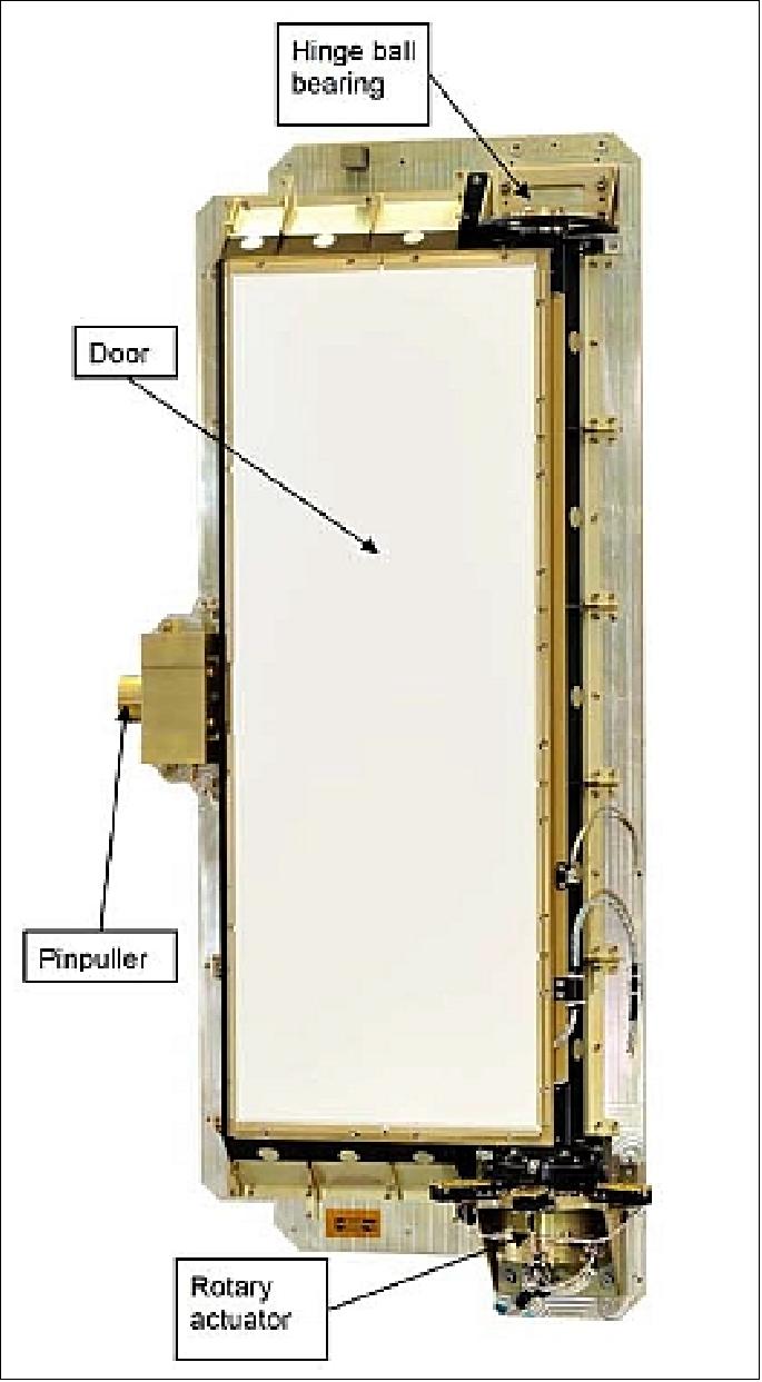
CSM (Calibration and Shutter Mechanism): In MSI, the two functions of calibration and shutter are gathered in one single mechanism to reduce mass, cost and quantity of mechanisms of the instrument, increasing its reliability at the same time. The CSM is located at the entrance of MSI, a rectangular device of ~ 80 cm x 30 cm, mounted on the frame of the secondary structure. The design and development of the CSM is provided by Sener Ingenieria y Sistemas, S.A., Spain. 53)
Requirements and design drivers:
• During launch the CSM has to protect the instrument from sun illumination and contamination by covering the instrument entrance with a rectangular plate (named the door). This is the close position, which has to be maintained under the action of the launch loads.
• Once in orbit, the following functions are required from the CSM:
- To allow Earth observation to the instrument (MSI) the door needs to rotate from the close position 63º inwards the instrument and maintain it stable without power. This is the open position.
- From time to time, in calibration mode of the MSI, the CSM inserts a sun diffuser in front of the primary mirror and the sun diffuser is illuminated by direct solar flux. This mode corresponds to a door position located 55º from the close position outward the instrument. This position must be also stable without any power supply.
- In case of emergency, the CSM has to rotate the door to the close position from any initial position to prevent the sunlight to heat sensible components of the instrument. Similarly to the previous positions, the close position shall be stable without power supply.
A face to face ball bearing as rotation axis hinge in the opposite side of the actuator is used supported by means of an axially flexible support. Apart from that the pinpuller mounted on a flexible support, holds the door during launch by means of a cylindrical contact with respect to the door bushing. This design is the result of the optimization made in order to reach a stiff and robust but light and hyper-statically low constrained mechanism to make it compatible under possible thermal environments.
The pinpuller provides a reliable launch locking device and allows after pin retraction the mechanism to rotate in both senses.
Storage Technology Introduction
MMFU (Mass Memory and Formatting Unit)
The introduction of MMFU by EADS Astrium GmbH and IDA (Institut für Datentechnik und Kommunikationsnetze) at TU Braunschweig represents a new spaceborne storage technology based on SLC (Single Level Cell) NAND-Flash memory devices.
Note: NAND (Not And) is a Boolean logic operation that is true if any single input is false. Two-input NAND gates are often used as the sole logic element on gate array chips, because all Boolean operations can be created from NAND gates.
The NAND storage technology is not only an established technology in commercial applications but represents also a real and effective alternative for mass memory systems in space. The main advantages of the NAND-Flash technology are: a) the non-volatile data storage capability and b) the substantially higher storage density.
In the commercial world the NAND technology has become the preferred solution for storing larger quantities of data on devices such as SSDs (Solid State Drives), USB (Universal Serial Bus) Flash memory sticks, digital cameras, mobile phones and MP3-Players. In the space business, this technology has been used in some experiments only, but not in the frame of large scale mass memory systems. This is now going to be changed. 54) 55) 56)
Astrium and IDA have continuously worked for over seven years on the subject “NAND-Flash Technology for Space”. In the frame of an ESA study dubbed SGDR (Safe Guard Data Recorder) this NAND-Flash technology has been introduced and intensively evaluated.
As a result of this extensive testing, the radiation effects of this technology are well known meanwhile and appropriate error handling mechanisms to cope with the observed effects have been developed. For the S2 (Sentinel-2) mission, a complete qualification program has been performed including radiation tests, assembly qualification, construction analysis, electrical characterization, reliability tests like burn-in, destructive physical analysis, stress and life tests.
All these investments led to the final conclusion that the selected SLC NAND-Flash is an adequate technology for high capacity memory systems for space, even for systems with very high data integrity requirements.
Table 8 lists some main requirements and provides in parallel the related figures of two Astrium MMFU implementations. The first implementation is based on SLC NAND-Flash devices, and the second option uses SDR-SDRAM devices, which was the initially required baseline technology for this mission.
Parameter | Requirement | Astrium MMFU | |
NAND-Flash | SDR-SDRAM | ||
User storage capacity | 2.4 Tbit (EoL) | 6 Tbit (BoL) | 2.8 Tbit (BoL) |
No of memory modules | - | 3 | 11 |
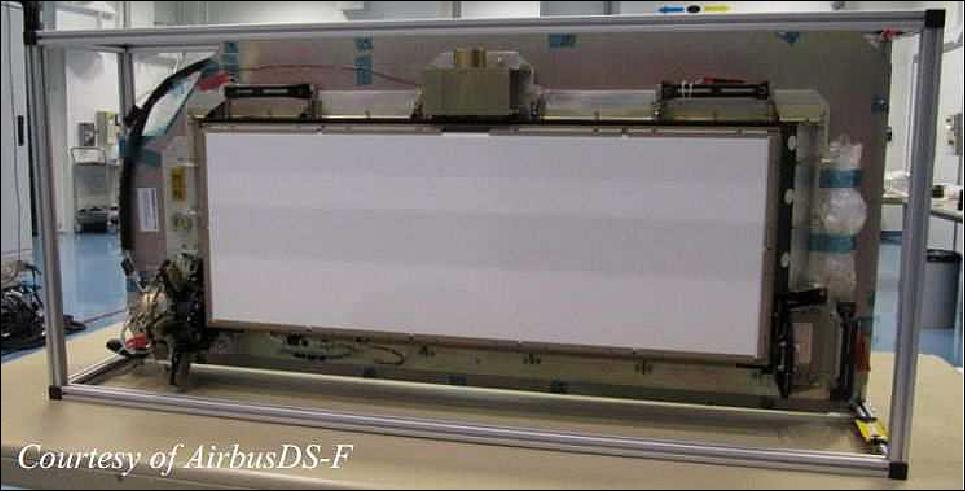
Mass | ≤ 29 kg | < 15 kg | < 27 kg |
Max volume (L x H x W) | 710 mm x 260 mm x 310 mm | 345 mm x 240 mm x 302 mm | 598 mm x 240 mm x 302 mm |
Power (record & replay) | ≤ 130 W | < 54 W | < 126 W |
Power (data retention) | - | < 29 W (0 W) | < 108 W |
Instrument input data rate | 490 Mbit/s + 80 kbit/s (housekeeping) | ||
Output data rate (downlink) | 2 x 280 Mbit/s | ||
Life time in orbit | up to 12.5 years | ||
Reliability | ≥ 0.98 | 0.988 | > 0.98 |
Bit error rate (GCR) per day | ≤ 9 x 10-13 / day | 5.9 x 10⁻¹⁴ / day | < 9 x 10-13 / day |
Table 8: Sentinel-2 MMFU requirements and resulting implementations
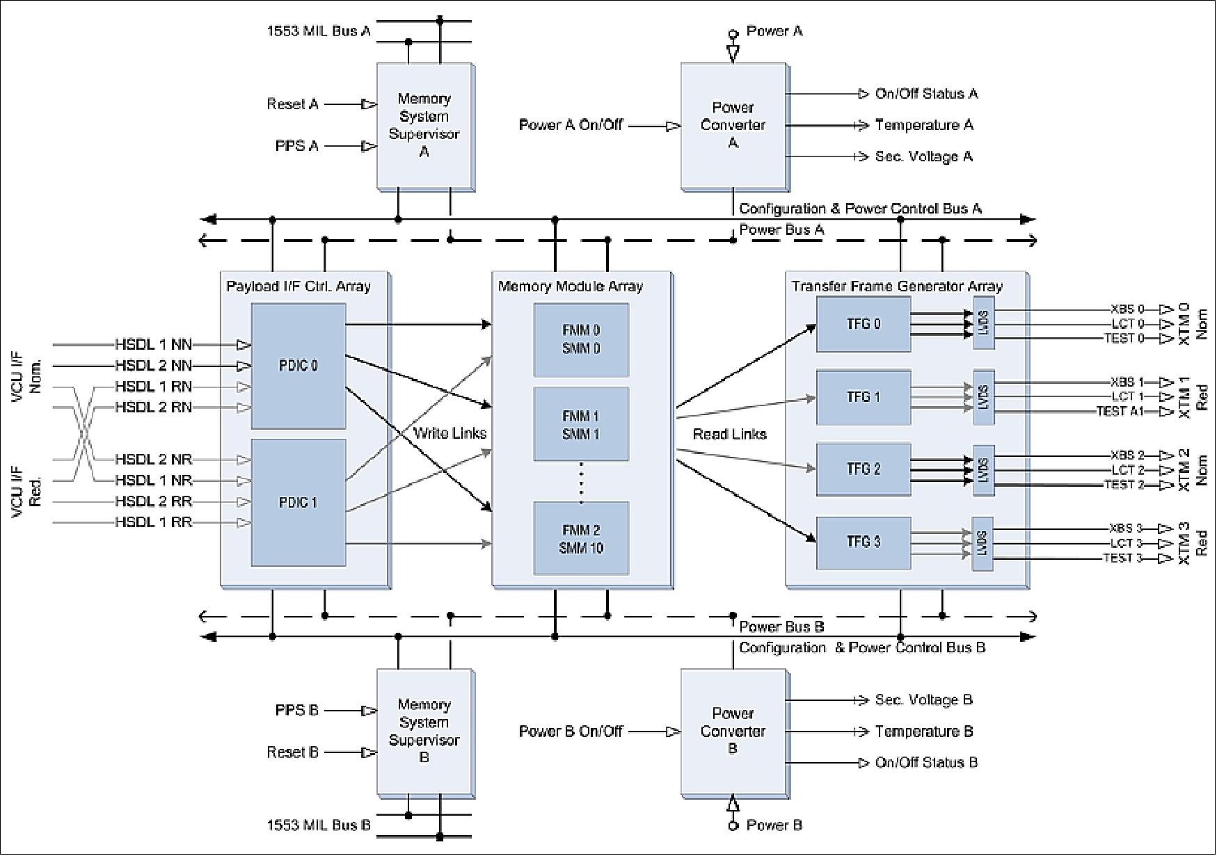
The related simplified architectural block diagram of the Astrium Sentinel-2 MMFU is shown in Figure 34. The MMFU receives two parallel data streams either from the nominal or redundant VCU (Video Compression Unit). The interfaces are cross-strapped with redundant PDICs (Payload Data Interface Controllers). After reception and adaptation to internal data formats of the received source packets, the data is stored in memory modules. FMM (Flash Memory Module) and respectively SMM for the SDR-SDRAM memory module. For replay, the data is read out from two parallel operated memory modules and routed via two active TFGs (Transfer Frame Generators) providing interfaces for downlink and test. The system is controlled by a Memory System Supervisor, which is based on an ERC32 processor. The required supply voltages are provided by a power converter.
Each function is implemented by nominal and redundant hardware components. The functions and boards are summarised in Table 9:
Function | MMFU with NAND-Flash | MMFU with SDR-SDRAM | ||
Modules (Functions) | Boards (Physical Assembly) | Modules (Functions) | Boards (Physical Assembly) | |
Memory System Supervisor | 2 | 2 | 2 | 2 |
Payload Data Interface Controller | 2 | 1 | 2 | 1 |
Memory Modules | 3 | 3 | 11 | 11 |
Transfer Frame Generators | 4 | 2 | 4 | 2 |
Power Converters | 2 | 2 | 2 | 2 |
Total Board Count |
| 10 |
| 18 |
Table 9: Number of functions and boards
Storage capacity: Astrium uses a standard format for all boards. Therefore the maximum number of memory and other devices which can be assembled on one board is limited by this form factor. Both types of memory modules are nearly identical in form, fit and function and because they can be mutually replaced; this represents a good basis for comparison.
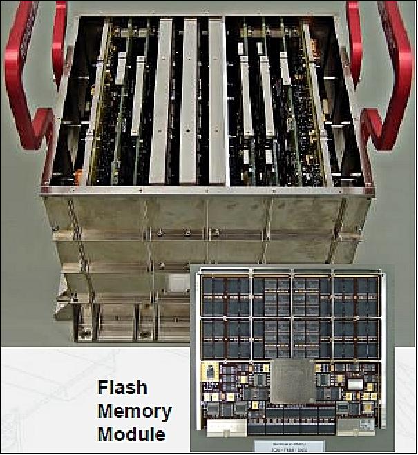
The selected NAND-Flash device provides a capacity of 32 Gbit plus some spare. It is realised by means of four 8 Gbit dies encapsulated in a standard TSOP1 package. In total, the FMM (Flash Memory Module) includes 76 devices. The devices are arranged in four partitions which can be independently powered. A partition represents also the lowest level for reconfiguration. Each partition contains sixteen devices to store user data and three devices that are used to store parity information. This configuration enables single symbol error correction and double symbol error detection.
The SDRAM based memory module has a similar organisation. There are also four partitions and each device for single symbol error correction. A device is represented by a stack which contains eight SDRAM chips with a capacity of 512 Mbit each. From this follows the user storage capacity per memory module and some other parameters as listed in Table 10.
The number of FMM modules is determined by the total data rate and the operational concept, which requires the operation of two independent data streams. Therefore there are two memory modules operated in parallel. The third one is provided for redundancy.
The number of SMM modules is mainly determined by the required capacity. Also here two modules are operated in parallel and one SMM is included for reliability reasons.
Performance data | Unit | SLC NAND-FMM (Flash Memory Module) | SDR-SMM (SDRAM Memory Module) |
Baseline technology |
| NAND-Flash | SDR |
Device package |
| Quad Die Stack TSOP I | Eight Die Stack TSOP II |
Die capacity | Gbit | 8 | 0.5 |
Device capacity | Gbit | 32 | 4 |
Partition organisation | devices | 16+3 | 16+2 |
Data bus width | bit | 128+24 | 128+16 |
Partition net capacity | Gbit | 512 | 64 |
Count of partitions per module |
| 4 | 4 |
Count of devices per module |
| 76 | 72 |
Module net capacity | Gbit | 2048 | 256 |
Accessible unit (read/write) | kbyte | 256 | 0.5 (by design) |
Accessible unit (erase) | MByte | 16 | N/A |
Type of module data interfaces |
| Channel link | Channel link |
Max. Input data rate | Mit/s | 800 | 2400 |
Max. Output data rate | Mbit/s | 800 | 1200 |
Module power (max data rate) | W | 10.5 | 14 |
Module power (data retention) | W | 0 (4) | 8 |
Module size | mm x mm | 200 x 243.5 | 200 x 243.5 |
Module mass | kg | 0.85 | 1.15 |
Table 10: Performance characteristics of Astrium Sentinel 2 MMFU memory modules
The much higher storage density of the NAND-Flash devices (factor of 8) leads to a massive reduction in the number of required memory modules. For a mass memory system this becomes especially evident, if there is a requirement for a large user capacity as in case of the Sentinel-2 MMFU. Further positive aspects evolve with reduction of the number of modules. The complete system design from electrical and mechanical point of view is greatly relaxed.
Mass and volume: With reduction of the number of memory modules, it is obvious that directly related physical budgets like mass and volume, decline accordingly. Mass is always a critical issue for space missions which can be reduced by using NAND-Flash technology; but also the complete system design of a satellite, in terms of mass, power, thermal and other aspects, can be positively influenced by applying NAND-Flash based memory systems. In case of the Sentinel-2 MMFU, indeed 14 Kg (about 50%) can be saved.
Power: The power consumption is also reduced by more than 50%, which mainly due by the number of memory modules operated in parallel. In the case of Flash, there are only two active memory modules. In the case of the SDRAM technology, 10 memory modules are operated in parallel: up to four modules for data access, two modules for read, two modules for write, and all other modules in data retention mode. Data retention means that the modules store user data and the SDRAM chips have to be refreshed and scrubbed for error detection and correction.
In contrast, a Flash-based memory module can be completely switched off without loss of data in the data retention mode. For a minimum, the partitions can be switched off and the power consumption of the controller part of the module is reduced due to low activity.
It is not obvious that, in all cases, NAND-Flash consumes less power than SDR-SDRAM based systems. The power consumption depends on several factors like required storage capacity, data rates and operations. Generally it can be said that as long as the required storage capacity determines the number of memory devices, Flash might be the better choice. If the number of memory devices is determined by the required data rate, SDRAM based systems may have better performance from a power consumption point of view.
Data rates: Table 11 shows that SDR-SDRAM devices provide a much better performance from data rate point of view. The overall performance of a memory module depends on further characteristics like type of interfaces, memory controller performance, and maximum power consumption and others. Generally an SDRAM based memory module has advantages in terms of access speed.
Performance parameter | SLC NAND-Flash | SDR-SDRAM |
Die capacity (not stacked) | 8 Gbit | 512 Mbit |
Operating voltage | 2.7 V – 3.6 V | 3.0 V – 3.6 V |
Data bus width | 8 bit | 8 bit |
Temperature range (std. available) | - 40ºC to + 85ºC | 0ºC to +70ºC |
Maximum read performance @ IO clock | < 250 Mbit/s @ 40 MHz on page level (4 k x 8) | < 800 Mbit/s @ 100 MHz burst operation |
Erase time | 2 ms on block level (256 k x 8) | N/A |
Endurance | > 105 | ∞ |
Data retention | 10 years | N/A |
Table 11: Performance characteristics of the memory devices
The lower performance of NAND-Flash is determined by three characteristics. During writing the NAND-Flash devices need to be programmed and this takes a time of about 700 µs per 4 kbyte data (one device page). Additionally the so-called blocks of a NAND-Flash device have to be erased before programming. This consumes another 2 ms per block (64 pages). Last but not least, the selected NAND-Flash devices use an eight bit interface for serial commanding, addressing and data transfer with a maximum operating frequency of 40 MHz.
This lack in performance can be mitigated by mainly two measures. The first straight forward measure is parallel operation of NAND-Flash devices. The second measure is interleaved access to several NAND-Flash devices. Interleaving uses the programming time of a NAND-Flash device to write in parallel the next device. These methods allow increasing the write access performance.
Lifetime and reliability: NAND-Flash devices provide a limited endurance. This is caused by an inherent wear out mechanism of the Flash memory cells which limits the number of erase and write cycles to about 105 cycles. To mitigate the endurance limitation, most Flash memory systems are equipped with an address management system, which distributes the write accesses rather uniformly over the address space. This technique is called wear leveling.
Furthermore the very high device capacity of NAND-Flash devices offers the opportunity to implement a physical address space, which exceeds the required logical user address space by a factor of n. This enhances the wear out limit of the logical addresses by the factor of n too. Hence there are two methods to keep the total count of write accesses to the same physical address below the wear out limit.
Radiation and error rates: In general, sensitivity of electronic devices to space radiation is a major topic and is also shortly discussed here through a comparison of NAND-Flash and SDR-SDRAM devices.
The mass memory system based on NAND-Flash shows clear advantages and fits well to the high storage capacity and moderate data rates of the Sentinel-2 application. The very high storage density of the NAND-Flash devices leads to a reduced number of memory modules with advantages in terms of power consumption, mass and volume. Furthermore this feature improves the reliability and eases the system design from mechanical and electrical points of view.
Storage capacity | 2400 Gbit (EOL) with Flash technology |
Input data rate | 2 x 540 Mbit/s |
Instrument mass, size | 14 kg, L: 302 x W: 345 x H: 240 mm |
Power consumption | < 35 W |
Simultaneous record and replay | |
Flexible real-time SW based embedded File Management System with PUS (Packet Utilisation Standard) services | |
CCSDS conform output Data Formatting at a data rate of 2 x 280 Mbit/s | |
7.5 years lifetime in-orbit | |
Table 12: Parameters of the Sentinel-2 MMFU 57)
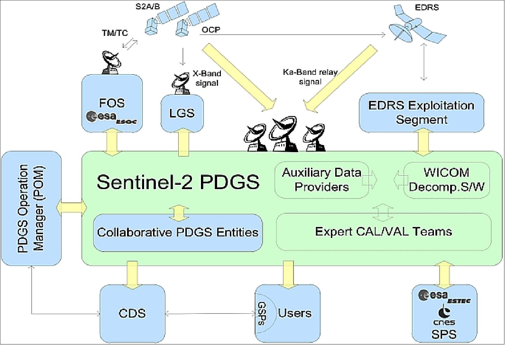
Ground Segment
For Copernicus operations, ESA has defined the concept and architecture for the Copernicus Core ground segment, consisting of a Flight Operations Segment (FOS) and a Payload Data Ground Segment (PDGS). Whereas the flight operations and the mission control of Sentinel-1 and -2 is performed by ESOC (ESAs European Space Operations Center in Darmstadt, Germany), the operations of Sentinel-3 and the Sentinel-4/-5 attached payloads to meteorological satellites is performed by EUMETSAT.
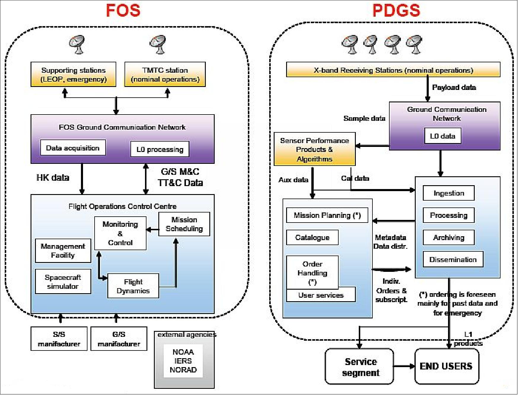
The ground segment includes the following elements:
• Flight Operations Segment (FOS): The FOS is responsible for all flight operations of the Sentinel-2 spacecraft including monitoring and control, execution of all platform activities, and commanding of the payload schedules. It is based at ESOC, Darmstadt in Germany and comprises the Ground Station and Communications Network, the Flight Operations Control Centre and the General Purpose Communication Network.
• Payload Data Ground Segment (PDGS): The PDGS is responsible for payload and downlink planning, data acquisition, processing, archiving and downstream distribution of the Sentinel-2 satellite data, while contributing to the overall monitoring of the payload and platform in coordination with the FOS.
The Service Segment, geographically decentralised, utilises the satellite data in combination with other data to deliver customised information services to the final users.
The baseline ground station network includes four core X-band ground stations for payload observation data downlink and one S-band station for Telemetry, Tracking and Control (TT&C). To a limited extent, the system can also accommodate some direct receiving local user ground stations for Near-Real Time applications.
The systematic activities of the PDGS include the coordinated planning of the mission subsystems and all processes cascading from the data acquired from the Sentinel-2 constellation, mainly:
1) The automated and recurrent planning of the satellite observations and transmission to a network of distributed X-band ground stations
2) The systematic acquisition and safeguarding of all spacecraft acquired data, and its processing into higher level products ensuring quality and timeliness targets
3) The recurrent calibration of the instrument as triggered by the quality control processes
4) The automated product circulation across PDGS distributed archives to ensure the required availability and reliability of the data towards users
5) The long-term archiving of all mission data with embedded redundancy over the mission lifetime and beyond.
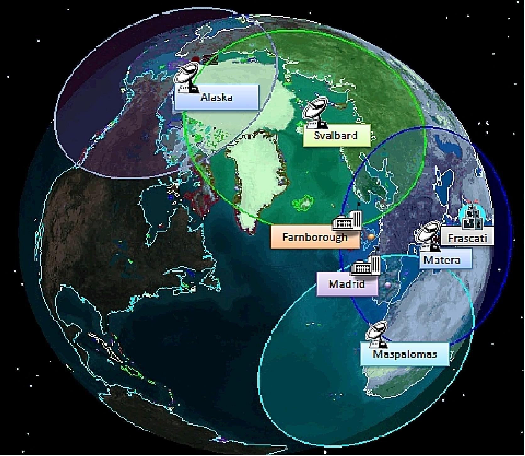
• CGS (Core Ground Stations: Matera (Italy), Maspalomas (Spain), Svalbard (Norway), Alaska (USA).
• PAC (Processing/Archiving Center): Farnborough (UK), Madrid (Spain)
• MPC (Mission Performance Cluster): TBD
• PDMC (Payload Data Management Centre): ESA/ESRIN, Frascati, Italy.
Mission Performance Cluster
The Mission Performance Cluster (MPC) is responsible for ensuring that Copernicus User Level Data meets calibration and validation standards. It monitors instrument performance, assesses data quality, and ensures the data meets product specifications. The MPC also handles the development and maintenance of calibration and validation information, including scientific algorithms and Level-2 data processors, to maintain high data quality throughout the mission.
| Level-1 image processing includes: | - a) Radiometric corrections: straylight/crosstalk correction and defective pixels exclusion, de-noising, de-convolution, relative and absolute calibration - b) Geometric corrections: co-registration inter-bands and inter-detectors, ortho-rectification. |
| Level 2 image processing includes: | - a) Cloud screening - b) Atmospheric corrections: including thin cirrus, slope and adjacency effects correction - c) Geophysical variables retrieval algorithms: e.g. fAPAR, leaf chlorophyll content, leaf area index, land cover classification. |
| Level 3 provides spatio-temporal synthesis | Simulation of cloud corrections within a Level 2 image |
Data Preservation and Long Term Archiving
The Data Preservation and Long-Term Archiving (LTA) function ensures secure, long-term storage of mission-critical Copernicus data. It manages data ingestion, safe storage, querying, retrieval, and archive integrity, providing consistent access through an Archive Interface Point (AIP). The LTA service includes geographically redundant instances for resilience and autonomous operation, ensuring data availability even if one instance fails. 80)The Precise Orbit Determination (POD)
The Precise Orbit Determination (POD) function provides highly accurate orbital and auxiliary data for Copernicus Sentinel satellites and ensures precise satellite positioning for accurate data geolocation, assessing GPS sensor performance onboard and validating data quality. It coordinates with GPS data providers, ILRS, and agencies like CNES and EUMETSAT. Using GNSS data from the satellites, POD generates essential files for systematic data production and geolocation accuracy across Copernicus missions.
Copernicus / Sentinel Data Policy
The principles of the Sentinel data policy, jointly established by EC and ESA, are based on a full and open access to the data:
• anybody can access acquired Sentinel data; in particular, no difference is made between public, commercial and scientific use and in between European or non-European users (on a best effort basis, taking into consideration technical and financial constraints);
• the licences for the Sentinel data itself are free of charge;
• the Sentinel data will be made available to the users via a "generic" online access mode, free of charge. "Generic" online access is subject to a user registration process and to the acceptation of generic terms and conditions;
• additional access modes and the delivery of additional products will be tailored to specific user needs, and therefore subject to tailored conditions;
• In the event security restrictions apply to specific Sentinel data affecting data availability or timeliness, specific operational procedures will be activated.
ESA Member States approved these principles in September 2009. 60) 61) 62) 63) 64)
Cloud-based Infrastructure Architecture
The Copernicus Space Component (CSC) moved all the Ground Segment service-oriented operations to a cloud-based infrastructure since 2019 due to the high demand of data required, providing scalability, flexibility, and resilience, supporting current and future data needs.
Interconnected services (e.g., data acquisition, processing) ensure robust operations, even during disruptions. New missions will easily integrate into this scalable, adaptive framework and improved satellite observation planning, data quality control, and archiving, with open access provided through the Copernicus Data Space Ecosystem.

A key element of the Copernicus Ground Segment architecture is the reference system, which is a cloud-based, open-source framework designed to ensure flexibility and avoid dependency on specific vendors for data production and download.
Data Acquisition
The data acquisition function for Copernicus missions is managed through dedicated Acquisition Services tailored to each satellite’s requirements. It involves multiple Ground Stations operating autonomously to capture and transmit data based on mission-specific downlink schedules, overseen by a central Mission Planning system and the Sentinels Resource Allocation (SRA) system. 80)
Each acquisition service, X-Band, EDRS (European Data Relay Satellite), and Ka-Band, provides tailored support to meet the unique data downlink requirements of Copernicus missions.
The X-Band Acquisition primarily serves routine Copernicus mission needs, supporting data downlink and delivery through autonomous ground stations for data demodulation and stream generation. The EDRS Acquisition, (for Sentinel-1 and Sentinel-2), uses optical and Ka-Band links to enhance data relay and downlink operations, with designated scheduling and maintenance of data interfaces. The Ka-Band Acquisition is essential for higher-data-volume missions within the Copernicus Expansion (COP EX) program, fulfilling increased downlink demands with support for the CFDP protocol, ensuring efficient data transfer to ground stations.
The EDRS GEO satellite relays the data to the ground via a Ka-band link. Optionally, the Ka-band downlink is planned to be encrypted, e.g. in support to security relevant applications. Two EDRS geo-stationary satellites are currently planned, providing in-orbit redundancy to the Sentinels. 59)
EDRS provides the same data at the ground station interface as is available at the input to the OCP (Optical Communications Payload) on-board the satellites, using the same interface as the X-band downlink. The EDRS transparently adapts the Sentinels data rate and format to the internal EDRS rate and formats, e.g. EDRS operates at bit rates of 600 Mbit/s and higher.
With EDRS, instrument data is directly down-linked via data relay to processing and archiving centres, while other data continues to be received at X-band ground stations. The allocation of the data to downlink via X-band or EDRS is handled as part of the Sentinel mission planning system and takes into account the visibility zones of the X-band station network and requirements such as timeliness of data.
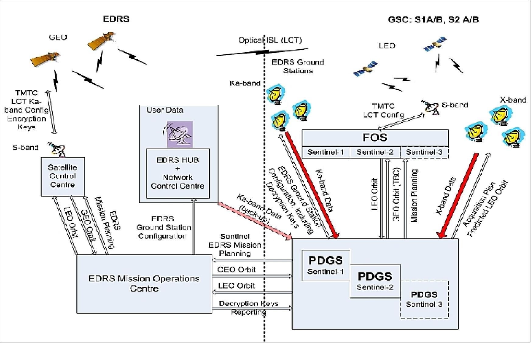
Figure 39: Sentinel missions - EDRS interfaces (image credit: ESA)
Data Access
The Data Access component in the Copernicus Data Space Ecosystem provides users with cloud-based access to Copernicus mission data, including tools for data processing and analysis (IaaS, PaaS, etc.). This service is critical for supporting data needs across all Copernicus missions and is designed to ensure continuous availability, hosted on two independent cloud infrastructures for disaster resilience.
The service enables users to download recent and historical mission data on-demand. Configurable for immediate or archived data access, ensuring flexible retrieval options. Streamlined access provides interactive processing environments, such as Notebooks, for analyzing data directly on the platform, making it easier to handle data without downloading, and on-demand production allows users to generate higher-level data (e.g., Level-1/2) from stored raw data (Level-0) when needed, based on requests.
The core services covered by the data access component include unified identity management system, which allows easy access across all Copernicus Data Space services, data registration, retrieval, metadata management, and visualization, alongside cache storage for efficient data access. Access levels can be configured based on user type (e.g., Open Access, Collaborative, International partners) with specific download quotas and registration protocols.
The platform offers open, free data access and, through this ecosystem, users can perform immediate analyses, develop downstream services, and contribute to Copernicus’s expanding data offerings.
Sen2Coral (SEOM S24Sci Land and Water: Coral Reefs)
The objective of ESA’s SEOM (Scientific Exploration of Operational Missions) Program Sen2Coral is the preparation of the exploitation of the Sentinel-2 mission for coral reefs by developing and validating appropriate, open source algorithm available for the community. The project objectives are the scientific exploitation and validation of the Sentinel-2 MSI (Multispectral Instrument) for mapping (habitat, bathymetry, and water quality) and detection change for coral reef health assessment and monitoring, and algorithm development dedicated to Sentinel-2 capabilities to satisfying these objectives. 74)
To address the extremely interesting and challenging questions posed by this project a consortium of contractors with appropriate background knowledge and skills has been assembled. The consortium comprises:
• ARGANS Limited, UK
• CNR-IREA, Italy
• CS-SI, France
The consortium is complemented by a science team of consultants and partners who are recognised international scientists in the field.
Research Program
• A critical analysis of feedback from scientists and institutions collected through consultations in ESA and Third Party workshops, symposia and conferences.
• Proposal of potential observation scenarios for Sentinel-2 in terms of required spatial coverage and repeat cycle considering user requirements, existing observation initiatives and synergy with other sensors (Landsat, SPOT sensor families).
• Identifying scientific priority areas and providing guidance for future scientific data exploitation projects. 75)
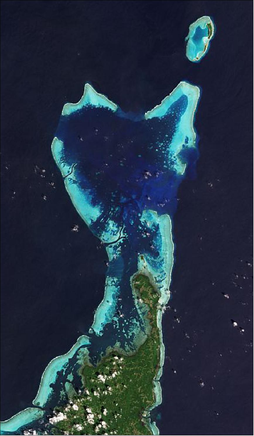
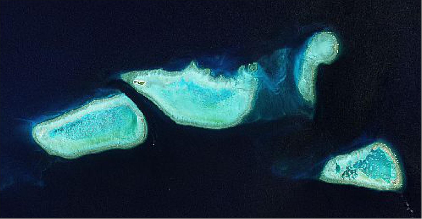
Tropical coral reefs are globally important environments both in terms of preservation of biodiversity and for the substantial economic value their ecosystem services provide to human communities. Managing and monitoring reefs under current environmental threats requires information on their composition and condition, i.e. the spatial and temporal distribution of benthos and substrates within the reef area. Determining the relative abundance of biotic types such as coral and macroalgae is the key for detecting and monitoring important biotic changes such as phase or regime shifts due to changes in environmental conditions. Coral bleaching events, where stressed corals expel their symbiotic algae and turn white in colour, can provide indications of anthropogenic stressors and climate change impacts, while subsequent coral mortality may be a key determinant of future reef state. In addition to monitoring of current status, maps of benthos have the potential to inform management decisions such as the placement of marine protected areas and could in the future be used to seed models to predict ecosystem dynamics.
Project Activities
Background: The degradation of coral reefs is a fact, with 55% of reefs being affected by overfishing and destructive fishing methods, which as the most pervasive threats, whereas 25% of reefs are affected by coastal development and pollution from land, including nutrients from farming and sewage, while one tenth suffer from marine-based pollution (local pressures are most severe in South-East Asia, where nearly 95 per cent of coral reefs are threatened).
In addition the coral reefs’ ecosystems appear to be the first to respond to global climate changes, such as increased sea surface temperature (SST), ultraviolet radiation (UV) and acidification of seawater that results from higher levels of atmospheric CO2 concentration.
Sentinel-2 MSI Data Acquisition
The MSI (Multispectral Instrument) of the Sentinel-2A mission offers several potential technical advantages in the remote sensing of coral reefs due to:
• 10 metre spatial resolution allowing improvement in visual interpretation of reef features, classification accuracy and bathymetry.
• Additional water penetrating optical band improving consistency under varying water conditions, reducing uncertainty in bottom type and bathymetric mapping, deeper bathymetric accuracy and ability to determine water optical properties.
• Additional NIR/SWIR bands enabling more consistent and accurate determination of atmospheric and surface glint correction.
• Short revisit time enabling the use of image series to determine fundamental uncertainties for change detection.
• Addresses the current limited remote sensing acquisition plan covering the coast areas.
Algorithm Development & Data Processing
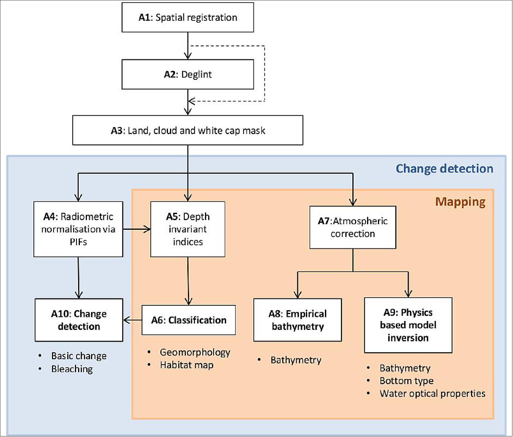
The objective “to develop and validate new algorithms relevant for coral reef monitoring based on Sentinel-2 observations” is addressed by parameterizing existing models for processing hyper-spectral & multi-spectral data and developing pre-processors for these models to build Sentinel-2 data processing algorithms for the retrieval of coral reefs’ static and dynamic characteristics. The code developed is available open source.
Validation and uncertainty analysis involves both comparing Sentinel MSI performance versus Landsat-8 on coral reef mapping objectives and comparing coral reef monitoring products against in situ data from reef sites representative of different composition and structure.
Product Development
To design, verify and validate three coral reef monitoring products making the best use of Sentinel-2 MSI mission characteristics:
• Habitat mapping of coral reefs
• Coral reef change detection
• Bathymetry over coral reefs.
Field Campaign
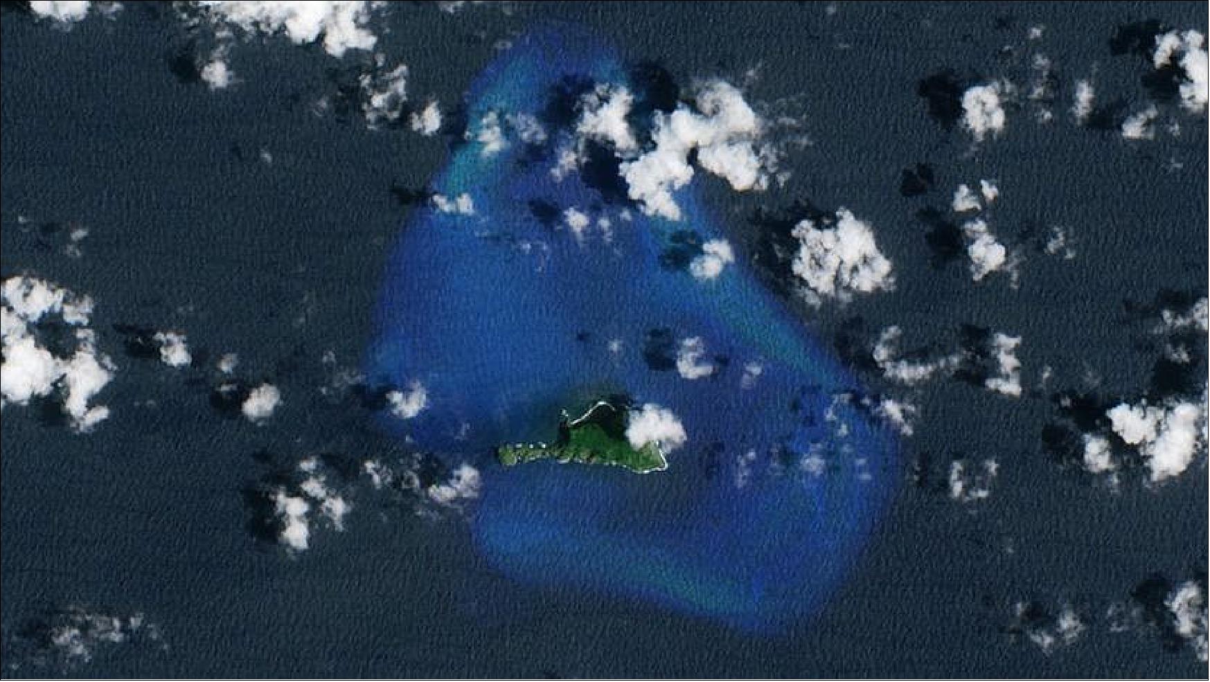
A 6 day field campaign around the South Pacific island of Fatu Huku was undertaken by French scientist Antoine Collin to collect in-situ data to test and validate the capabilities of the Sentinel-2 satellite to monitor coral reef bleaching.
Fatu Huku Island in French Polynesia was chosen as the survey site because of the presence of developed coral reefs and it is an area where water temperatures are high as a result of the current El Niño event. During the survey, water temperatures exceeding 30°C were recorded and coral bleaching, the expulsion of the symbiotic algae that provide energy from sunlight to the coral, was observed to be taking place.
Data collected from this field campaign complements archives of in-situ data collected over previous years from coral reef sites across the globe such as at Heron Island and Lizard Island, in Australia, and reefs around Palau, in the western Pacific Ocean.
References
1) P. Martimort, O. Arino, M. Berger, R. Biasutti, B. Carnicero, U. Del Bello, V. Fernandez, F. Gascon, B. Greco, P. Silvestrin, F. Spoto, O. Sy, “Sentinel-2 Optical High Resolution Mission for GMES Operational Services,” Proceedings of IGARSS 2007 (International Geoscience and Remote Sensing Symposium), Barcelona, Spain, July 23-27, 2007
2) P. Martimort, F. Spoto, B. Koetz, O. Arino, M. Rast, “GMES Sentinel-2, The Optical High Resolution Mission for GMES Operational Services,” July 16, 2007, URL: http://www.earthobservations.org/documents/cop/ag_gams/200707_01/gmes_sentinel2.pdf
3) ESA Sentinel-2 Team, “GMES Sentinel-2 Mission Requirements Document,” Issue 2, Revision 1, 08.03.2010, URL: http://esamultimedia.esa.int/docs/GMES/Sentinel-2_MRD.pdf
4) F. Spoto, M. Berger, “Sentinel-2 Presentation,” March 7-8, 2007, ESA/ESRIN, URL: http://esamultimedia.esa.int/docs/GMES/ESA/4_coloc_GMES_S2_GSC_day_7_8_March_2007.pdf
5) P. Martimort, M. Berger, B. Carnicero, U. Del Bello, V. Fernandez, F. Gascon, P. Silvestrin, F. Spoto, Omar Sy, O. Arino, R. Biasutti, B. Greco, “Sentinel-2 : The Optical High Resolution Mission for GMES Operational Services,” ESA Bulletin, No 131, Aug. 2007, pp. 19-23, URL: http://www.esa.int/esapub/bulletin/bulletin131/bul131b_martimort.pdf
6) Philippe Martimort, “The Optical High Resolution Mission The for GMES Operational Services for Services,” GMES Sentinel-2, AGRISAR Workshop, Noordwijk, The Netherlands, Oct. 15-16, 2007, URL: http://www.dlr.de/hr/Portaldata/32/Resources/dokumente/agrisar/(03)_GMES_S2_Presentation_AGRISAR.pdf
7) F. Spoto, P. Martimort, O. Sy, P. Bargellini, B. Greco, “Sentinel-2: the European operational fast revisit high resolution land observing mission,” Sentinel-2: the European operational fast revisit high resolution land observing mission
8) François Spoto, Philippe Martimort, Omar Sy, Paolo Laberinti, Stefane Carlier, Umberto Del Bello, Valérie Fernandez, Volker Kirschner, Claudia Isola, Matthias Drusch, Pier Bargellini, Franco Marchese, Olivier Colin, Ferran Gascon, Bianca Hoersch, Aimé Meygret, “The GMES Sentinel-2 Operational Mission,” Proceedings of the ESA Living Planet Symposium, SP-686, Bergen Norway, June 28-July 2, 2010
9) “Copernicus: new name for European Earth Observation Programme,” European Commission Press Release, Dec. 12, 2012, URL: http://europa.eu/rapid/press-release_IP-12-1345_en.htm
10) ESA’s Sentinel-2 team, “Color Vision for Copernicus, The story of Sentinel-2,” ESA Bulletin No 161, May 11, 2015, pp. 2-9, URL: http://esamultimedia.esa.int/multimedia/publications/ESA-Bulletin-161/offline/download.pdf
11) “GMES Sentinel-2 satellite contract signed,” April 17, 2008, URL: http://www.esa.int/esaEO/SEMH574XQEF_index_0.html
12) GMES Sentinel-2 Industry Day, Nov. 26, 2007, URL: http://esamultimedia.esa.int/docs/industry/Sentinel/Nov07/Sentinel-2-Industry-Day-Nov-07-Astrium-VGs.pdf
13) https://web.archive.org/web/20130402225802/http://www.astrium.eads.net/media/document/sentinel_2_data_sheet.pdf
14) Francois Spoto, Omar Sy, Paolo Laberinti, Philippe Martimort, Valerie Fernandez, Olivier Colin, Bianca Hoersch, Aime Meygret, “Overview of Sentinel-2,” Proceedings of IGARSS (International Geoscience and Remote Sensing Symposium), Munich, Germany, July 22-27, 2012
15) “Astrium to build ESA's second Sentinel-2 satellite for GMES,” March 31, 2010, URL: http://www.esa.int/esaLP/SEME2GIK97G_LPgmes_0.html
16) http://www.esa.int/Our_Activities/Observing_the_Earth/Copernicus/Sentinel-2
17) “Sentinel-2 — The Operational Copernicus Optical High Resolution Land Mission,” ESA, URL: http://esamultimedia.esa.int/docs/S2-Data_Sheet.pdf
18) S. Winkler, G. Wiedermann, W. Gockel, “High-Accuracy On-Board Attitude Estimation for the GMES Sentinel-2 Satellite: Concept, Design, and First Results,” AIAA Guidance, Navigation and Control Conference and Exhibit, August 18-21, 2008, Honolulu, Hawaii, USA, AIAA 2008-7482
19) ”CORECI An integrated COmpression REcording and CIphering solution for earth observation satellites,” 2014, Airbus DS, URL: http://www.space-airbusds.com/media/document/ens_4_coreci_2014_bd.pdf
20) ”Compression Recording Ciphering Unit,” Airbus DS, URL: http://www.space-airbusds.com/en/equipment/coreci-an-integrated-compression-recording-and-ciphering-solution-for-earth.html
21) ”Sentinel-2C arrives at IABG for testing,” ESA Applications, 9 August 2021, URL: https://www.esa.int/About_Us/Week_in_images/Week_in_images_09_-_13_August_2021
22) ”Airbus completes integration of 3rd Copernicus Sentinel-2,” Airbus, 29 July 2021, URL: https://web.archive.org/web/20210919102856/https://www.airbus.com/newsroom/press-releases/en/2021/07/airbus-completes-integration-of-3rd-copernicus-sentinel2.html
23) ”Launcher build-up is complete for Arianespace’s Vega mission with Sentinel-2B on March 6,” Arianespace, 27 Feb. 2017, URL: http://www.arianespace.com/mission-update/launcher-build-up-is-complete-for-arianespaces-vega-mission-with-sentinel-2b-on-march-6/
24) ”Revealing Sentinel-2B,” ESA, Jan. 12, 2017, URL: http://m.esa.int/spaceinimages/Images/2017/01/Revealing_Sentinel-2B
25) ”Copernicus' Second Eye is ready to meet its Launcher,” Airbus DS, Nov. 15, 2016, URL: https://airbusdefenceandspace.com/newsroom/news-and-features/copernicus-second-eye-is-ready-to-meet-its-launcher/
26) ”Airbus Defence and Space completes second Copernicus "Eye",”Airbus DS Press Release, June 15, 2016, URL: https://airbusdefenceandspace.com/newsroom/news-and-features/airbus-defence-and-space-completes-second-copernicus-eye/
27) “Processing begins with the Sentinel-2A payload for Arianespace's Vega launch in June,” Arianespace, April 27, 2015, URL: http://www.arianespace.com/news-mission-update/2015/1287.asp
28) “Preparing to launch 'color vision' satellite,” ESA, April 23, 2015, URL: http://www.esa.int/Our_Activities/Observing_the_Earth/Copernicus/Sentinel-2/Preparing_to_launch_colour_vision_satellite
29) “Last stretch before being packed tight,” ESA, April 8, 2015, URL: http://www.esa.int/Our_Activities/Observing_the_Earth/Copernicus/Last_stretch_before_being_packed_tight
30) “Last look at Sentinel-2A,” ESA, Feb. 24, 2015, URL: http://www.esa.int/Our_Activities/Observing_the_Earth/Copernicus/Last_look_at_Sentinel-2A
31) “Airbus Defence and Space delivers Sentinel-2A environmental monitoring satellite for testing,” Airbus DS Press Release, Aug. 21, 2014, URL: http://www.space-airbusds.com/en/press_centre/airbus-defence-and-space-delivers-sentinel-2a-environmental-monitoring.html
32) “Bringing Sentinel-2 into focus,” ESA, May 28, 2014, URL: http://www.esa.int/Our_Activities/Observing_the_Earth/Copernicus/Bringing_Sentinel-2_into_focus
33) “Sentinel-2,” ESA Bulletin, No 160, November 2014, p. 76
34) “Second Copernicus environmental satellite safely in orbit,” ESA, June 23, 2015, URL: http://www.esa.int/Our_Activities/Observing_the_Earth/Copernicus/Sentinel-2/Second_Copernicus_environmental_satellite_safely_in_orbit
35) “Arianespace orbits second satellite in Copernicus system, Sentinel-2A, on fifth Vega launch,” Arianespace Press Release, June 22, 2015, URL: http://www.arianespace.com/news-press-release/2015/6-22-2015-VV05-launch-success.asp
36) Robert Lange, Frank Heine, Hartmut Kämpfer, Rolf Meyer, "High Data Rate Optical Inter-Satellite Links," 35th ECOC (European Conference on Optical Communication) Sept. 20-24, 2009, Vienna, Austria
37) “ESA and DLR pave the way for fast data transmission from space,” ESA, Oct. 21, 2010, URL: http://www.esa.int/esaEO/SEMYP0ZOBFG_index_0.html
38) ”Second ‘color vision’ satellite for Copernicus launched,” ESA, March 7, 2017, URL: http://m.esa.int/Our_Activities/Observing_the_Earth/Copernicus/Sentinel-2/Second_colour_vision_satellite_for_Copernicus_launched
39) ”Another 'guardian' of the European Earth observation programme Copernicus is in orbit - Earth firmly in view – Sentinel-2B satellite successfully launched,” DLR, =7 March 2017, URL: http://www.dlr.de/dlr/en/desktopdefault.aspx/tabid-10081/151_read-21504/year-all/#/gallery/26470
40) ”Airbus: Successfully launched Sentinel-2B to complete Europe´s colour vision mission of Earth,” Airbus DS, March 7, 2017, URL: https://airbusdefenceandspace.com/newsroom/news-and-features/airbus-successfully-launched-sentinel-2b-to-complete-europes-colour-vision-mission-of-earth/
41) ”Sentinel-2B launch preparations off to a flying start,” ESA, January 12, 2017, URL: http://m.esa.int/Our_Activities/Observing_the_Earth/Copernicus/Sentinel-2/Sentinel-2B_launch_preparations_off_to_a_flying_start
42) Vincent Cazaubiel, Vincent Chorvalli, Christophe Miesch, “The Multispectral Instrument of the Sentinel-2 Program,” Proceedings of the 7th ICSO (International Conference on Space Optics) 2008, Toulouse, France, Oct. 14-17, 2008
43) Michel Bréart de Boisanger, Olivier Saint-Pé, Franck Larnaudie, Saiprasad Guiry, Pierre Magnan, Philippe Martin Gonthier, Franck Corbière, Nicolas Huger, Neil Guyatt, “COBRA, a CMOS Space Qualified Detector Family Covering the Need for many LEO and GEO Optical Instruments,” Proceedings of the 7th ICSO (International Conference on Space Optics) 2008, Toulouse, France, Oct. 14-17, 2008
44) François Spoto , Philippe Martimort, Omar Sy, Paolo Laberinti, “Sentinel-2, Optical High Resolution Mission for GMES Operational services,” Sentinel-2 Preparatory Symposium, ESA/ESRIN, Frascati, Italy, April 23-27, 2012, URL: http://www.s2symposium.org/
45) Vincent Chorvalli, Stéphane Espuche, Francis Delbru, Cornelius Haas, Philippe Martimort, Valérie Fernandez, Volker Kirchner, “The Multispectral Instrument of the Sentinel-2 Em Program Results,” Proceedings of the ICSO (International Conference on Space Optics),Ajaccio, Corse, France, Oct. 9-12, 2012, paper: ICSO-023, URL: http://congrex.nl/icso/2012/papers/FP_ICSO-023.pdf
46) S. Espuche, V. Chorvalli, A. Laborie, F. Delbru, S. Thomas, J. Sagne, C. Haas, P. Martimort, V. Fernandez, V. Kirchner, “VNIR focal plane results from the multispectral instrument of the Sentinel-2 mission,” Proceedings of the ICSO (International Conference on Space Optics), Tenerife, Canary Islands, Spain, Oct. 7-10, 2014, URL: http://congrexprojects.com/Custom/ICSO/2014/Papers/1.%20Tuesday%207%20October/Session%203A%20Detectors%20for%20Visible%20ROIC/2.74651_Espuche.pdf
47) “Sentinel-2 MSI Introduction,” ESA User Guide, URL: https://sentinel.esa.int/web/sentinel/user-guides/sentinel-2-msi
48) “Sentinel-2 MSI Technical Introduction,” ESA, URL: https://web.archive.org/web/20150331001940/https://earth.esa.int/web/sentinel/sentinel-2-msi-wiki/-/wiki/Sentinel%20Two/What+is+Sentinel+Two
49) Jean-Loup Bezy, “Optical Instruments in ESA’s Earth Observation Missions,” Proceedings of the ICSO (International Conference on Space Optics), Tenerife, Canary Islands, Spain, Oct. 7-10, 2014, URL: http://congrexprojects.com/Custom/ICSO/2014/Presentations/01%20Plenary%20Room/Session%201/1.%20Optical%20Instruments%20in%20ESAs%20Earth%20Observations%20Missions,%20Jean-Loup%20Bezy.pdf
50) Michel Bougoin, Jerome Lavenac, “The SiC hardware of the Sentinel-2 Multi Spectral Instrument,” Proceedings of the ICSO (International Conference on Space Optics), Ajaccio, Corse, France, Oct. 9-12, 2012, paper: ICSO-028, URL: http://congrex.nl/icso/2012/papers/FP_ICSO-028.pdf
60) P. Gloesener, F. Wolfs, F. Lemagne, C. Flebus, “Manufacturing, testing and alignment of Sentinel-2 MSI telescope mirrors,” Proceedings of the ICSO (International Conference on Space Optics), Ajaccio, Corse, France, Oct. 9-12, 2012 , paper: ICSO-034, URL: http://congrex.nl/icso/2012/papers/FP_ICSO-034.pdf
61) Karin Schröter, Uwe Schallenberg, Matthias Mohaupt, “Technological Development of Spectral Filters for Sentinel-2,” Proceedings of the 7th ICSO (International Conference on Space Optics) 2008, Toulouse, France, Oct. 14-17, 2008
62) J. A. Andion, X. Olaskoaga, “Sentinel-2 Multispectral Instrument Calibration and Shutter Mechanism,” Proceedings of the 14th European Space Mechanisms & Tribology Symposium – ESMATS 2011, Constance, Germany, Sept. 28–30 2011 (ESA SP-698)
63) M. Staehle, M. Cassel, U. Lonsdorfer l, F. Gliem, D. Walter, T. Fichna, “Sentinel 2 MMFU: The first European Mass Memory System Based on NAND-Flash Storage Technology,” Proceedings of the DASIA (DAta Systems In Aerospace) 2011 Conference, San Anton, Malta, May 17-20, 2011, ESA SP-694, August 2011
64) M. Staehle, M. Cassel, U. Lonsdorfer, F. Gliem, D. Walter, T. Fichna, “Sentinel-2 MMFU: The first European Mass Memory System based on NAND-Flash Storage Technology,” Proceedings of ReSpace/MAPLD 2011, Aug. 22-25, 2011, Albuquerque, NM, USA, URL: https://nepp.nasa.gov/respace_mapld11/talks/thu/ReSpace_C/1030%20-%20Cassel.pdf
65) Giuseppe Mandorlo, “Sentinel-2 Mass Memory and Formatting Unit and Future File Based Operations,” Proceedings of ADCSS (Avionics Data, Control and Software Systems) Workshop, ESA/ESTEC, Noordwijk, The Netherlands, Oct.23-25, 2012, URL: http://congrexprojects.com/docs/12c25_2510/06mandorlo_mmfufileops.pdf?sfvrsn=2
66) Michael Stähle, Tim Pike, “ADCSS 2012 Astrium - Current and Future Mass Memory Products,” Proceedings of ADCSS (Avionics Data, Control and Software Systems) Workshop, ESA/ESTEC, Noordwijk, The Netherlands, Oct.23-25, 2012, URL: http://congrexprojects.com/docs/12c25_2510/09stahele_astriumfinal.pdf?sfvrsn=2
67) Olivier Colin, “Sentinel-2 Payload Data Ground Segment,” Sentinel-2 Preparatory Symposium, Frascati, Italy, ESA/ESRIN, April 23-27, 2012, URL: http://www.s2symposium.org/
68) H. L. Moeller, S. Lokas, O. Sy, B. Seitz, P. Bargellini, “The GMES-Sentinels – System and Operations,” Proceedings of the SpaceOps 2010 Conference, Huntsville, ALA, USA, April 25-30, 2010, paper: AIAA 2010-2189
69) Henri Laur, “SAR Interferometry opportunities with the European Space Agency: ERS-1, ERS-2, Envisat, Sentinel-1A, Sentinel-1B, ESA 3rd Party Missions (ALOS),” Fringe 2009 Workshop - Advances in the Science and Applications of SAR Interferometry, Frascati, Italy, Nov. 30-Dec. 4, 2009
70) “ESA Member States approve full and open Sentinel data policy principles,” ESA, Nov. 27, 2009, URL: http://www.esa.int/esaEO/SEMXK570A2G_environment_0.html
71) Susanne Mecklenburg, “GMES Sentinel Data Policy - An overview,” GENESI-DR (Ground European Network for Earth Science Interoperations - Digital Repositories) workshop, ESAC, Villafranca, Spain, December 4, 2009
72) Bianca Hoersch, “GMES Space Component & Sentinel(-2),” Landsat Science Team Meeting, Mountain View, CA, USA, Jan. 19-21, 2010, URL: http://landsat.usgs.gov/documents/Jan_2010_Landsat_Science_Team_meeting_Jan2010_Hoersch_Final-short.pdf
73) “EU: Sentinel data policy principles have been approved,” Dec. 18, 2009, URL: http://www.epractice.eu/en/news/300771
74) ”Sen2Coral,” URL: https://sen2coral.argans.co.uk/
75) John Hedley, Chris Roelfsema, Benjamin Koetz, Stuart Phinn (2012), “Capability of the Sentinel 2 mission for tropical coral reef mapping and coral bleaching detection”, Remote Sensing of the Environment, Vol. 120, pp: 145-155, 2012, URL : https://www.researchgate.net/publication/256850163_Capability_of_the_Sentinel_2_mission_for_tropical_coral_reef_mapping_and_coral_bleaching_detection
76) ESA (2024). "Sentinel-2C Arrives in French Guinea". URL: https://www.esa.int/Applications/Observing_the_Earth/Copernicus/Sentinel-2/Sentinel-2C_arrives_in_French_Guiana
77) ESA (2024). "Sentinel-2C ready to be mated to the Vega launch adapter". URL: https://www.esa.int/ESA_Multimedia/Images/2024/08/Sentinel-2C_ready_to_be_mated_to_the_Vega_launch_adapter
78) ESA (2024). "Sentinel-2C joins the Copernicus family in orbit". URL: https://www.esa.int/Applications/Observing_the_Earth/Copernicus/Sentinel-2/Sentinel-2C_joins_the_Copernicus_family_in_orbit
79) ESA (2024). "Sentinel-2C delivers stunning first images". URL: https://www.esa.int/Applications/Observing_the_Earth/Copernicus/Sentinel-2/Sentinel-2C_delivers_stunning_first_images
80) ESA, “Copernicus Operations”, ESA SentiWiki, URL: https://sentiwiki.copernicus.eu/web/copernicus-operations