COMPASS-1 CubeSat Picosatellite
EO
Mission complete
FH Aachen
Quick facts
Overview
| Mission type | EO |
| Agency | FH Aachen |
| Mission status | Mission complete |
| Launch date | 28 Apr 2008 |
| End of life date | 01 Mar 2012 |
| CEOS EO Handbook | See COMPASS-1 CubeSat Picosatellite summary |
COMPASS-1
Overview
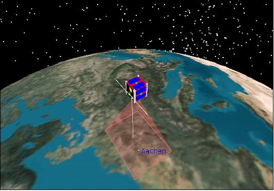
COMPASS-1 is a CubeSat imaging project of the University of Applied Science at Aachen, Germany (FH Aachen) - initiated in late of 2003 by a team of eight students taking an astronautical engineering course (the COMPASS team includes students of several engineering departments and also faculty members). The motivation was (and still is) to gain experience and a fresh approach into all aspects of spacecraft system engineering and operations, i.e. to put the lectures into real-world practice. The CubeSat concept represented a feasible and economical approach in this venture, using COTS (Commercial-of-the-shelf) components wherever possible. Also, the mission objective was set on remote sensing demonstrations because such a type of mission tolerates more lenient pointing requirements on the picosatellite attitude control, as well as on the availability of communication and power supply services. 1) 2) 3) 4)
Spacecraft
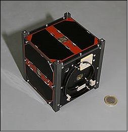
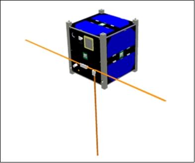
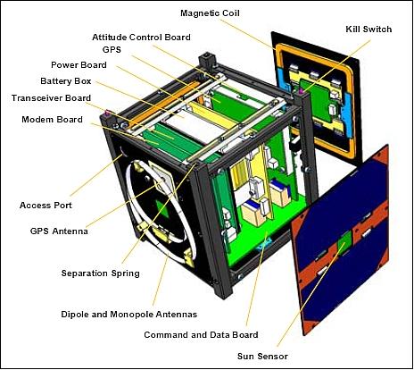
The picosatellite employs the standard CubeSat structure of size 10 cm x 10 cm 10 cm with a mass of ≤ 1 kg. The structure is highly modular for easy assembly. Of particular importance are the mechanisms to deploy the UHF/VHF antennas after deployment and to close/open the power circuit of the satellite.
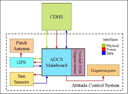
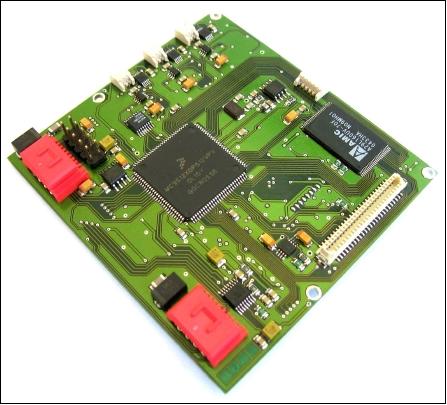
ADCS (Attitude Determination and Control Subsystem)
The spacecraft is 3-axis stabilized. The ADCS is using active magnetic coils for attitude control. The spacecraft's attitude is derived from measurements of the suns' position and the instantaneous geomagnetic flux density. This attitude information is then fed into a regulator which drives a set of three mutually perpendicular electromagnetic coils. These magnetorquers generate a magnetic dipole which interacts with the geomagnetic field to produce the control torque necessary to maintain the satellite's nominal nadir alignment. 5) 6)
Magnetometers
The measurement of the local magnetic field vector is being done with magnetometers using the HMC6352 digital compass developed and distributed by Honeywell. The sun sensors employ MOEMS (Micro-Opto-Electro-Mechanical System) technology; they have been developed at DTU (Denmark Technical University).
CDHS (Communications and Data Handling Subsystem)
The CDHS uses microprocessors to process all requests by the onboard subsystems and to store the data in a non-volatile memory (32 MByte of Flash memory). The onboard data are composed of the imagery captured by the camera module that is connected and controlled by this subsystem and from the housekeeping data being requested from the other subsystems. There are 4 microprocessors onboard providing a distributed computing environment.
EPS (Electric Power Subsystem)
The EPS employs face-mounted triple-junction GaAs solar cells for power generation. Lithium-polymer cells are being used to store excessive energy during sunlight and to supply the subsystem during the eclipse phases of the orbit. The EPS provides power management to secure the battery power and to detects and correct failures caused by Single-Event Effects. Active thermal control is realized with a heater placed at the batteries. The available power consumption is 2 W (max) and 1 W average). The battery storage capacity is 2.4 Ah.
RF Communications
The satellite is being controlled from a UHF/VHF ground station through commands, which are sent in reliable DTMF (Dual-tone multi-frequency) pulse tones. Data packets containing images and housekeeping data are being downlinked from the satellite using the AX.25 protocol. The system periodically emits a beacon signal with the satellite signature and basic system information data. The UHF downlink frequency is 437.405 MHz, while the beacon frequency is 437.275 MHz in CW (Continuous Wave) mode.
Ground Control
Two ground stations are being used for satellite operations. The primary station is located in Aachen (FH Aachen Campus), Germany and the secondary station is in Tainan, Taiwan. Both stations use a 2 m dish antenna for the 70 cm frequency band.
Spacecraft stabilization | 3-axis stabilized using magnetic torquers |
Attitude determination | Use of sun sensors and magnetometers |
Spacecraft pointing accuracy | ± 8º |
RF communications | - UHF/VHF downlink/uplink (UHF frequency at 437.405 MHz) |
Beacon downlink | - Periodically transmitted every ~3 minutes (every ~8 minutes during power safe) - Frequency: 437.275 MHz CW |
Spacecraft power | - Use of triple-junction GaAs solar cells |
Launch
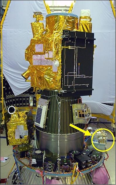
A launch of COMPASS-1 as a secondary payload to the CartoSat-2A primary spacecraft took place on April 28, 2008. The launch site was SDSC (Satish Dhawan Space Centre), the SHAR launch range (Sriharikota, India) of ISRO.
The launch of secondary payloads was being shared by IMS-1 (Indian Microsatellite-1) of ISRO with the following CubeSats or nanosatellites: CanX-2 of UTIAS/SFL, Toronto, Canada; AAUSat-2 of Aalborg University, Denmark; COMPASS-1 of the University of Applied Science, Aachen, Germany; Delfi-C3 of the Technical University of Delft, The Netherlands; SEEDS of Nihon University, Japan; CUTE-1.7+APD-2 CubeSat of the Tokyo Institute of Technology (TITech); NTS (Nanosatellite for Tracking of Ships) of COM DEV / UTIAS/SFL, Toronto, Canada; Rubin-8-AIS an experimental space technology mission of OHB-System, Bremen, Germany.
The launch of the 8 CubSat or nanosatellite payloads was executed under a commercial contract between the University of Toronto, COSMOS International (a company of the OHB Fuchs Gruppe, Bremen, Germany), and the Antrix Corporation of Bangalore, India (the latter is the commercial arm of ISRO). - Six custom-built XPOD (eXperimental Push Out Deployer) units were provided by UTIAS/SFL to deploy all smallsats - except the CUTE-1.7+APD-2 (3.5 kg) double cube of TITech which used its own TSD deployer system.
Orbit
Sun-synchronous near-circular orbit, altitude = 635 km, inclination = 97.94º, the period is 97.4 minutes, the local time on the descending node (LTDN) is at 9:30 hours.
Mission Status
• The COMPASS-1 mission was retired on March 3, 2012. 7)
• COMPASS-1 CubeSat is operating nominally in 2011 (Ref. 8).
• COMPASS-1 is operating nominally in July 2010. The project receives on a daily basis HK data and beacon data. 8)
• The bus functions of COMPASS-1 continued to operate nominally through 2009. In summary, the mission is considered a success (in particular the experience of operation, the troubleshooting and the learning effect by all involved), although not all objectives could be accomplished (Ref. 9).
• The GPS receiver was activated several times. The receiver initializes and operates without malfunction but fails to establish contact to any GPS satellites. The problem was traced to an improper integration of the patch antenna at the front panel that, combined with a mismatch in the antenna connection, causes a severe limitation of the antennas field of view such that a link cannot be established.
• Several images from the on-board camera could be received. However, a faulty exposure adjustment yielded images of inferior quality.
• In October and November 2008, sporadic resets of the spacecraft occurred again. Both cases were taken care of immediately and did not lead to a critical depletion of battery capacity.
• In early August 2008, a serious problem arouse which was triggered by a hard reset of the satellite system. The satellite then entered emergency mode and remained there for several days. A major weak point of the system was revealed, because it was not possible to reset the heater activation during emergency mode. The only chance of rescue was to catch the short moment when the satellite came out from eclipse (permitting a switch into nominal mode) and before the heater would force the system again back into emergency mode.
With lots of help from the amateur radio community, an almost dead satellite had been brought back into nominal operation. From end of August 2008 onwards, the satellite operation continued smoothly.
• A partnership between the Aachen ground station and the Ham radio community ensured the continuous progress of the mission, which might have been led to a premature end otherwise.
• Initial problems with both ground stations (data reception and transmission) were a reason that the spacecraft couldn't be commanded during the first six weeks after launch. During this period, the beacons were monitored to observe the satellite’s well-being in orbit, while at the same time the primary ground station was being repaired. 9) 10)
• The first contact with the COMPASS-1 picosatellite was established by a radio amateur station in California. Later the ground station at FH Aachen was also able to receive housekeeping telemetry from its spacecraft.
Sensor Complement
Optical Camera
A staring CMOS color camera is being used for snapshot imagery. The module consists of a lens system and a light sensitive CMOS detector array which generates VGA images with a resolution of 640 by 480 pixels (detector size). A data quantization of 8 bit is provided. The FOV (Field of View) is 53º providing a target size of 416 km x 380 km from an orbital altitude of 635 km. Each image has a size of about 300 kByte.
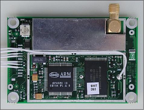
GPS Miniature Receiver
The Phoenix GPS receiver of DLR is being used for orbit determination. The instrument is a 12-channel single-frequency GPS receiver with modified software to cope with the high-dynamics environment of a picosatellite in LEO. The receiver has a size of 50 mm x 70 mm, a mass of 22 gram, and a power consumption of 0.8 W. 11) 12)
In case of very tight power budgets, the receiver can also be operated intermittently. A rapid signal acquisition is assured by aiding the receiver with approximate orbital information in the form of NORAD twoline elements. Critical data like GPS almanac and broadcast ephemerides as well as user orbit parameters can be stored in a buffered non-volatile memory and used to initialize the receiver after a reboot. Likewise the current time is maintained by a real-time clock during deactivation of the main power supply. This allows a hot start of the receiver with typical times-to-first-fix (TTFF) of < 30 s. The Phoenix receiver has been tuned for highly accurate tracking, navigation and timing.
References
1) http://www.raumfahrt.fh-aachen.de/compass-1/home.htm
2) “COMPASS-1 brochure, 2005, URL: http://www.raumfahrt.fh-aachen.de/compass-1/download/brochure_COMPASS-1.pdf
3) A. Scholz, J. Giesselmann, C. Duda, “CubeSat Technical Aspects,” 55th International Astronautical Congress of the International Astronautical Federation, the International Academy of Astronautics, and the International Institute of Space Law, Vancouver, Canada, Oct. 4-8, 2004, IAC-04-P.5.B.07
4) A. Scholz, “ COMPASS-1 hands-on experience for the space engineers of tomorrow,” Proceedings of RAST' 03 (Recent Advances in Space Technologies, 2003), Istanbul, Turkey, Nov. 20-22, 2003
5) A. Aydinlioglu, M. Hammer, “COMPASS-1 Pico Satellite: Magnetic Coils for Attitude Control,” Proceedings of RAST 2005 (Recent Advances in Space Technology), Istanbul, Turkey, June 9-11,2005
6) Jens Giesselmann, “Development of an Active Magnetic Attitude Determination and Control System for Picosatellites on highly inclined circular Low Earth Orbits,” Thesis, June 2006, URL: http://adt.lib.rmit.edu.au/adt/uploads/approved/adt-VIT20070514.162516/public/02whole.pdf
7) Information provided by Bernd Dachwald of FH Aachen, Germany.
8) Information received on July 22, 2010 by Felix König of FH Aachen, Germany.
9) Artur Scholz, Wilfried Ley, Bernd Dachwald, Engelbert Plescher, Jiun-Jih Miau, Jyh-Ching Juang, “Flight Results of the COMPASS-1 Picosatellite Mission,” Proceedings of the 60th IAC (International Astronautical Congress), Daejeon, Korea, Oct. 12-16, 2009, IAC-09.B4.3.10
10) Artur Scholz, Felix König, Steve Fröhlich, Johannes Piepenbrock, “Flight Results of the COMPASS-1 Mission,” March 8, 2009, http://www.raumfahrt.fh-aachen.de/compass-1/download/COMPASS-1%20Flight%20Results.pdf
11) http://www.weblab.dlr.de/rbrt/GpsNav/Phoenix/Phoenix.html
12) O. Montenbruck, B. Nortier, S. Mostert, “A Miniature GPS Receiver for Precise Orbit Determination of the SunSat 2004 Micro-Satellite,” ION NTM (National Technical Meeting) 2004, San Diego, CA, USA, Jan. 26-28, 2004
The information compiled and edited in this article was provided by Herbert J. Kramer from his documentation of: ”Observation of the Earth and Its Environment: Survey of Missions and Sensors” (Springer Verlag) as well as many other sources after the publication of the 4th edition in 2002. - Comments and corrections to this article are always welcome for further updates (eoportal@symbios.space).