Colony-1 CubeSats of NRO
EO
Mission complete
NRO
Quick facts
Overview
| Mission type | EO |
| Agency | NRO |
| Mission status | Mission complete |
| Launch date | 08 Dec 2010 |
| End of life date | 16 Jan 2011 |
| CEOS EO Handbook | See Colony-1 CubeSats of NRO summary |
Colony-1 CubeSats of NRO
Overview
In 2009, AS&T (Advanced Systems and Technology Directorate) of NRO (National Reconnaissance Office) started the Weather Colony Program to demonstrate the feasibility of placing payloads on CubeSats to accelerate technology evaluations, address underserved missions, field capabilities with reduced cost, and tighten schedules relative to larger satellite acquisitions. 1)
AS&T collaborated with the Office of Naval Research to identify space weather mission areas for integration on CubeSats. Subsequently, AS&T awarded a contract to the NRL (Naval Research Laboratory), in April 2009, to identify and integrate small, lightweight, and low-power space weather sensors on CubeSats to monitor solar radiation, changes in the Earth’s magnetic field, and other space weather phenomenon.
The AFWA (Air Force Weather Agency) at Offutt Air Force Base, Nebraska provides the NRO with space environment warnings and advisories, as well as space environment analysis and forecast specifications from the GAIM (Global Assimilation of Ionospheric Measurements) model. The AFWA is working to improve data assimilation into GAIM and forecast capabilities by transitioning from a statistic-based to a physics-based approach by 2013.
The Weather Colony Program provides an alternative for AFSPC (Air Force Space Command) to close the gap in coverage without incurring the costs of more expensive, larger platforms. AFSPC plans to complete an analysis of program alternatives, including the potential role of CubeSats.
The first two NRO Weather Colony CubeSats will have sensors to measure the radiation, electron density, and ion composition of the space environment. They will also have the ability to measure the charge on the spacecraft as it passes though the ionosphere.
Some background of the Colony program of NRO 2)
Since 2007, the NRO (National Reconnaissance Office) has made a significant commitment to the CubeSat approach - to enhance R&D (Research and Development) activities. Smallsats, CubeSats in particular, allow the NRO to perform research and development at a rapid pace, enabling us to mature a broad spectrum of new technologies for future systems while accepting higher levels of risk. Technology maturation can be conducted quickly and economically using CubeSats, due to their low cost, rapid development cycle, and the potential for more frequent launch opportunities. CubeSats provide the opportunity to keep up with Moore’s Law, advancing on a six to twelve month development cycle. On-orbit testing provides bigger systems with higher TRL (Technology Readiness Level) components, lowering program developmental risks and cost growth.
Examples of near-term technologies to be proven on CubeSats include advanced multi-junction solar cells and carbon nanotube batteries. These technologies promise to improve overall size, weight, and power of future systems. Recent investments in CubeSats provide the NRO access to innovative methods to rapidly exploit technologies to address changing needs, while offering a new business model for adapting new technologies to tackle hard problems in the future.
In 2010, NRO has 12 nanosatellites being built with a goal of building and flying as many as 50 within the next three years. A significant part of the near-term investment focuses on maturing the CubeSat bus components needed to provide the foundation for future experiments under an effort NRO calls Colony. By providing and evolving a “common” CubeSat bus, Colony allows designers to focus on developing experiments and demonstrating ConOps (Concepts of Operation) rather than re-inventing supporting subsystems (e.g., structures, power systems, ADCS (Attitude Determination and Control Subsystem ), processing, thermal, and communications) which has been common practice with many of the purpose-built CubeSats flown to date. Thus, the Colony effort has established a standard that NRO can use to develop technologies and mission concepts at lower cost by providing a documented standard vehicle that can be built using quantity purchased parts and assembled by people with experience building other identical craft.
Because (AS&T) is chartered to seed technologies for all of the NRO, the needs for a low-cost, high-rate demonstration capability is acute, and the non-productive NRE (Non-Recurring Engineering ) costs of the bus proportionally higher. While a traditional mission-driven organization would develop a vehicle optimized for its mission to host a specific type of sensor, AS&T needs a vehicle to perform its mission to demonstrate a wide range of basic technologies on the same one- to three-year R&D cycle as the current technology development efforts.
By managing space R&D projects as a portfolio of diverse capabilities, the costs of designing, building, and testing non-payload subsystems become obvious not only by their dollar cost but, also by the lost opportunities to fund other technologies. Being an organization with the opportunity and interest to fund a range of technologies, NRO has been especially hampered by these costs over the years.
The current NRO Colony program is set to build 10 CubeSats every 12 months. The payloads for these spacecraft are chosen each year, allowing for the maximum opportunity for new technologies to address new requirements. Additionally, the spacecraft bus contract is intended to be re-competed every 24 months. This allows for new capabilities and advances in satellite bus technologies to be rapidly incorporated.
Small satellites leverage commercial technologies in a much more exciting way than traditional programs. For example, the batteries that are the primary power source for several CubeSats on orbit are exactly the same as the batteries used in Apple iPods today. Leveraging these evolving technologies in a large, complex satellite program is inconceivable due to the time and risk involved in incorporating new, non-space qualified parts.
The NRO CubeSats are allowing new technology to gain flight heritage that might take years to earn on traditional satellite programs. The NRO is pursuing several near term research and development activities centered around small satellites. Technologies such as solar cells, batteries, commercial processors and radios are being integrated as CubeSat payloads and will be demonstrated on-orbit. Small satellites can accelerate these development activities by providing rapid feedback to developers, allowing them to refine their processes. The mature, proven technologies can then be transitioned to larger platforms, allowing NRO to keep pace with national needs.
Two examples of such technologies are the Gravity-gradient boom and the modular attitude control system.
1) NRO is developing a lightweight boom with integrated solar cells to greatly increase available power. The boom will also provide low cost and completely passive gravity-gradient attitude stabilization for a two-segment CubeSat spacecraft. This added capability will increase system power by a factor of 5 and will enable higher power payloads to be demonstrated on orbit. This approach uses passive strain energy for deployment, which could also be adapted to larger spacecraft systems.
2) Another example is a low cost precision pointing CMG (Control Moment Gyro) system. This attitude control system, based on a redundant four gimbal CMG configuration, will enable future CubeSat systems to actively maintain peak tracking and sensor positioning for more demanding demonstrations. The modular architecture enables the system to be easily retrofitted within the CubeSat framework.
Colony-1 (also spelled as Colony-I) was NRL's (Naval Research Laboratory) first attempt at using CubeSats to send, receive, store, and forward data to meet current operational needs. Their Colony-1 mission was a proof-of-concept to use CubeSats as technology demonstrators and remote, automated, and COTS hardware and GOTS (Government Off-the-Shelf) software based ground stations to complete the mission.
Spacecraft
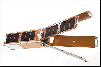
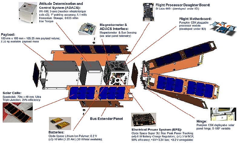
The NRL Colony-1 nanosatellites (3U form factor CubeSat), referred to as QbX-1 (CubeSat Experiment-1) and QbX-2, are based on the Pumpkin XS-25a CubeSat bus. The XS-25a provides a 3-axis stabilized platform, hinged, deployable solar panels with a Clyde Space electrical power and battery storage system, flight control software, and a payload bay.
The two nanosatellites were built by Pumpkin Inc. of San Francisco, CA and provided to the NRL by the National Reconnaissance Office's (NRO's) Colony Program Office. Each QbX nanosatellite has a mass of ~4.5 kg, a size of 10 cm x 10 cm x 30 cm, and a power generation capability of ~ 10 W (max) with the extension of the panel-based EPS. This is the first flight of the Pumpkin-built Colony I spacecraft bus and is being used to evaluate the performance of the vehicle as a platform for experimentation. 4)
The spacecraft structure is composed of a compartmented aluminum frame housing the bus components, the ADCS (Attitude Determination and Control Subsystem), and a separable payload section. The 3U structure is divided into (approximately) ¾U for the bus electronic components, ¾U for the ACS, and 1.5U for the payload components. 5)
The spacecraft attitude is controlled by, and operates in, a novel "Space Dart" mode (aerodynamic fins were employed to provide correcting torques for velocity-vector pointing). 6) Due to the low orbit (300 km) atmospheric drag provides a stabilization torque that, used with reaction wheels and torque coils, provides stable pointing to within five degrees of nadir throughout the orbit.
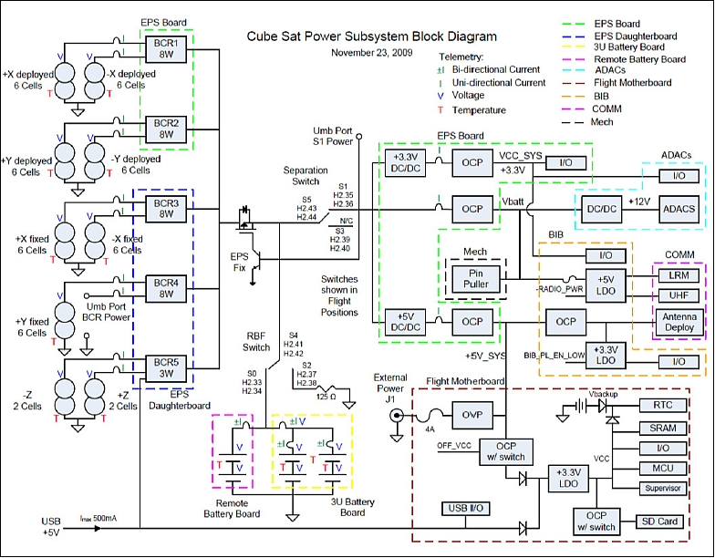
EPS (Electrical Power Subsystem)
The EPS was the 3U Deployable CubeSat power system from Clyde Space. Primary power was provided by seven solar panels, 3 body-mounted and 4 deployable, with 6 solar cells each and two additional solar panels with 2 solar cells each. A configuration of 2 series, 3 parallel Li-Ion pouch cells provided secondary power. The Emcore ATJ (Advanced Triple-Junction) cells used measured 70 mm x 40 mm and were ~27% efficient (BOL). The deployable panels served a dual purpose in that at the relatively low altitude of our orbit (300 km nominal) the resultant atmospheric drag made 3-axis control of the spacecraft difficult at best. The novel solution of NRL was to utilize the drag to orient the spacecraft towards its lowest energy state – the so called “space dart” configuration (Figure 1).
Five independent peak power trackers regulated the solar array power and charged the battery. The EPS provided both regulated and unregulated power to the spacecraft load. In this paper, the flight performance of the EPS will be reviewed. Flight data on the battery and solar arrays are compared with ground test data and a power system model. Additionally, observations from integration and test will be shared to provide a complete picture of using this EPS over the course of a program.
ADCS (Attitude Determination and Control Subsystem)
The ADCS was from MAI (Maryland Aerospace, Inc.), formerly IntelliTech Microsystems, Inc. – IMI. IMI-100 provides miniature reaction wheels, torque coils for momentum dumping, and an external magnetometer for 3-axis knowledge and control to better than 1° pointing.
C&DH (Command and Data Handling) Subsystem
Within the bus section, the C&DH, mass storage, and power switching functions are performed by the FMB (Flight Mother Board). Utilizing an open and extensible architecture, the FMB accepts numerous types of PPM (Pluggable Processor Modules). Developed in conjunction with QbX by Pumpkin, an 8051-based PPM was selected to allow substantive software reuse by NRL. - NRL provided also the flight software for Colony I, ported from previous and ongoing NRL programs to the Pumpkin Colony I processor. This included also an onboard scheduler for routine vehicle control and operation.
RF communications: NRL developed the TT&C (Tracking, Telemetry & Command) subsystem providing reliable two-way data transfers.
Launch
The QbX-1 and QbX-2 nanosatellites were launched as secondary payloads on Dec. 8, 2010. SpaceX launched the Dragon-C1 space capsule (primary payload) into orbit on the Falcon-9 spacecraft. The launch site was the AFS/SLC (Air Force Station/Space Launch Complex) 40 at Cape Canaveral, FL. It was also the first demonstration flight for NASA's COTS (Commercial Orbital Transportation Services) program for which SpaceX was selected. 7)
The primary mission objectives were to test the orbital maneuvering and reentry of the Dragon capsule. The mission also aimed to test fixes to the Falcon-9 rocket, particularly the unplanned roll of the first stage that occurred during Flight 1.
Secondary payloads: The Falcon-9 carried a total of 8 nanosatellites and/or CubeSats to orbit, all of which were deployed from P-PODs onboard the second stage of Falcon-9.
• SMDC-ONE (Space & Missile Defense Command-Operational Nanosatellite Effect), a 3U CubeSat with a mass of ~4.5 kg.
• Two Colony-1 nanosatellites (each a 3U CubeSat), namely QbX-1 and QbX-2.
• Two P-PODs contained four 1.5U satellites from LANL (Los Alamos National Laboratory) called Perseus.
• The last P-POD contained a3U CubeSat known as Mayflower-Caerus. The CubeSat was built as a joint mission. One unit of the 3U CubeSat was Caerus from the University of Southern California. The other two units of Mayflower were from Novaworks of Northrop Grumman. -The Mayflower-Caerus nanosatellite featured an experimental propulsion system and eight extra solar panels that deploy as two arrays, the CubeSat downlinks used the UHF band to amateur radio stations.
Orbit
Non-sun-synchronous orbit, low altitude of ~ 300 km apogee x 275 km perigee (due to the requirement of the primary payload), inclination = 34.5º, period = 88.1 minutes. - The Dragon space capsule was retrieved successfully after two orbits in the Pacific Ocean.
Mission Status
All secondary payloads had an expected short mission life of ~ 30 days due to the low deployment orbit provided by the primary mission resulting in a relatively fast natural decay orbit.
• The QbX-1 nanosatellite was on orbit for 29 days and reentered Earth's atmosphere on January 6, 2011 (after 468 orbits).
• The QbX-2 nanosatellite was on orbit for 39 days and reentered Earth's atmosphere on January, 16, 2011
• The successful deployment of the solar arrays and antennas of QbX-1 and QbX-2 was verified shortly after launch.
Colony I was a successful mission that proved the concept of building CubeSats, testing them, and then flying them in a short amount of time. The program provided insight and operational experience about satellite design, CubeSat ride share problems and operations, and on-orbit CubeSat operations.
Sensor Complement
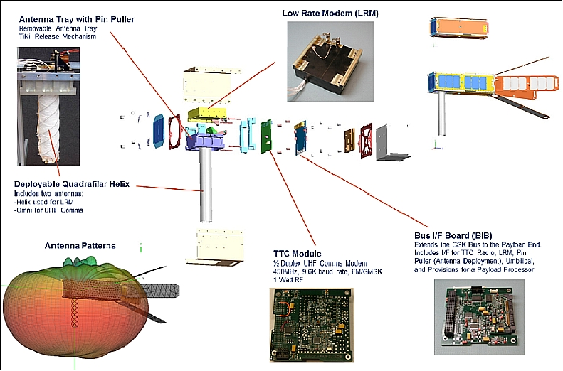
The payload consisted of an extendible antenna, a modem, and a radio. The QbX satellites were complex enough to thoroughly test the ground station command and control functions. The payload featured custom built BIB (Bus to Payload Interface Card ), a custom-built, half-duplex TT&C radio, and experimental LRM (Low Rate Modem) used for the primary communications experiments, and a custom-build deployable dual-antenna with a central UHF (TT&C) monopole surrounded by a quadrifiler helix antenna.
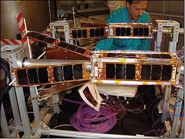
NRL’s Spacecraft Engineering Department engineers tested and integrated the nanosatellites before launch, and communicated successfully with them after on-orbit deployment. The TT&C (Tracking, Telemetry, and Command) radio was fully functional, providing reliable two-way data transfers. The flight software provided an onboard scheduler for routine vehicle control and operation. All deployments, including solar arrays and antennas, were verified shortly after launch. Commands were sent to the satellites and data profiles were received from the onboard systems. The spacecraft ADCS operated in a novel “space dart” mode, so called because of the shape of the deployed satellite. In this mode, atmospheric drag in the low orbit (300 km) provides a stabilization torque that, augmented with a single momentum bias wheel for stiffness and three torque coils for magnetic damping, provides stable pointing to within five degrees of nadir throughout the orbit. The hybrid passive/active attitude control system required no attitude sensing other than measurement of the local magnetic field using a three-axis magnetometer.
Ground Segment
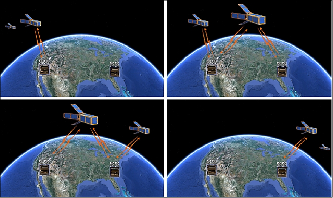
A major NRO objective was to make initial tests with MC3 (Mobile CubeSat Command and Control), a distributed ground station system for the Colony program. NRL's MC3 is a low cost, mobile, instant ground station system that can be easily networked over the Internet to increase the operations array.
The Colony I MC3 system consisted primarily of COTS (Commercial-off-the Shelf) hardware ordered from amateur radio suppliers like Yaesu, M2 antennas, and ICOM radios. The heart of the Colony I MC3 was NRL's CGA (Common Ground Architecture) laptop controlling the ground station. 8) 9) 10)
The CGA software controls all aspects of the ground station and satellite operations. During the development and testing of the Colony I satellite the MC3 ground station hardware and CGA software were used to control, test, and develop the satellite operating system. CGA allows for the development of flight hardware on actual ground station hardware using the same commands, data paths, and operations as the satellite would use once on orbit. By using the same hardware and software for development, testing, and operations, risks associated with using different test gear from actual flight gear are eliminated because the hardware and software do not change from development to flight. For communicating with a satellite, CGA takes the ephemeris data of the tracked satellite, tunes the radios to the appropriate frequencies, aligns the antenna to track the satellite during the pass, transmits all queued commands, and receives all data from the satellite.
CGA forwards the data to any desired recipient and alerts engineers if the satellite is not operating at expected levels. With proper programming CGA could even analyze bus and payload data. When properly configured a MC3 ground station can operate completely unmanned; if there are any problems that normal troubleshooting procedures cannot solve, the MC3 will e-mail, text, and phone support engineers to alert them to the trouble.
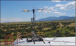
The MC3 system comes in one computer rack and uses two portable antennas for easy installation at any participating facility. Figures 6 and 7 show the Colony I MC3 computer rack and one of the antenna masts.
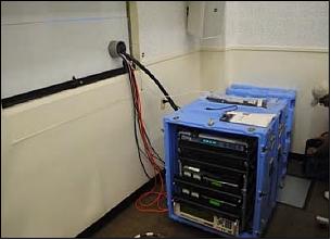
The MC3 comprises a Linux-based laptop PC, hosting the CGA system with a USB/UART interface to the hardware listed in Table 1. The MC3 uses mostly commercial hardware to provide the CubeSat uplink and downlink communications and data transfer. Hardware setup and operation is accomplished remotely via CGA interface from the central operations facility.
Quantity | Function | Manufacturer | Model | Notes |
2 | UHF Transceiver | ICOM | IC-910H |
|
1 | UHF Modem Control | ICOM | CT-17 |
|
2 | UHF Modulator/Demodulator | Custom | I2K |
|
2 | Antenna Controller Interface | Yaesu | GS-232B | Rotor computer interface |
1 | GPS Network Time Server | Symmetricom | S250 |
|
1 | Uninterruptible Power Supply | APC | Back-UPS RS, 1500 VA |
|
1 | Computer | Dell | M4400 | Laptop |
1 | Enclosure | Hardigg |
| ½ rack with removable front/back |
2 | Az/El antenna rotator controller | Yaesu | G-5500 |
|
1 | 8 port 10/100 Ethernet switch | Cisco | SRW208P |
|
1 | VPN Firewall | GTA | GB-800e |
|
2 | LNA | ICOM |
|
|
2 | UHF Antenna | M2 |
|
|
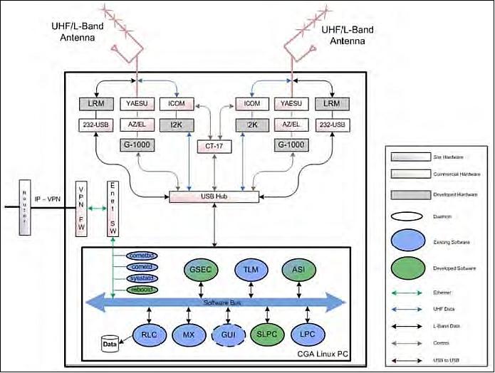
The MC3 interfaces with top-level architectures for satellite operations using dual antennas in a portable unit that can be installed anywhere as needed. It includes appropriate levels of security and can be controlled remotely or locally, where locally the operator will have priority. It is connected via a VPS (Virtual Private Server) to a central node in Blossom Point.
The Colony I basic MC3 architecture and operational diagram is shown in Figure 9.
The MC3 units used were produced specifically to support CubeSat communications. The required data rate for the downlink is 1 kbit/s. In order to expand the usefulness of future systems of many diverse small satellites, increased data rates are needed. If a standardized RF communication link were employed for all CubeSat missions, the cost effectiveness of MC3 use can be maximized. The Air Force Satellite Control Network sites are distributed for worldwide coverage and have a common RF front end that uses the DoD SGLS (Space-to-Ground Link Subsystem) protocol. As of now, there is no RF standard for CubeSats. Most use proprietary systems.
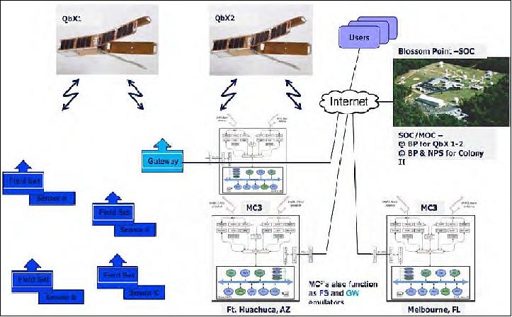
Mission Operations
The Colony I mission was controlled from the SOC (Satellite Operations Center) at BPTF (Blossom Point Test Facility), located near LaPlata, MD. SOC was using the ground stations in Melbourne, Florida, and Fort Huachuca, Arizona. The mission tested sending information from remote sensors to users via the QbX-1 and QbX-2 to the Colony I MC3 to the Internet. The CGA implementation in MC3 allowed for the ground stations to be unmanned 24/7 and only signal for assistance if a ground engineer was needed to resolve a problem.
References
1) Daniel Edwards, “NRO Weather Colony Program,” Space Sentinel, Vol. 2, No 2, 2010, URL: http://www.nro.gov/news/sss/2010/sss-2010-02.pdf
2) David Shultz, Rebecca A. Unruh, David C. Williamson, John Anttonen, “Colony: A New Business Model for Research and Development,” Proceedings of the 24th Annual AIAA/USU Conference on Small Satellites, Logan, UT, USA, Aug. 9-12, 2010, paper: SSC10-IV-2
3) Andrew E. Kalman, “Pumpkin’s Colony I CubeSat Bus: Past, Present and Future,” GAINSTAM (Government And Industry Nano-Satellite Technology And Mission) Workshop, Nov. 4-5, 2009, Huntington, Beach, CA, USA, URL: http://www.cubesatkit.com/docs/press/Pumpkin_GAINSTAM_2009.pdf
4) Daniel Parry, “NRL Launches Nano-Satellite Experimental Platforms,” NRL News Release 160-10r, Dec. 17, 2010, URL: http://www.nrl.navy.mil/media/news-releases/2010/nrl-launches-nanosatellite-experimental-platforms
5) Stephen Arnold, James Armstrong, Clark Person, Michael Tietz, “QbX - The CubeSat Experiment,” Proceedings of the 26th Annual AIAA/USU Conference on Small Satellites, Logan, Utah, USA, August 13-16, 2012, paper: SSC12-XI-4
6) James Armstrong, Craig Casey, Glenn Creamer, Gilbert Dutchover, “Pointing Control for Low Altitude Triple Cubesat Space Darts,” Proceedings of the 23nd Annual AIAA/USU Conference on Small Satellites, Logan, UT, USA, Aug. 10-13, 2009, paper: SSC09-X-4
7) William Graham,“SpaceX launches Falcon 9 – Debut Dragon completes COTS demo,” Dec. 8, 2010, URL: http://www.nasaspaceflight.com/2010/12/live-spacex-launch-falcon-9-dragon-cots-demo/
8) Robert C. Griffith, “Mobile CubeSat Command and Control,” NPS Thesis, Sept. 2011, URL: https://calhoun.nps.edu/handle/10945/5591
9) Gregory C. Morrison, “Mobile CubeSat Command and Control: Assembly and Lessons Learned,” NPS Thesis, Sept. 2011, URL: http://www.dtic.mil/dtic/tr/fulltext/u2/a551939.pdf
10) Trevor Sorensen, Bruce Yost, Joan Differding, Eric Pilger, Miguel Nunes, “Plug and Play Mission Operations,” Proceedings of the 2012 IEEE Aerospace Conference, Big Sky, Montana, USA, March 3-10, 2012
The information compiled and edited in this article was provided by Herbert J. Kramer from his documentation of: ”Observation of the Earth and Its Environment: Survey of Missions and Sensors” (Springer Verlag) as well as many other sources after the publication of the 4th edition in 2002. - Comments and corrections to this article are always welcome for further updates.(eoportal@symbios.space)