CFOSAT (Chinese-French Oceanography Satellite)
EO
Ocean
CNES
Operational (nominal)
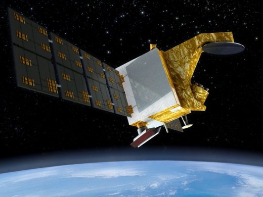
Launched in October 2018, Chinese-French Oceanic SATellite (CFOSAT) is a radar satellite operated collaboratively by the Centre National d’Etudes Spatiales (CNES) and the Chinese National Space Administration (CNSA). CFOSAT internationally monitors the wind and waves of the ocean surface to advance our knowledge and models of them, thus improving our forecasting ability.
Quick facts
Overview
| Mission type | EO |
| Agency | CNES, CNSA |
| Mission status | Operational (nominal) |
| Launch date | 29 Oct 2018 |
| Measurement domain | Ocean |
| Measurement category | Ocean surface winds, Ocean wave height and spectrum |
| Measurement detailed | Wind vector over sea surface (horizontal), Significant wave height, Dominant wave direction, Dominant wave period, Wave directional energy frequency spectrum |
| Instruments | SCAT, SWIM |
| Instrument type | Scatterometers |
| CEOS EO Handbook | See CFOSAT (Chinese-French Oceanography Satellite) summary |
Summary
Mission Capabilities
CFOSAT is equipped with two radar scatterometers, the Wind SCATerometer (SCAT) and the Surface Waves Investigation and Monitoring (SWIM). SCAT exclusively monitors wind speed magnitude and direction, whereas SWIM monitors wind speed direction, wave height, wave propagation direction, and the wavelength of waves.
Performance Specifications
SCAT is a rotating fan beam scatterometer with a centre frequency of 13.256 GHz (Ku-band). It observes over a swath of more than 1000 km with a spatial resolution of 50 km. The wind speed magnitude measurements have an accuracy of 2 m/s or 10% (whichever is larger), and the direction measurements have an accuracy of 20°.
SWIM has a centre frequency of 13.575 GHz and observes over a swath of 180 km with a spatial resolution of 18 km. It can measure wind speed magnitude with an accuracy of 2 m/s or 10% (whichever is larger), wave height with an accuracy of 0.5 m or 10% (whichever is larger). The wave propagation direction has an ambiguity of 180° and an accuracy of 15°, and wavelength has an accuracy of 20%. SWIM is able to monitor such characteristics by having six rotating beams, each with a different angle between the nadir and 10°.
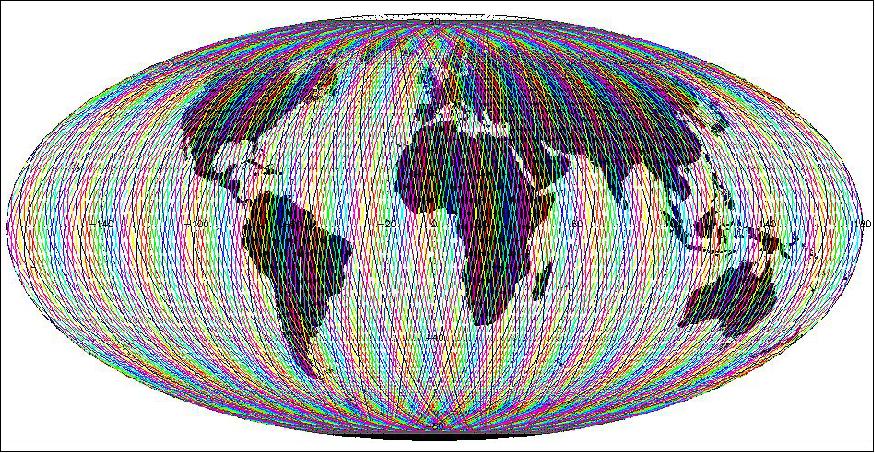
CFOSAT undertakes a sun-synchronous orbit with an altitude of 519 km, and an inclination of 97°. SCAT will provide global wind measurements within 3 days, whereas SWIM will provide global wave measurements within 13 days.
Space and Hardware Components
Weighing 650 kg, CFOSAT was launched onboard a Chinese-built Long March 2C launch vehicle from the Jiuquan Satellite Launch Centre (JSLC) in China.
CFOSAT has various subsystems onboard: ACOS (Attitude Control and Orbit control Subsystem) which provides three-axis stabilisation, EPS (Electrical Power Subsystem) which controls energy generation and storage, and radio communications. Radio communications for Telemetry, Tracking, and Command (TT&C) are performed via S-band frequencies with a downlink data rate of 16.384 kbit/s and an uplink rate of 2 kbit/s.
Despite the design life of three years, CFOSAT is still operational.
CFOSAT (Chinese-French Oceanography Satellite)
Spacecraft Launch Mission Status Sensor Complement Ground Segment References
CFOSAT is a joint mission of the Chinese (CNSA) and French (CNES) space agencies with the goal to monitor the ocean surface winds and waves and to provide information on related ocean and atmospheric science and applications. The primary objective of CFOSAT is to monitor on a global scale the wind and waves at the ocean surface in order to improve: 1) 2) 3) 4) 5)
• The wind and wave forecast for marine meteorology (including severe events)
• The ocean dynamics modeling and prediction
• Our knowledge of climate variability
• Fundamental knowledge on surface processes linked to wind and waves.
An operational demonstration objective of CFOSAT is to provide observations over the ocean in near-real-time for assimilation in meteorological and wave forecast models. Wind and wave products must be available in operational centers within 3 hours after acquisition.
CFOSAT will also be used to complement other satellite missions for the estimation of land surface parameters (in particular soil moisture and soil roughness), and polar ice sheet characteristics.
On March 26, 2014, CNES President Jean-Yves Le Gall and Xu Dazhe, Administrator of CNSA (China National Space Administration), signed an agreement aimed at achieving closer cooperation between France and China in oceanography and astrophysics. The signing took place in Paris in the presence of President François Hollande and his Chinese counterpart, Xi Jinping. The agreement defines the terms governing the cooperation between France and China in oceanography and astrophysics through the joint development of the CFOSAT satellite to study ocean surface wind and waves and the SVOM (Space Variable Objects Monitor) satellite to study gamma-ray bursts. CFOSAT is a science mission designed to study ocean surface wind and wave conditions with a view to improving forecasts for marine meteorology and knowledge of climate variability. CFOSAT will carry two main instruments: SWIM (Surface Waves Investigation and Monitoring), a wave scatterometer supplied by CNES, and SCAT, a wind-field scatterometer supplied by CNSA. The CFOSAT spacecraft is scheduled to be orbited in 2018 by a Chinese launcher. SVOM (Space Variable Objects Monitor) is an astronomy mission that aims chiefly to observe and characterize gamma-ray bursts, the highest-energy phenomena in the Universe. France will provide the ECLAIRs burst-detection instrument and the ground alerting network. The exact sharing of responsibilities between France and China will be decided in June with a view to orbiting the satellite on a Chinese launcher no earlier than 2020. CNES and CNSA will also work to optimize the use of data and scientific applications derived from these two missions in the fields of ocean resource monitoring, disaster management and exploration of the Universe. |
Key Dates of the Project
• 2018: The launch and the assessment phase completion should lead to deliver a fully validated system in orbit in 2018. The mission lifetime is at least 3 years.
• 2011-2016 (2017): Detailed design. Manufacturing of qualification models and flight model.
• 2009-2010: Phase B of CFOSAT. Preliminary design.
• 2007-2008: Phase A of CFOSAT. The project feasibility and preliminary design phases (A/B phases) were successfully carried out from 2006 until 2009. The project started the detailed design (Phase C) at the beginning of 2011 which will be followed by the implementation phase (Phase D).
• 2006: Signature of the Memorandum Of Understanding (China-France) on CFOSAT.
Spacecraft
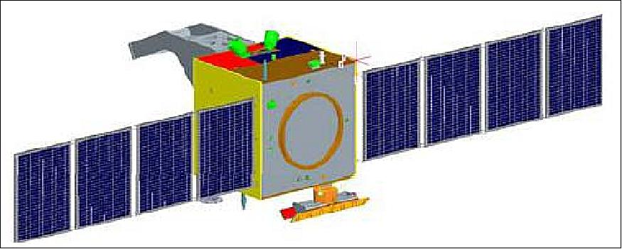
CFOSAT is a spacecraft based on a CNSA funded platform provided by the DFH Satellite Corp., based on its CAST-2000 series satellite bus. The spacecraft has a launch mass of ~ 650 kg, the primary structure has a size of ~1.4 m x 1.4 m x 1.2 m, the mission design life is 3 years. 9)
AOCS (Attitude and Orbit Control Subsystem): The spacecraft is three-axis stabilized.
• Three-axis pointing precision: 0.1º (3σ)
• Three-axis stabilization: 0.01º/s (3σ)
• Three-axis measurement precision: 0.03º (3σ).
EPS (Electrical Power Subsystem):
• Power generation: 1.5 kW (BOL), 1.3 kW (EOL)
• Battery capacity: More than 60 Ah.
RF communications: The TT&C communications are provided in S-band with an uplink rate of 2 kbit/s and a downlink data rate of 16.384 kbit/s. The payload data are provided in a separate downlink (more information is not available).
Launch
The CFOSAT spacecraft was launched on 29 October 2018 (00:43 UTC) on a Long March 2C vehicle of China from JSLC (Jiuquan Satellite Launch Center). CFOSat's solar array deployed successfully 32 minutes later and the satellite started its science mission to study ocean surface winds and waves. 11) 12)
After the announcement of the launch's success, CNES President Jean-Yves Le Gall commented from the Jiuquan launch base: "In 1997, CNES and CNSA signed the first cooperation agreement between France and the People's Republic of China on the study and peaceful uses of outer space. It was in 2014 that we decided to go ahead with the CFOSat ocean-surveying mission, a major project confirming our nations' commitment to tackling climate change and the culmination of a unique partnership in this domain. CNES and CNSA have constantly combined their efforts in this area ever since. We signed a memorandum of understanding in January this year, in the presence of Presidents Emmanuel Macron and Xi Jinping, to step up this cooperation and encourage wide uptake of CFOSat data. These data will be instrumental in the success of the Space Climate Observatory (SCO), one of the flagship measures in the Paris Declaration adopted by the world's space agencies at the One Planet Summit in December 2017."
Secondary payloads (CubeSats)13)
• Xiaoxiang-1, a technology verification test for LaserFleet, a Chinese company aiming to establish a low Earth orbit constellation of 288 laser communications satellites providing broadband access to flights and has signed a cooperation deal with the Civil Aviation Management Institute of China (CAMIC).
• Tianfuguoxing-1 (Xinghe) is a remote sensing and 'AI' demonstration CubeSat in cooperation with Guoxing Yuhang Co. Ltd., or ADA Space, a private firm based in Chengdu which had two payloads on the iSpace suborbital flight in September.
• Zhaojin-1, also known as Tongchuan-1 after a city in Shanxi Province through sponsorship, is also the first of the Gamma Ray Integrated Detectors (GRID), a planned Tsinghua University astrophysics constellation of 24 CubeSats. The satellites will pick up signals from extremely energetic events known as gamma-ray bursts, with the main science goal of identifying and locating the electromagnetic counterparts to gravitational waves such as those famously detected by LIGO. - The 6U CubeSat will also be involved in space-to-ground tests with the newTongchuan commercial space ground station.
• Changshagaoxin, named for the Changsha city High-Tech zone and marks its 30th anniversary, will be an amateur radio payload satellite and also a technology verification for a next-generation 20U Spacety satellite platform.
Orbit: Sun-synchronous near- circular orbit, altitude of 519 km, inclination = 97º, LTDN (Local Time on Descending Node) = 7:00 hours, the revisit time is 13 days (Figure 4).
The CFOSat system will have the capability to achieve a near-real time transmission (i.e. less than 3 hours after the acquisition) of the data to the main centers which run operational atmospheric or wave prediction models, so that the data can be used in assimilation processes and forecast procedures.
With their respective geometry SWIM and SCAT will provide a global coverage within 3 days for wind fields (SCAT) and almost global for waves within 13 days (SWIM).
Mission Status
• June 18, 2019: The Chinese-French Oceanography Satellite (CFOSAT) was launched on 29 October last year, for the China National Space Administration (CNSA) and the Center National d'Etudes Spatiales (the French Space Agency, CNES). 14)
- Under an agreement signed today, EUMETSAT will distribute data from the satellite's payload to its 30 Member States and the European Center for Medium-Range Weather Forecasts in near-real time and perform additional processing of the data.
- "This trilateral cooperation agreement shows how nations and agencies working together can bring benefits for the citizens of Europe in the areas of weather forecasting and climate monitoring," EUMETSAT Head of Strategy, Communication and International Relations Paul Counet said.
- "The national meteorological and hydrological services in EUMETSAT's 30 Member States expressed an interest in receiving the data from CFOSAT's payload, which will help improve the accuracy of weather forecasts and aid understanding of climate change. The CFOSAT mission data, which is expected to be operationally available in autumn, will allow more accurate forecasting and earlier warnings of severe weather events like storms and cyclones. CFOSAT will also help climatologists learn more about the interactions between air and sea, which are key to understanding the climate."
- CFOSAT carries two radar instruments: SWIM, supplied by CNES, to measure wave properties such as direction, wavelength, etc; and SCAT, an instrument supplied by CNSA to measure ocean-surface wind vectors.
- The cooperation agreement was signed by CNSA Vice Administrator Wu Yanhua, CNES President Jean-Yves Le Gall and EUMETSAT Director-General Alain Ratier during the 53rd International Paris Air Show at Le Bourget today.
• April 11, 2019: According to information from Celine Tison of CNES, the CFOSAT project is currently in the commissioning phase. The satellite and its instruments are all behaving well. The project is investigating and qualifying the products. This is a big challenge as SWIM is a very new instrument. Current plans are to open the data to the scientific community in the next summer/autumn. 15)
Sensor Complement
The objectives of CFOSAT will be implemented by joint measurements of the ocean surface wind vector and seastate parameters from radar payloads. Both OSVW (Ocean Surface Vector Wind) and OSWS (Ocean Surface Wave Spectra) can be measured using active microwave remote sensing technologies (with heritages from previous Chinese and French missions of radar altimeter, scatterometer and SAR missions, and airborne radar measurements).
Oceans cover 70% of the globe surface and play a fundamental role in climate, meteorology, environment, economy. Thus, monitoring, understanding and predicting the ocean surface processes is of major importance and even more critical for maritime countries. Particularly, surface wind and waves are key parameters affecting the marine meteorology, ocean dynamics, marine resources, pollution, economy (navigation, fisheries, oil industry, harbor activities, coastal tourism, etc.), coastal environment (sediment transport, pollution diffusion, etc.). 16)
With respect to existing satellite missions, the originality of CFOSAT is that it will provide co-located wind vector fields and directional spectra of ocean waves for wavelengths larger than about 70 m. It will also provide normalized radar cross-section in multi-incidence and multi-azimuth geometry which can be used on one hand to improve the inversion algorithms for estimating wind speed and significant wave height and on the other hand to characterize the small scale roughness of all types of surfaces. 17)
CFOSAT will contribute to the global wind field observations in complement to existing scatterometer missions (e.g. ASCAT on MetOp, SCAT on HY-2A), to provisioning of wind speed and and significant wave height in complement to other altimeter missions (like Jason or HY-2 series, Sentinel-3), and it will provide new information on wave properties with respect to SAR missions (like Sentinel-1), by giving access to directional spectra of ocean waves not only for the long swells but also for wind waves and mixed sea conditions whatever is the direction of these waves.
SCAT (Scatterometer)
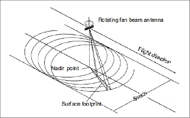
SCAT, provided by CNSA, is a vector wind scatterometer designed and developed at MiRS/CSSAR/CAS (Microwave Remote Sensing Laboratory / Center for Space Science and Applied Research / Chinese Academy of Sciences), Beijing, China. SCAT will be the first RFSCAT (Rotating Fan-beam Scatterometer) pointing at medium incidence angles (26° to 46°) with a dual antenna system; it is flown on a spacecraft for global ocean vector wind observations. 18) 19) 20) 21) 22)
SCAT is a Ku-band RFSCAT with HH and VV polarizations. The expected ocean wind vector retrieval performance is as follows (with 50 km OSVW resolution):
• Wind speed accuracy: 2 m/s or 10% (larger) within the 4~24 m/s wind speed range
• Wind direction accuracy: ±20º within the 360º wind direction range
• Ground geolocation accuracy OSVW resolution cells: < 5 km.
The SCAT hardware system is composed of 14 units. The antenna and part of the servo-mechanism are installed outside the satellite. Other units are installed inside the satellite. Two 1.2 m x 0.4 m wave guide slotted array antenna panels are mounted on the satellite to acquire fanbeam radiation patterns in H and V polarizations. The antenna is rotating while it is connected with the inside units through the axis and RF rotary joint. Part of the servo-mechanism is fixed to the satellite. A TWTA (Travelling Wave Tube Amplifier) provides 120 W pulse modulated output power. The main system parameters of the scatterometer are listed in Table 2.
Center frequency | 13.256 GHz (Ku-band) |
Bandwidth | 0.5 MHz |
Polarizations | HH, VV |
Swath width | > 1000 km |
Surface resolutions | < 50 km |
Radiometric precision | < 1.0 dB (with 4~6 m/s wind speed) |
Antenna beam shape | Fan pencil beam |
Antenna size | ~1.2 m x 0.4 m x 0.4 m |
Antenna gain | 22~30 dB (within the swath) |
Receiver sensitivity | Better than -130 dBm |
System dynamic range | ~45 dB (-30 dB~+15 dB) |
Precision of internal calibration | Better than 0.15 dB |
Rotation speed | < 6 rpm |
Pulse width | 1 ms~4 ms |
Duty cycle | 15%~35% |
PRF (Pulse Repetition Frequency) | 80 Hz < PRF < 200 Hz |
Rotation momentum | < 0.170 Nms (TBC) |
Power consumption | < 200 W |
Instrument mass | < 70 kg |
The design of SCAT is based on simulations of the performance implementation, available technology heritages and the constraints of the platform. The key characteristics of the design are:
SCAT transmits a long LMF pulse and receives its signals with the de-ramp pulse compression, where the Tx pulse length and the Rx receiving window are 1.35 ms and 2.72 ms, respectively, which is a function of the observation geometry and the orbital altitude. To satisfy the downlink data rate limitation of 220 kbit/s, a digital I-Q receiver with an on-board pulse compression processing and resolution cell regrouping will be used, which results in a downlink σο surface resolution of about 10 km (azimuth) x 5 km (elevation).
SCAT features three operational modes:
• Nominal mode: dual polarization with rotation for OSVW measurement
• Test and calibration mode: raw waveform collection with lower PRF, including both rotating mode and fixed pointing mode
• Single polarization mode.
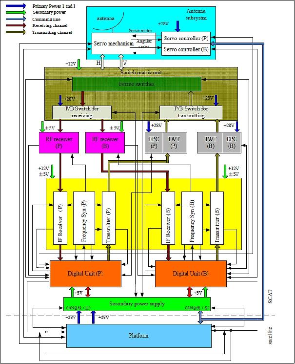
The SCAT instrument features the following functional subsystems:
• Antenna subsystem, including the antenna and feeding network, the scanning mechanism and the servo controller
• RF subsystem, including the RF switch matrix and the RF receiver
• Rx/Tx electronics subsystem, including the IF receiver, the frequency synthesizers and the Tx upconverter
• Power amplifier subsystem, including the TWT (Traveling Wave Tube) and the EPC (Electrical Power Conditioner)
• Digital subsystem, including the signal generator, the system controller, the signal processor and the data communication controller
• Secondary power supply subsystem, including the DC/DC power converter and the TC/TM module
• Waveguide and cable assembly.
To insure the liability and lifetime of the instrument, the Tx/Rx channels, except antenna and switch matrix, will be equipped with an identical primary/backup design.
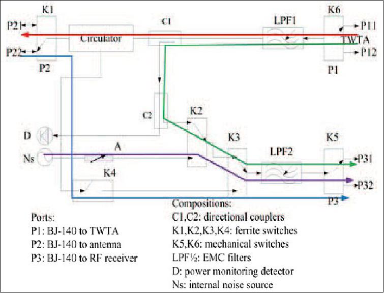
Internal calibration: Internal calibration is used to compensate the fluctuations of transmitted power and T/R channel gains. In addition, by internal calibration, the absolute receiving power measurement can be transformed to the measurement of the receiving voltage ratio between measurement and calibration. Figure 7 illustrates the composition of the internal calibration loop.
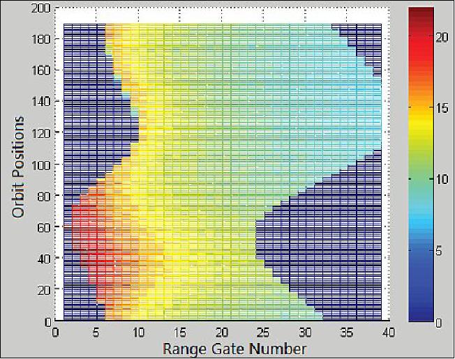
Doppler Compensation: For a spaceborne rotating fanbeam scatterometer, the large swath and footprint result in a wideband Doppler frequency shift. For a low Earth orbiting satellite like CFOSAT, the maxim Doppler bandwidth between forward and backward echoes will be about 500 kHz. Even in a single echo of RFSCAT, the Doppler bandwidth is about 90 kHz, while in a pencil beam scatterometer the Doppler bandwidth is almost a single tone. For a chirp radar, the Doppler Effect will confuse the frequency shift caused by range and relative velocity. So a method of Doppler frequency compensation both on center frequency of transmitted pulses and signal processing section of the echoes are carried out and evaluated. Figure 8 shows the final range gate resolution of a fixed azimuth angle center frequency after center Doppler frequency and residual Doppler compensation.
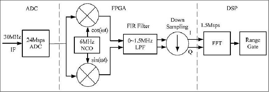
Onboard processing: The onboard signal processing system consists of a digital receiver, FFT (Fast Fourier Transform) and range gate arrangement section. The block diagram of the onboard signal processing progress is shown as Figure 9. The onboard processing functions include:
• Source data rate reduction to ~ 220 kbit/s
• Reduction of the downlink data resolution to about 10 km (az) x 5 km (el) from the original resolution of 10 km (az) x (<1 km (el)
• Provision of the the "signal+noise" processing and the "noise-only" processing to satisfy the radiometric resolution for low wind speed cases.
The main functions of the SCAT onboard signal processing include the pulse compression, power estimation by accumulation, and elevation range bin regrouping.
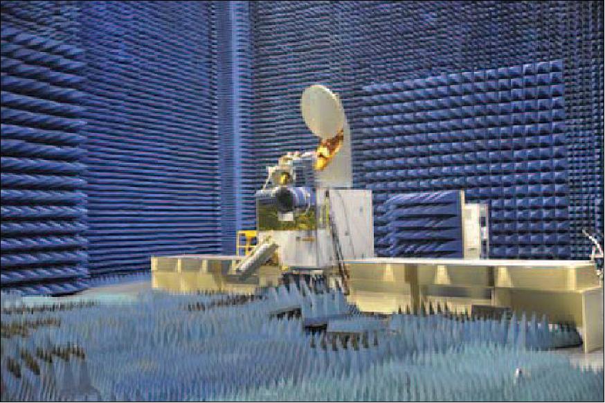
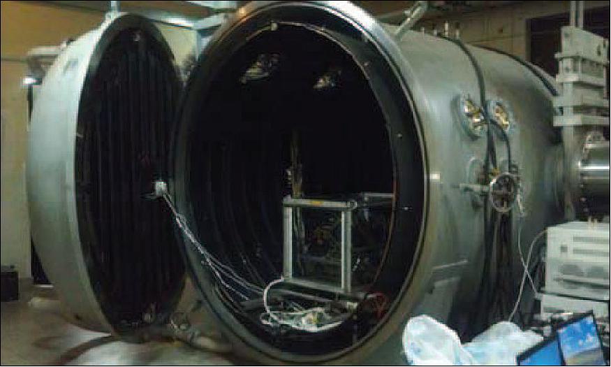
Validation experiment: Considering that SWIM and SCAT both work at Ku-band, an EMC (Electromagnetic Compatibility) test using physical radiated models of SWIM and SCAT is very useful. Figure 10 shows the CFOSAT EMC test in a chamber.
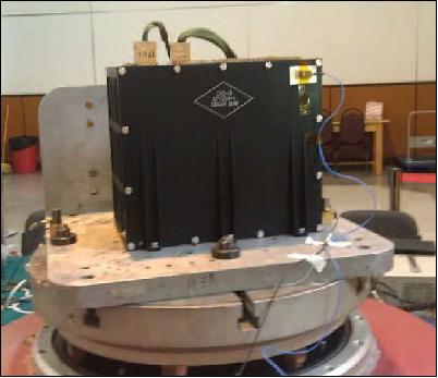
The mechanical qualification tests are carried out to qualify the design of the SCAT instruments structure and performance of instrument. All the SCAT instruments have withstood the qualification test, including sinusoidal vibrations, random vibrations and shock loads. In the thermal environment test, thermal vacuum test and thermal cycle test. Figure 11 and Figure 8 show the pictures of instruments in mechanical test and thermal vacuum test.
Simulation of RFSCAT
The CFOSAT RFSCAT instrument uses two parallel, rotating slotted-waveguide array antennas with two fan beams corresponding to vertical and horizontal polarization that scans in a conical pattern. The RFSCAT produces large overlaps on the observation regions within the total swath by successive sweeps and provides a large number of σο acquisitions with diverse azimuth and elevation combinations for a single surface resolution cell. It is expected to acquire frequent global coverage and high quality wind acquisitions. 23)
Unlike SeaWinds and ASCAT scatterometers, the Doppler effects of RFSCAT introduced by the relative motion between the scatterometer and Earth's surface with its rotation are 3-D coupling distributions varying with the latitude position of the satellite, as well as the azimuth and elevation of the resolution cells. A frequency pre-shift LUT (Look-Up Table) for transmitting signal by shifting central frequency of transmitting signal is used, and the residual Doppler frequency shift compensation and slice division processing onboard are combined into one step via a well-designed azimuth related 1D LUT to implement.
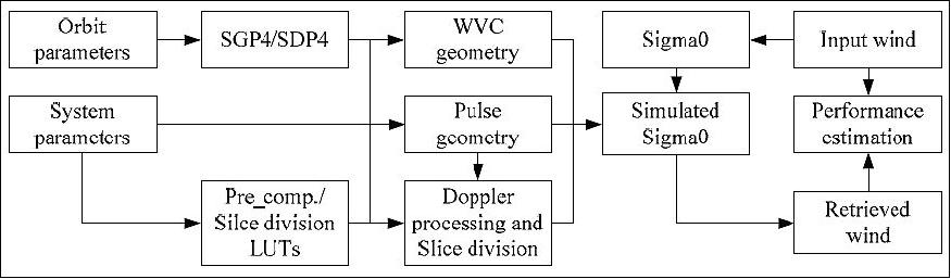
A data simulation system of CFOSAT RFSCAT is developed for signal processing algorithm validation and performance analysis. An end-to-end simulation model, which is considered for the actual CFOSAT RFSCAT onboard processing such as Doppler frequency shift compensation and slice division, is adopted. Meanwhile, the NORAD SGP4/SDP4 (Simplified General Perturbations Satellite Orbit Model 4) orbit propagation model is used for pulse and WVC (Wind Vector Cell) observation geometry computation. The input data set could be simulated random wind field or ECMWF NWP wind field. Under the simulation system, The SNR and the communication error of slices and WVCs for different azimuth scan direction are provided and analyzed. Taking the pseudo-L1B data which including the WVC geometry, Kpc coefficients and SNR related information of observation views and the ECMWF wind data, the sigma0s (σο) are simulated and the winds are retrieved and the wind retrieval performances such as the wind speed bias and wind direction rms error are estimated. On the other hand, some considerations of the actual ground data processing are introduced.
Figure 13 is the diagram of end-to-end CFOSAT RFSCAT simulation system. With the orbit parameters and scatterometer system parameters, the pulse geometry, WVC geometry and the slice geometry are obtained based on the SGP4/SDP4 orbit propagation model. Especially, the Doppler frequency pre-shift LUT and slice division LUT should be calculated in advance and taken as reference for onboard signal processing and simulation. The WVC geometry, the communication error and SNR related information are used for the generation of simulated sigma0, together with the input wind field. After wind retrieval processing on the simulated sigma0, the wind retrieval performance of CFOSAT RFSCAT could be estimated and analyzed.
SWIM (Surface Waves Investigation and Monitoring Instrument)
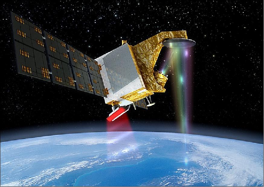
SWIM is a new CNES Ku-band radar instrument, manufactured by TAS (Thales Alenia Space), Toulouse, France; it is based on the technology of a spaceborne radar altimeter. SWIM is the first ever space radar concept that is mainly dedicated to the measurement of ocean waves directional spectra and surface wind velocities through multi-azimuth and multi-incidence observations. Orbiting on a 519 km sun-synchronous orbit, its multiple Ku-band (13.575 GHz) beams illuminating from nadir to 10º incidence and scanning the whole azimuth angles (0-360º) provide with a 180 km wide swath and a quasi global coverage of the planet between the latitudes of ±80º. 24) 25) 26) 27) 28) 29) 30) 31) 32)
Scientific requirements for wave measurements: The main objective of SWIM is to provide directional wave spectra. The products delivered to users shall reach the following accuracies: 33) 34)
• Nadir measurements:
- Accuracy on SWH (Significant Wave Height) better than 10% or 50 cm (maximum)
- Accuracy on wind speed about ± 2 m/s or 10% (whichever is the larger).
• Wave spectrum measurements (beams 6°, 8°, 10°):
- Resolution cell of 70 x 90 km2 for wave spectra
- Observable wavelengths of waves in (70 m, 500 m) with an accuracy from 10% to 20%
- Azimuth resolution in wave propagation direction : 15°
- Accuracy in wave spectrum level : 15% within the half wave energy bandwidth with respect to the peak.
• Backscattering coefficient measurements:
- Absolute accuracy of ±1dB, relative accuracy between beams ±0.1dB.
Such a wide range of observations, requiring high-range resolution (about 20 m on the ground), have led to design an instrument whose architecture and technology goes beyond what has been done on altimeter and scatterometer implementations. The global coverage and the reduction of telemetry budgets have required performing onboard range compression. The variety of signals at different incidences, the impact of the complex moving geometry of observation and the required real-time signal processing have led to propose onboard complete digital range compression on backscattered 320 MHz bandwidth signals. The design of the onboard compression and processing resulted from a trade-off between the instrument high level performances required, the needed correction for geometrical effects such as range migrations and performance of the acquisition and tracking loops.
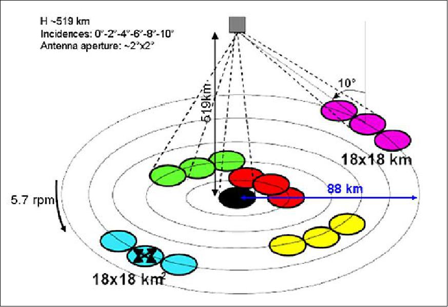
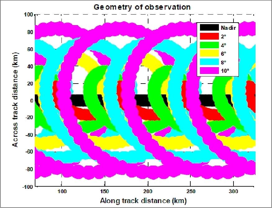
The multi-azimuth multi-incidence observations requirements have led to design an ambitious antenna subsystem that rotates at 5.6 rpm while transmitting six high power RF signals towards tunable directions. This configuration (Figure 14) allows a 180 km wide swath and a quasi global coverage of the planet between the latitudes of ±80º.
• Real aperture radar SWIM instrument
- Ku-band (320 MHz bandwidth)
- On-board digital processing
- 6 distinct beams between nadir and 10° incidence (0°, 2°, 4°, 6°, 8° and 10°)
- Rotating antenna at 5.6 complete rotations/min.
The six beams enable to measure several geophysical parameters:
• with all beams: estimation of backscattering coefficient profiles from 0° to 10° of each surface
• with nadir beam (0°): estimation of SWH and wind sea surface, similarly as nadir altimeter
• with 6°, 8° and 10° beams (named "spectrum" beams): estimation of the 2D wave spectra.
Main parameters of SWIM: Table 3 summarizes the main characteristics of the instrument. Table 4provides the parameters of the six incidence beams of SWIM. Note that some parameters (integration time and PRF) have been recently changed with respect to what was presented in previous publications, in order to guarantee compatibility with electrical constraints of the platform.
The cycle is the consecutive time spent at a given incidence and the macro-cycle is the elementary set of cycles, which combines all incidences. The nominal macro-cycle is (0°, 2°, 4°, 6°, 8°, 10°) but it can be remotely modified during flight. Note that the PRF is adaptive along the orbit whereas the number of averaged pulses per cycle is kept constant (Table 4).
Frequency | 13.575 GHz |
Useful bandwidth | 320 MHz |
Useful pulse duration | 50 µs |
Peak power | 120 W |
Incidence angles (on ground) | 0º, 2.43º, 4º, 6º, 8º, 10º |
PRF (Pulse Repetition Frequency) | from 5 to 5.4 kHz |
Antenna rotation speed | 5.6 rpm |
Antenna diameter | 90 cm |
Antenna 3 dB aperture | >1.5º (0º and 2º); >1.7º (from 4º to 10º) |
Polarization | Linear (VV in rotation) |
Parameter / Incidence | 0º | 2º | 4º | 6º | 8º | 10º |
NIMP | 264 | 97 | 97 | 156 | 186 | 204 |
RA (Rank of Ambiguity) | 18 | 18 | 18 | 18 | 18 | 18 |
PRFmin | 5093 Hz | 5079 Hz | 5079 Hz | 5065 Hz | 5037 Hz | 5023 Hz |
PRFmax | 5427 Hz | 5427 Hz | 5411 Hz | 5305 Hz | 5379 Hz | 5348 Hz |
T cycle min | 52.0 ms | 21.3 ms | 21.3 ms | 32.3 ms | 37.9 ms | 41.5 ms |
T cycle max | 55.4 ms | 22.6 ms | 22.6 ms | 34.4 ms | 40.4 ms | 44.2 ms |
T cycle max (hors RA x PRI) | 51.8 ms | 19.0 ms | 19.1 ms | 30.8 ms | 36.8 ms | 40.6 ms |
Legend to Table 4: NIMP = Number of useful transmitted pulses per cycle (see Figure 22).
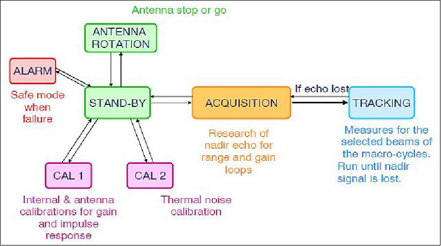
Main modes: The main operating modes of the instrument are (Figure 15):
• STAND-BY when SWIM is ready and waits for the transition to one of the measurement modes
• ACQUISITION when SWIM computes the acquisition time windows from the detection of the nadir echo (temporary mode before switching to tracking)
• TRACKING when SWIM measures the backscattered power of the echo for successive cycles and macro-cycles; this is the scientific mode
• CAL1 when SWIM performs internal calibration (including rotary part of the antenna calibration)
• CAL2 when SWIM measures thermal noise. It is also possible to operate SWIM with different macro-cycles, with a fixed antenna (no rotation).
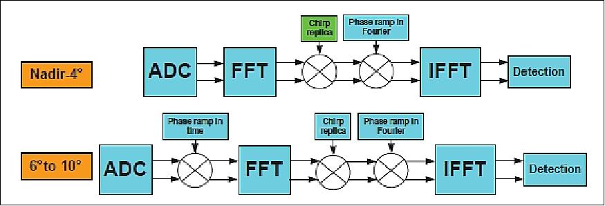
On-board processing: On-board processing is performed to reduce the data rate: the chirp scaling, the power detection, the swath selection as well as time and range summations are computed. The chirp scaling includes range compression and compensation of range migrations before summation. This migration compensation and the number of integrated samples (or time duration) have been defined by taking into account a trade-off between the need for data and speckle reduction, and the need for keeping a ground horizontal resolution of at least 35 m.
Finally, the downloaded signal for each cycle consists in the mean backscatter power versus range provided with a range resolution and number of points in the swath as given in Table 5.
Parameter / Incidence | 0º | 2º | 4º | 6º | 8º | 10º |
Resolution (m) | 0.47 | 1.88 | 1.88 | 0.94 | 1.41 | 1.41 |
Number of points | 256 | 754 | 933 | 2772 | 2638 | 3216 |
The ground projection of several (6) nominal macro cycles of the SWIM instrument is illustrated in Figure 16.
The RF (Radio Frequency) radiating performances have to be warranted for each of the 6 beams on the 360º rotation under flight conditions. In particular, the antenna subsystem shall ensure the pointing stability of each beam under rotation throughout the 3 years of nominal mission life. The antenna design shall also minimize the impact of mechanical and thermal environments on its critical components (active equipments).
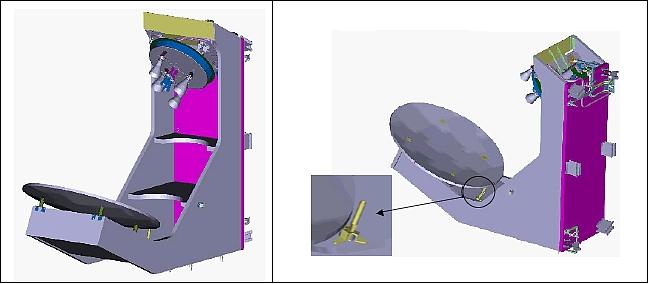
SWIM Antenna Assembly
The antenna design, operating in transmit and receive modes, features an offset reflector geometry combined with the RFA (Rotating Feed Assembly), including 6 horns and a switch matrix, allowing to switch the RF signal between each horn. The RF rotary joint, which is part of the complex RMA (Rotary Mechanism Assembly), ensures the interface between the fixed RF part and the rotating one. A stepper motor allows the precise rotation of the RFA. The rotating RFA is electrically fed and controlled using a collector, the RMA is aligned by a set of bearings.
A calibration probe is implemented close to the reflector to be able to calibrate each of the 6 beams in flight conditions (Figure 17). The SWIM antenna is electrically fed and commanded by a dedicated APCE (Antenna Power and Command Equipment).
The multibeam SWIM antenna is comprised of the following elements:
• A composite mechanical structure supporting the reflector and the rotating feed
• A rotating feed including:
- RMA (Rotary Mechanism Assembly) composed of a RF rotary joint, a motor, a collector, two bearings, and a HARM (Hold And Release Mechanism) system
- RFA (Rotary Feed Assembly) including a switch matrix in ferrite technology with associated drivers and 6 horns with associated mechanical plate
• A passive calibration system allowing to calibrate in flight conditions the 6 antenna beams
• An antenna thermal control device.
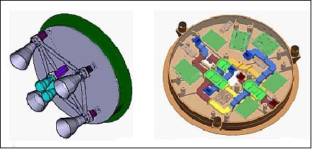
RFA (Rotary Feed Assembly): The RFA is composed of 6 horns, a switch matrix and a mechanical interface structure. The RFA is rotating at 6 rpm (revolutions per minute) in the instrument nominal operating mode. To obtain the optimal performance for each beam, three different designs have been optimized for the horns. The location of the horns on the rotating plate has been optimized to comply with the beam pointing requirement as well as the center of gravity, inertia, and the interfaces with the switch matrix.
The switch matrix allows to switch the RF signal between the 6 beams - which operate in transmit and receive modes. The matrix includes 5 ferrite switches with electronic driver devices. The ferrite switches are RF interconnected by WR62 waveguide junctions. The switch locations and the routing of the waveguide junctions have been enhanced to minimize the RF losses and to be compliant with the rotating plate mechanical interfaces.
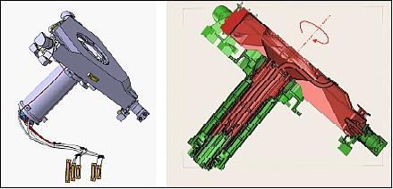
RMA (Rotary Mechanism Assembly). The RMA is developed in the frame of the CNES/TAS SWIM instrument. It is a high lifetime mechanism enabling the holding, the release and the rotation of 6 RF beams integrated on an antenna structure at 5,6 rpm continuously during 3 years (qualification needs: 13,6 millions of turns). This mechanism is composed of a rotary for the rotation (with a RF joint and a slip-ring for digital commands in particular), and by 3 HRMs for the holding and the release. 35)
The RMA supports the following functions:
• Stowage of the RFA during the launch sequence
• Rotate the RFA with accuracy and stability
• Provide the RFA angular positioning
• Transfer the feed and command signals from the APCE to the switch matrix
• Transfer the RF signal between instrument RF unit and RFA
• Transfer the electrical grounding to RFA.
The RMA is composed of the following elements:
• A stepper motor
• A collector for electrical signal transmission
• The RF rotary joint
• Two bearings
• A set of 3 HARMs (Hold and Release Mechanisms)
• A set of mechanical interfaces.
Mechanical and thermal design of RFA and RMA: The mechanical and thermal designs have been optimized to limit the constraints on the RFA and RMA devices.
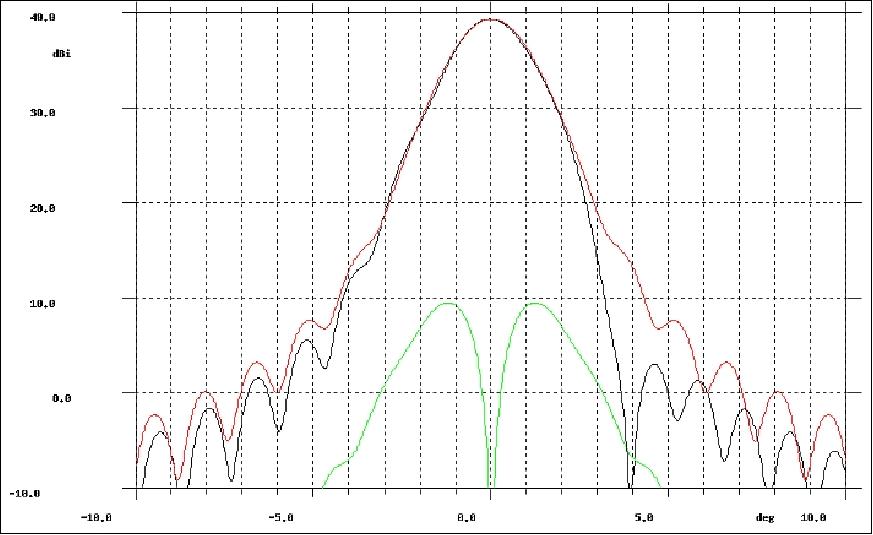
SWIM antenna RF performance: One of the most critical RF performance parameters to optimize was the beam aperture evolution minimization (aperture evolution lower than 10%) as presented in Figure 20 for the 10º beam example. For this particular beam, strongly depointed from nadir, the unsymmetrical side lobe effects have been minimized (Figure 21).
The worst case RF performance analysis has met compliance with the RF antenna requirements.
SWIM Instrument Description and Operations
SWIM is a RAR (Real Aperture Radar) to provide 1D range sampled echoes, from which an adequate processing leads to the retrieval of radar cross-section profiles with respect to incidence and wave spectrum characteristics. Observations in 2D require a rotating system in order to cover the azimuth direction. Useful profiles require to span the beam incidences up to 10º.
The instrument consists in a rotating antenna intended to transmit signal towards six distinct directions. The antenna consists of a rotary feed placed in front of a reflector in an offset configuration. This rotary feed is composed of 6 horns mounted on a circular plate rotating at ~6 rpm order to reach the six distinct directions. Such a configuration provides with a filled 180 km swath at an altitude of 519 km.
The functioning of the instrument relies on the definition of six distinct periods of time, called cycles, each related to one given beam. A cycle is constituted of three distinct subcycles, a first one where pulses are only transmitted but no backscattered echoes are received yet, a second one where transmitted and received signals alternate and finally a third one where the last transmitted signals are received. The architecture of a cycle is illustrated in Figure 22 (Ref. 29).
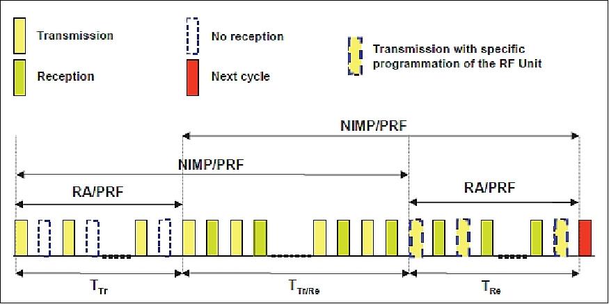
Legend to Figure 22:
- RA = Rank of Ambiguity
- NIMP = Number of useful transmitted pulses per cycle
- PRF = Pulse Repetition Frequency.
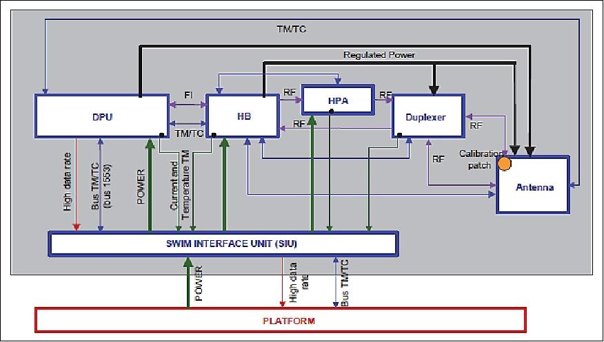
The SWIM functional block diagram is shown in Figure 23. The instrument is comprised of 6 distinct units. The SIU (SWIM Interface Unit) communicates on the one hand with the platform (power and TM/TC), and on the other hand with the heart of the radar, providing with power to the DPU (Digital Processing Unit), HB (Hyperfrequency Box) and HPA (High Power Amplifier); it is also taking care of the TM/TC dialog with the DPU.
HB (Hyperfrequency Box): HB gathers all the analog functions of a radar (bandwidth expansion, frequency translations, local oscillator generation, low noise amplification, base band conversion, bandwidth filtering). It is a new design compared to the current nadir altimeters architecture. Indeed, it considers an integrated architecture:
- at the transmission level, the direct translation from an analog baseband signal with 160 MHz bandwidth on I & Q to a 320 MHz bandwidth RF signal carried at 13,575 GHz using a direct modulator
- at the reception level, the direct demodulation of the received 320 MHz bandwidth signal in Ku band to base band using a direct demodulator.
It leads to a symmetric frequency plan between transmission and reception paths and a significant decrease in mass and power budgets.
DPU (Digital Processing Unit): The DPU gathers all the digital (hardware and software) processing of the whole instrument (digital chirp generator, digital compression, range migration correction, radar echoes processing, instrument interface with the platform computer). The swath durations increase significantly when going at high incidences, then providing with a large amount of samples that have to be processed onboard with large FFT's. Figure 24 illustrates the digital compression stage. Processing has to be performed at high rate (up to 7 kHz) on 32768 complex samples. It requires the use of two ASICs.
The data from obtained observations will provide the SWH (Significant Wave Height) for the off-nadir beams (i.e., 6-10º), and the ocean wave directional spectra; the nadir beam will provide the SWH and the surface wind speed, similarly to altimeter missions. The wave spectra will be analyzed in terms of the wavelength, direction and energy of different partitions of the wave spectra. In addition, the backscattering coefficient profiles will be provided with a continuous sampling from 0º to 10º.
Summary of CFOSAT mission capabilities (Ref. 16):
• CFOSAT is a world premiere mission : simultaneous measurements of wind (SCAT) and directional spectra of ocean waves (SWIM)
• Access for the first time in space to 2D wave spectrum over the whole energetic spectrum (~70-500 m) at global scale, potential for complex sea situations (multi-wave systems)
• SCAT: implementation of a new type of Scat (Rotating Fan-Beam)
• SWIM is a new spaceborne instrument with technological innovations
- Rotating antenna, on-board advanced digital processing
• CFOSAT, as a new component contributing to spatial oceanography systems, will:
- Serve the operational community (wind/wave forecast, ocean surface analysis for ocean model forcing)
- Serve the scientific meteo-oceanographic community (new data for studying wind/wave/flux/boundary layers interactions)
- Reinforce international multi-mission observation strategy for a better survey of the ocean surface.
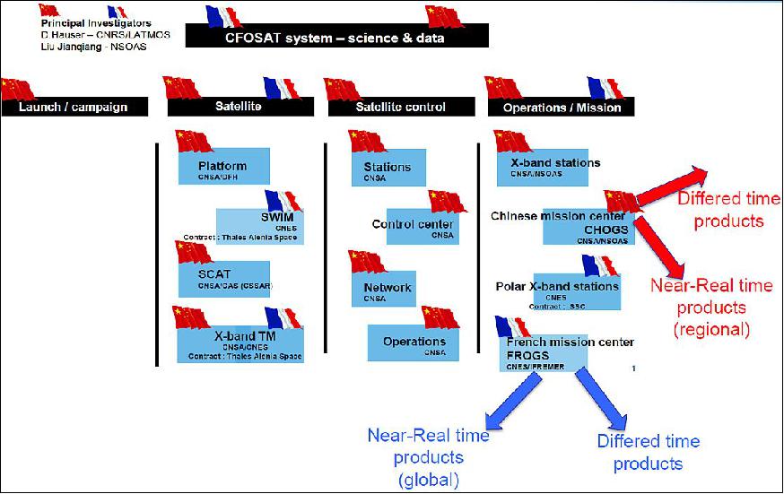
Ground Segment
The ground segment is composed of:
• One Mission Center in Beijing
• One Control Center in Xi'an
• An Instrument Mission Center in Toulouse
• A Waves & Wind Mission Center in Brest
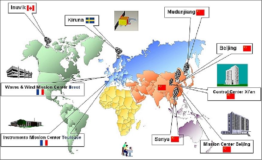
• Ground stations at various locations. CNES will provide a polar station network based on two Earth stations located in Inuvik (Canada) and Kiruna (Sweden). The system has therefore the capability to download the science data on every orbit.
The CFOSAT French Ground Segment : The Global Architecture
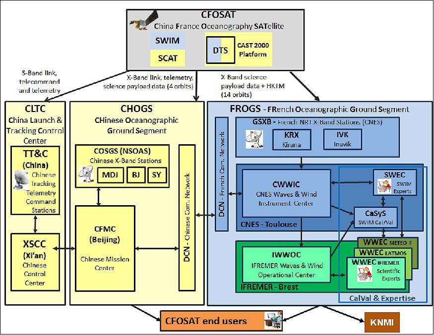
In Figure 26 are represented all the components of the CFOSAT ground segment with the Chinese mission control center (CLTC), the CHinese Oceanographic Ground Segment (CHOGS) and finally the FROGS (FRench Oceanographic Ground Segment). 36)
First, the GSXB (Ground Segment X-band) is the component that acquires the telemetry data with the X-band from both Inuvik and Kiruna ground stations. The CWWIC (CNES Wind and Wave Instrument Center) is the CNES realtime operational center where NRT (Near Realtime) products are generated as well as where the mission is planned (SWIM telecommand). The IWWOC (Ifremer Wind and Wave Operational Center) is the IFREMER differed time mission center where L3 and L4 data are generated and distributed. The SWEC (Swim Wave Expertise Cell) is the CNES expertise cell where NRT and all products are analyzed at a first glance. It is also the SWEC, that monitors the overall behavior of the SWIM instrument. The WWECs (Wind and Wave Expertise Centers) are the expertise centers that are in charge of the scientific analyses of the data and products. These WWECs are identified as Météo-France, the IFREMER and the LATMOS. The goals of the WWECs are to make sure of the quality of the products and submit new algorithms to the scientific CFOSat community in order to improve the NRT SWIM chain. Finally, the DCN is the component that exchange the data between the Chinese and French mission centers.
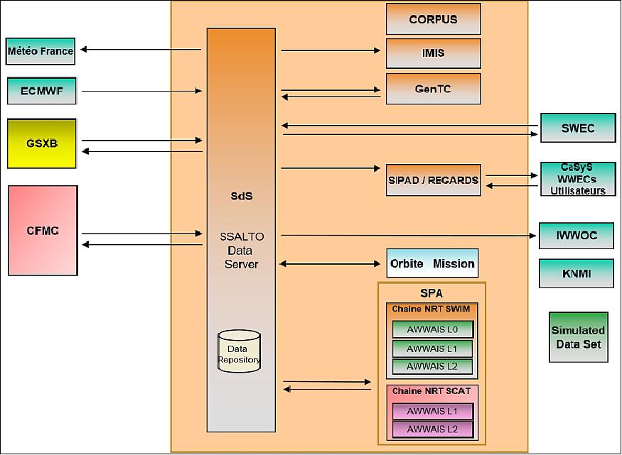
The heart of the FROGS (FRench Oceanographic Ground Segment) is the CWWIC. The CWWIC is strongly based on SSALTO (Segment Sol Altimetrie et Orbitographie), a multi-mission altimetry center for (Jason-2 and Jason-3, Saral-Altika, ...) that has generic components or ‘bricks'. The objectives behind using generic components is to better adapt to the future missions with faster and cheaper evolutions of these components. The re-use of these components are shown in Figure 27 (filled in orange) which is a global view of the CWWIC architecture. The SPA component with the AWWAIS brick is fundamental to the CWWIC as the SPA orchestrates the CFOSAT algorithms/executables : the AWWAIS for the SWIM instrument and the SCAT instrument. The SdS brick ensures file transfer between components and external interfaces if needed. The IMIS component is the first level of instrument monitoring. It ensures that if some instrument measures diverge too much (e.g. temperature) or if some extrema are reached on some of the instrument fields, some flags are rised and the exploitation is correctly warned.
The GenTC component is the telecommand generator with payload TC plan generation capability as well. The SIPAD is the archiving component, where the hot and cold data is being stored for the external interfaces such as the CaSys (scientific group that is in charge of the systematic CAL/VAL), the expertise centers and the final users. The SIPAD will soon be replaced by REGARDS, a new component, based on micro-services, which will allow for optimized storage of all the CFOSAT products. The CORPUS component facilitates the reprocessing aspects. It allows to reprocess all products in a short time frame with high performances: for the CFOSAT mission, one year of products need to be reprocessed in one month which is twelve times faster than the operational processing. The external interfaces identified are: Meteo-France, the French Operational Meteorological Agency, which will be the end-user for the NRT product, ECMWF (European Centre for Medium-Range Weather Forecasts) which provides the meteorological input data for the mission, the X-band ground segment component, the Chinese mission center, the IWWOC which needs our data to generate the L3 and L4 product in differed time, and finally the SWEC, the CNES internal expertise cell, which has a global view on all products.
SWIM Products: Definitions and Performances
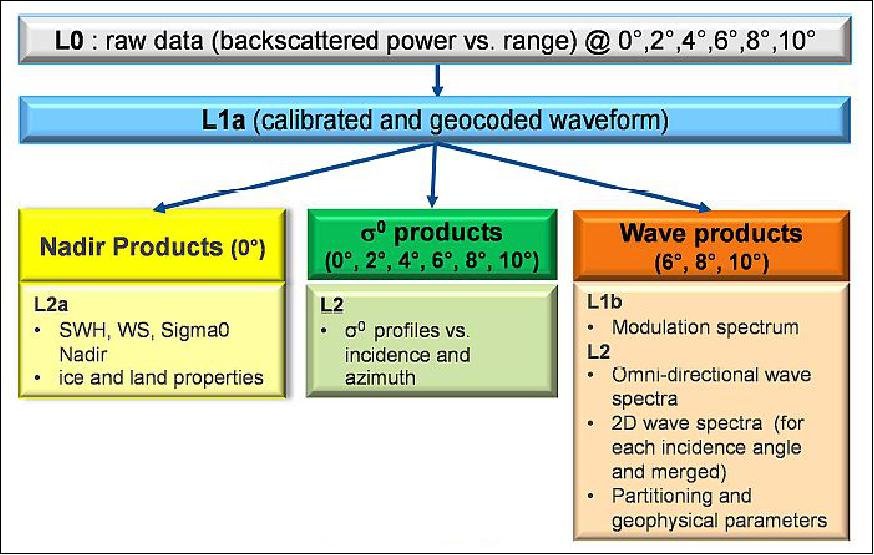
The SWIM products contain three main kinds of variables (Figure28): backscattering profiles from the six beams, wave spectra from the 6°, 8° and 10° beams and SWH and wind speed from the nadir beam.
In order to prototype the ground segment algorithms, simulations have been performed with an end-to-end simulator. Hindcasted wave fields of the wave model (MF-WAM) of Meteo-France are used as input of the simulation to get sea surfaces along the orbit. The simulations in terms of radar signal (accounting for geometry, radiometry and noise effects) are then performed with these synthetic sea surfaces, which vary along the orbit. Finally inversion is performed using the principle implemented in software prototypes of the ground segment. 37)
The Level 2 output consists in 2D wave spectra in cells of 70 km x 90 km on each side of the satellite track, as well as wave parameters (significant wave height, peak direction, peak wavenumber) corresponding to up to 3 partitions of the full wave spectra. The partitioning method is a watershed method that we have adapted from to the case of noisy data. 38)
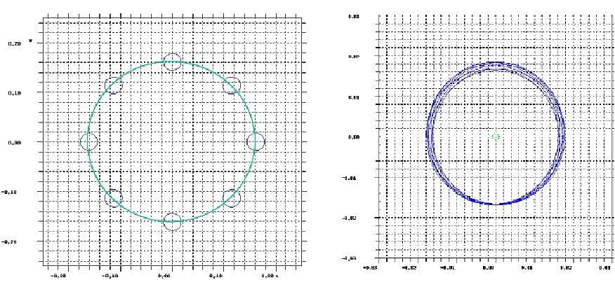
For the performance study, these retrieved parameters are compared to the reference parameters given from the wave spectra used as input. An example of a retrieved 2D wave slope spectrum is given in Figure 29 (Left). This case corresponds to a mixed sea case with a swell and a wind-sea component, both in the same direction. In Figure 29 (Right), the comparison between the input height spectrum and the retrieved spectrum is shown. Qualitatively the agreement is good, however, with an overestimation of the wave height energy density close to the peak of the spectrum. Systematic comparisons have been done on a full orbit of synthetic data generated along the CFOSAT orbit. Furthermore different methods for correcting speckle noise have been implemented and tested.
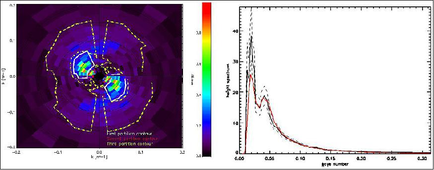
Legend to Figure 29: Left: Wave slope 2D spectrum. Energy in color level, wave number as distance from the center, wave propagation direction as angle from the North with a 180° ambiguity. The 3 detected partitions are indicated as solid white, dashed red and dashed yellow lines. Right: 1D wave height spectrum corresponding to the example of Figure 29 Left, a (black solid line). The confidence interval is indicated as dashed lines. The red curve is the reference spectrum used as input of the simulation.
Figure 30 presents the performance in terms of mean relative bias of the estimated geophysical parameters for one of these methods (assuming a speckle model as proposed by Hanson). 39) For statistics combining all partitions, the bias on wave number and peak direction is compliant with performance specifications in all sea state conditions. The mean bias on energy is also compliant with specification, but only for partitions with wave heights larger than 2 m. The degradation in performance at small wave heights seems to be due to underestimation of speckle level. Work is under progress to select the most appropriate method for speckle correction, and to correct for remaining bias using significant wave height measured at nadir (altimeter mode).
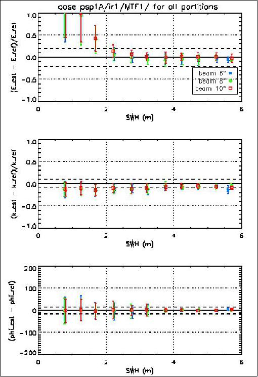
Table 6 provides the bias and scatter index of the inverted parameters for all partitions with wave heights larger than 2 m. Results are within the expected performance range, except for the standard deviation in direction which is higher than expected. Work is under progress to improve the partitioning method in order to better retrieve the wave direction.
Parameter |
| 6º | 8º | 10º |
Energy | Relative bias | 0.4% | 0.6% | 0.6% |
Scatter index | 13% | 13% | 12% | |
Wave number | Relative bias | -10% | -10% | -9% |
Scatter index | 13% | 13% | 13% | |
Direction (º) | Absolute bias | -1.9º | -0.3º | -1.1º |
Standard deviation | 28º | 26.5º | 27º |
In summery, SWIM is a very innovative and promising instrument to provide directional spectra of ocean waves, in combination with surface winds measured by the SCAT. Simulations performed for evaluating the performance on the geophysical products are going on and will help to select the best retrieval algorithms in particular for speckle corrections and to define validation/calibration procedures. The application field sounds promising both for operational and research purposes. The on-board flight model is currently under manufacturing for a launch planned mid of 2018.
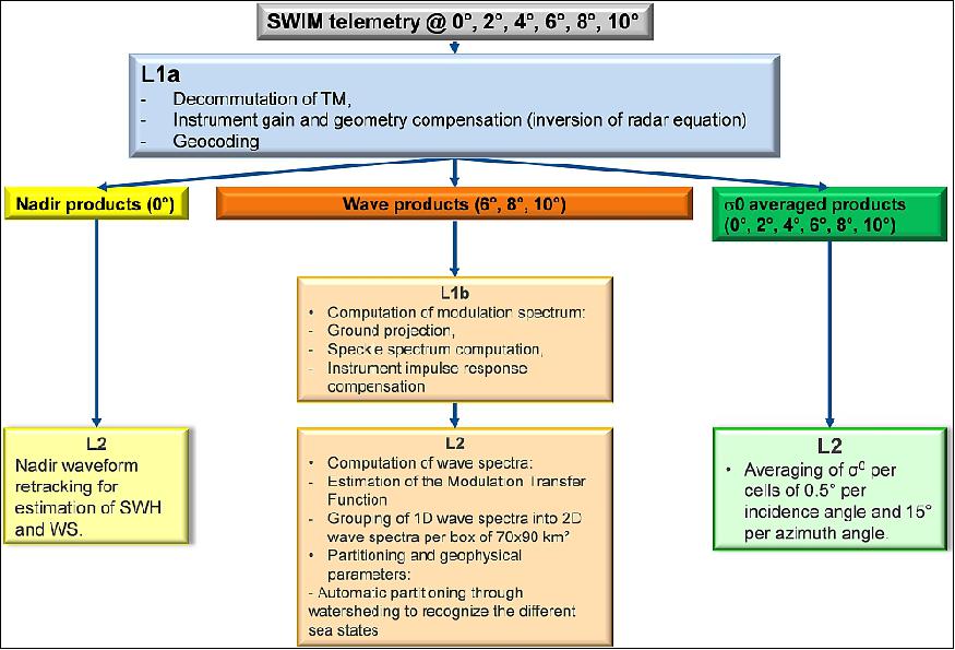
The SWIM products will be operationally generated and distributed by the CWWIC in near real time (i.e. less than 3 hours from the measure to product distribution). The operational processing chain generates three types of products: the nadir products, the σ0 products and finally the wave products. All products are described in Figure 31. Although CFOSat is not a traditional nadir mission, the nadir products are the nadir waveform retracking and give a good estimation of both the Significant Wave Height (SWH) and the Wind Speed (WS) which is a primary objective of the mission. The wave products are only generated with the spectrum beams (6°, 8° and 10° beams) and give an estimation of the 2D wave spectra analysed at the scale of the rotating footprint from fluctuations at the radar signal due to the tilting of long wave. The sigma 0 products are the averaged profile of the retrodiffusion signal on 0.5° cells per incidence angles and 15° angle. The L1a is common to all three types of products as it first decommutes the telemetry and second it will geocode and calibrate the waveforms for all incidences. CNES and LATMOS both developed prototypes softwares that allow for representative dataset (i.e. simulated dataset) for all data levels. The representativity of the dataset is both functional and scientific. Indeed, the simulated data have the same interfaces and format as the operation processing chain and they are at the origin of all the algorithms specifications (Ref. 36).
SWIM Algorithms Development and Validation
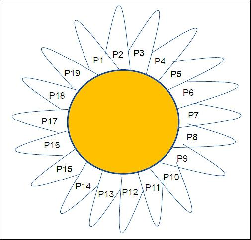
In April 2016, Capgemini has begun to develop the operational processing chain, except the nadir processor which is CLS responsibility, and has thus the responsibility of the overall assembly, integration and validation of the processing chain. In order to take into account the fast evolving algorithms specifications, they used the ‘Daisy' method which is a mixed between the classic V-cycle and the agile method. Basically, there is a common flower head (the yellow circle in Figure 32) which represents the development and validation of what is common to all processors (cots, generation procedures, installation procedures, error management, etc.). The petals (P# in Figure 32)
References
1) http://smsc.cnes.fr/CFOSAT/index.htm
2) Danièle Hauser,Jianqiang Liu, "CFOSAT - Wind and wave observations from space: A French-Chinese mission," Globwave Workshop, Brest, France, September 2007, URL: http://coaps.fsu.edu/scatterometry/meeting/docs/2007/hauser.pdf
3) P. Castillan, D. Hauser,N. Corcoral, C. Tison, T. Amiot, WangChen, "Assessing the waves and ocean surface wind properties: the CFOSAT project," Proceedings of the 63rd IAC (International Astronautical Congress), Naples, Italy, Oct. 1-5, 2012, paper: IAC-12,B1,1,3,x13560
4) Lei Zhang, Lili Wang, "A Microwave Remote Sensing Small Satellite Project for Investigation of Oceanic Dynamic Character," Proceedings of the 64th International Astronautical Congress (IAC 2013), Beijing, China, Sept. 23-27, 2013, paper: IAC-13-B4.4.6
5) Patrick Castillan, N. Corcoral,Thierry Amiot, Céline Tison, Eric Thouvenot, Danièle Hauser, "The CFOSAT Project: A cooperation to assess wave directional spectra and surface winds," Proceedings of IGARSS (International Geoscience and Remote Sensing Symposium), Vancouver, Canada, July 24-29, 2011
6) Alain Delrieu, Julien Watelet, "CNES and China National Space Administration (CNSA) strengthen cooperative ties," CNES, Press release, March 27, 2014, URL: https://presse.cnes.fr/sites/default/files/migration/automne/
pPressReleases/2014_03/r8418_81_cp038-2014_-_accord_cnsa_va.pdf
7) "France-China space cooperation Status check on CFOSat and SVOM projects Preparation of Climate strand of IAC 2016 in Guadalajara," CNES Press Release, July 5, 2016, URL: https://presse.cnes.fr/sites/default/files/drupal/201607/default/cp127-2016_-_chine_va.pdf
8) "CFOSAT to gain new insights into sea state," CNES, April 21, 2011, URL: http://www.cnes.fr/web/CNES-en/9334-gp-cfosat-to-gain-new-insights-into-sea-state.php
9) Lei Zhang, "A Microwave Remote Sensing Small Satellite Project for Investigation of Oceanic Dynamic Character," Proceedings of the 64th International Astronautical Congress (IAC 2013), Beijing, China, Sept. 23-27, 2013, paper: IAC-13-B4.4.6
10) Danièle Hauser , C. Manent-Revillet , F. Ardhuin, B. Chapron, J.-M. Lefèvre, L. Aouf, N. Corcoral, C. Tison, J. Lambin, "On the interest of GlobWave in the context of the future CFOSAT mission," GlobWave User Meeting, October 5-6, 2011, Cork, Ireland, URL: http://www.globwave.org/content/download/10897/72663
/file/32_DHauser_GlobWave_future_CFOSAT_mission.pdf
11) "France-China space cooperation - CFOSat in orbit," CNES Press Release, 29 October 2018, URL: https://presse.cnes.fr/en/france-china-space-cooperation-cfosat-orbit
12) "China, France launch satellite to study climate change," Space Daily, 29 October 2018, URL: http://www.spacedaily.com/reports/China_France_
launch_satellite_to_study_climate_change_999.html
13) "Spacety a Chinese Startup Plans Launch of Four Satellites on October 29," Satnews Daily, 28 October 2018, URL: http://satnews.com/story.php?number=2063954306#
14) "China, France and EUMETSAT are working together to make satellite observations of the ocean operationally available for weather forecasting and climate monitoring in Europe," EUMETSAT, News, 18 June 2019, URL: https://web.archive.org/web/20200920013625/https://www.eumetsat.int/website/home/News/DAT_4439829.html
15) CFOSAT mission information was provided by Celine Tison of CNES, Toulouse.
16) D. Hauser, Jianqiang Liu, Xialong Dong,Di Zhu, C. Tssion, J. Lambin, T. Amiot, P. Castillan, A. Mouche, B. Chapron, F. Ardhuin, J. M. Lefèvre, L. Aouf, J. F. Mahfouf, "CFOSAT (Chinese-French Oceanic SATellite): an innovative mission combining surface ocean wind and wave measurements from Ku-Band scatterometry," IOVWST (International Ocean Vector Wind Science Team) Meeting, June 2-4, 2014, Brest, France, URL: https://coaps.fsu.edu/scatterometry/meeting/docs/2014/OVWMissionUpdates/planche-CFOSAT-IOVWST-2014.pdf
17) D. Hauser, Dong Xiaolong, L. Aouf, C. Tison, P. Castillan, "Overview of the CFOSAT Mission," Proceedings of the IEEE IGARSS (International Geoscience and Remote Sensing Symposium) Conference, Beijing, China, July 10-15, 2016
18) Xiaolong Dong, Di Zhu, Jintai Zhu, Tao Wang, "Progress of Development of CFOSAT Scatterometer," Proceedings of IGARSS (International Geoscience and Remote Sensing Symposium), Munich, Germany, July 22-27, 2012
19) Xiaolong Dong, Di Zhu, Wenming Lin, He-Guang Liu, Jingshan Jiang, "Status and recent progress of development of the scatterometer of CFOSAT," Proceedings of IGARSS (International Geoscience and Remote Sensing Symposium), Vancouver, Canada, July 24-29, 2011
20) Xiaolong Dong, Di Zhu, Wenming Lin, Heugang Liu, Jingshan Jiang, "A Ku-band rotating fan-beam scatterometer: Design and performance simulations ," Proceedings of IGARSS (IEEE International Geoscience and Remote Sensing Symposium) 2010, Honolulu, HI, USA, July 25-30, 2010
21) Di Zhu, Xiaolong Dong, Wenming Lin, Risheng Yun, "Doppler effect and compensation in a rotating fanbeam scatterometer," Proceedings of IGARSS (IEEE International Geoscience and Remote Sensing Symposium) 2010, Honolulu, HI, USA, July 25-30, 2010
22) Di Zhu, Xiaolong Dong, Risheng Yun, Xingou Xu, "Recent advances in developing the CFOSAT Scatterometer," Proceedings of the IEEE IGARSS (International Geoscience and Remote Sensing Symposium) Conference, Beijing, China, July 10-15, 2016
23) Risheng Yun, Xingou Xu, Xiaolong Dong, Di Zhu, "Simulation and retrieval of wind of CFOSAT Rotating Fan Beam Scatterometer," Proceedings of the IEEE IGARSS (International Geoscience and Remote Sensing Symposium) Conference, Beijing, China, July 10-15, 2016
24) Jérôme Lorenzo, Franck Demeestere, Jerome Brossier, Stephane Pouyez, Vivien Enjolras, Laurent Rey, Thierry Amiot, Céline Tison, Patrick Castillan, "Next generation of multi beam rotating antenna on SWIM scatterometer," Proceedings of IGARSS (IEEE International Geoscience and Remote Sensing Symposium) 2010, Honolulu, HI, USA, July 25-30, 2010
25) Céline Tison, Claire Manent, Thierry Amiot, Vivien Enjolras, Danièle Hauser, Laurent Rey, Patrick Castillan, "Estimation of wave spectra with SWIM on CFOSAT - illustration of a real case," Proceedings of IGARSS (International Geoscience and Remote Sensing Symposium), Vancouver, Canada, July 24-29, 2011
26) Vivien. Enjolras, Laurent Rey, Thierry Amiot, Céline Tison., Patrick Castillan, "SWIM, the first ever spaceborne waves scatterometer radar, now under development," Proceedings of IGARSS (International Geoscience and Remote Sensing Symposium), Vancouver, Canada, July 24-29, 2011
27) "Thales Alenia Space chosen by French space agency CNES to build SWIM instrument for French-Chinese observation satellite," TAS, Jan. 4, 2011, URL: [web source no longer available]
28) C. Tison, T. Amiot, J. Bourbier, D. Hauser, V. Enjolras, L. Rey, P. Castillan, "Directional wave spectrum estimation by SWIM instrument on CFOSAT," Proceedings of IGARSS (IEEE International Geoscience and Remote Sensing Symposium) 2009, Cape Town, South Africa, July 12-17, 2009
29) Vivien. Enjolras, Laurent Rey, Lionel Cros, Stephane Pouyez, Thierry Amiot, Céline Tison., Patrick Castillan, "SWIM: A state of the art multi-incidence beams Ku-band waves scatterometer to go beyond current radar systems," Proceedings of IGARSS (IEEE International Geoscience and Remote Sensing Symposium) 2009, Cape Town, South Africa, July 12-17, 2009
30) http://smsc.cnes.fr/CFOSAT/GP_swim.htm
31) Céline Tison, Thierry Amiot, Danièle Hauser, Castillan Patrick, Nathalie Corcoral, Laurent Rey, Vivien Enjolras, "SWIM, on-board CFOSAT, for a global monitoring of the waves," Proceedings of the 64th International Astronautical Congress (IAC 2013), Beijing, China, Sept. 23-27, 2013, paper: IAC-13-B1.2.10
32) R. Rodriguez Suquet, C. Tourain, C. Tison, L.Delaye, D. Hauser, P. Schippers, F. Gouillon, L. Hermozo, T. Amiot, E. Riviere, P. Castillan, "The SWIM instrument towards the launch," Proceedings of IGARSS (International Geoscience and Remote Sensing Symposium), Valencia, Spain, July 23-27, 2018
33) T. Grelier, T. Amiot, C. Tison, L. Delaye, D. Hauser, P. Castillan, "The SWIM instrument, a wave scatterometer on CFOSAT mission," Proceedings of the IEEE IGARSS (International Geoscience and Remote Sensing Symposium) Conference, Beijing, China, July 10-15, 2016
34) Danièle Hauser, Céline Tison, Thierry Amiot, Lauriane Delaye, Alexis Mouche, Gilles Guitton, Lot Aouf, Patrick Castillan, "CFOSAT: A new Chinese-French satellite for joint observations of ocean wind vector and directional spectra of ocean waves," Proceedings SPIE, Vol. 9878, 'Remote Sensing of the Oceans and Inland Waters: Techniques, Applications, and Challenges, ' Robert J. Frouin; Satheesh C. Shenoi; K. H. Rao (eds), April 2016, New Delhi, India. SPIE, 9878, pp.98780T, <10.1117/12.2225619>. <insu-01304248>, URL: https://hal-insu.archives-ouvertes.fr/insu-01304248/document
35) D. Sucher, D. Chassoulier, X. Francois, F. Champandard, "SWIM RMA : High Antenna Lifetime Mechanism," Proceedings of the 15th ESMATS (European Space Mechanisms and Tribology Symposium) 2013, Noordwijk, The Netherlands, Sept. 25-27, 2013, ESA, SP-718, URL: http://www.esmats.eu/esmatspapers/pastpapers/pdfs/2013/sucher.pdf
36) F. Gouillon, G. Boutonnet, L. Clarac, P. Castillan, "On the CFOSat ground segment," Proceedings of SpaceOps 2018, 15th International Conference on Space Operations (SpaceOps), Marseille, France, May 28-June 1, 2018, URL: https://arc.aiaa.org/doi/pdf/10.2514/6.2018-2376
37) Danièle Hauser, Elbatoul Soussi, Eric Thouvenot, Laurent Rey, "SWIMSAT: A Real-Aperture Radar to Measure Directional Spectra of Ocean Waves from Space—Main Characteristics and Performance Simulation," Journal of Atmospheric and Oceanic Technology, Volume 18, March 2001, URL: http://journals.ametsoc.org/doi/pdf/10.1175/1520-
0426(2001)018%3C0421%3ASARART%3E2.0.CO%3B2
38) Jeffrey L. Hanson, Owen M. Philips, "Automated Analysis of Ocean Surface Directional Wave Spectra," Journal of Atmospheric and Oceanic Technology, Volume 18, 2000, URL: http://journals.ametsoc.org/doi/pdf/10.1175/1520-0426(2001)018%3C0277:AAOOSD%3E2.0.CO%3B2
39)Frederick C. Jackson, "An analysis of short pulse and dual frequency radar techniques for measuring ocean wave spectra from satellites", Radio Science, Volume16, Issue6, pp: 1385–1400, November-December 1981, DOI: 10.1029/RS016i006p01385, URL of abstract: http://onlinelibrary.wiley.com/doi/10.1029/RS016i006p01385/abstract