CFESat (Cibola Flight Experiment Satellite)
EO
Mission complete
LANL
Quick facts
Overview
| Mission type | EO |
| Agency | LANL |
| Mission status | Mission complete |
| Launch date | 09 Mar 2007 |
| End of life date | 12 Nov 2022 |
| CEOS EO Handbook | See CFESat (Cibola Flight Experiment Satellite) summary |
CFESat (Cibola Flight Experiment Satellite)
Overview Spacecraft Launch Mission Status Experiments References
CFESat is a technology demonstration mission of LANL (Los Alamos National Laboratory), Los Alamos, NM, a research lab of the US Department of Energy (DOE). The overall objective is to survey portions of the VHF and UHF radio spectra. The experiment uses networks of reprogrammable, field programmable gate arrays (FPGAs) to process onboard the received signals for ionospheric and lightning studies.
The goal is to detect and measure impulse events that occur in a complex background. The experiment also will validate the on-orbit use of commercial, reconfigurable FPGA technology demonstrating several different schemes for the mitigation and correction of "single-event upsets" that would crash most current computer systems. CFESat is supported by STP (Space Test Program) of DoD and is part of the STP-1 space flight mission. 1) 2) 3) 4) 5)
Spacecraft
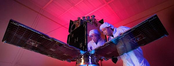
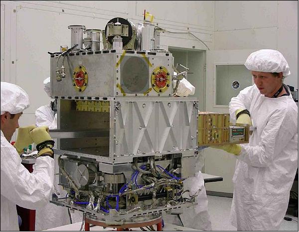
SSTL (Surrey Satellite Technology Ltd.), the contractor of LANL, is building the CFESat spacecraft as an enhanced microsatellite based on the SSTL-150 platform (formerly MicroSat-100 platform) designs of DMC (Disaster Monitoring Constellation) and TopSat; however, with deployed panels and long booms for the antennas. A contract award from LANL was signed by SSTL in March 2004. The spacecraft was delivered in 27 months using heritage satellite designs from Surrey's disaster monitoring constellation (DMC) and TopSat mission.
The spacecraft structure is of size 61 cm x 61 cm x 96.5 cm to fit within the ESPA (EELV Secondary Payload Adapter) volume requirements. [The ESPA system was designed within STP to take advantage of anticipated excess launch capacity on many of the DoD and commercial launches. ESPA exploits this unused payload margin by deploying up to six secondary payloads].The structure of CFESat employs Al and Al honeycomb panels, and includes a stack of MicroTray modules to mount the subsystems. The spacecraft employs an essentially cold biased, passive thermal control system with heater backup for emergency situations. Two body-mounted radiators are used to remove the excess payload heat.
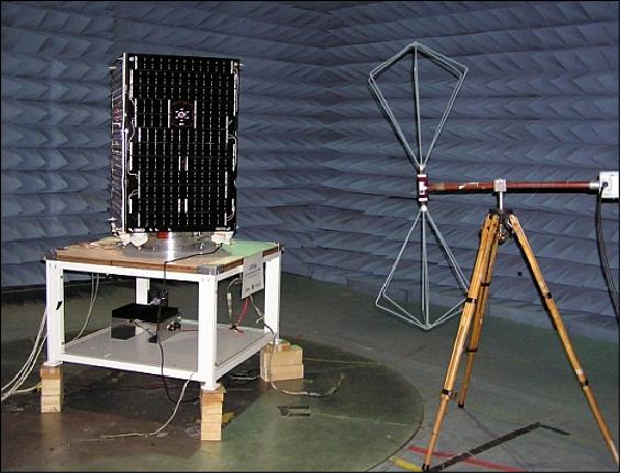
The S/C is 3-axis stabilized using a pitch momentum wheel and a yaw reaction wheel, along with dual redundant 3-axis magnetorquers as actuators. Pointing stability is maintained within ± 0.5o with pointing knowledge to 0.1o, provided by dual redundant star trackers (model: Altair HB star tracker developed by SSTL). 6)
A GPS receiver (SGR-10) is flown to aid navigation and to provide an accurate onboard timing function.
Power (110 W average with 30 W for the platform) is supplied by four deployable and two surface-mounted solar panels (triple-junction GaAs, 28 V unregulated bus + 5 V regulated bus). A Li-Ion battery of ABSL (UK) provides power during the eclipse phases of the orbit.
The C&DH (Command & Data Handling) subsystem employs a redundant CAN (Control Area Network) communication bus for all onboard communications. Two OBCs (386) are used in support of all spacecraft functions including file transfer and bootloading.
The mass of CFESat is 163 kg (32 kg of payload). The on-orbit lifetime is expected to be about 4 years.
Launch
A launch of CFESat took place on March 9, 2007 (UT) from Cape Canaveral, FLA (Atlas-5-401 launch vehicle). CFESat is a secondary payload on the STP-1 mission of DoD. The primary payload on this flight was OE (Orbital Express). The other secondary payloads were: MidSTAR-1, STPSat-1, and FalconSat-3. 7)
Orbit: Near-circular non-sun-synchronous orbit, altitude = 560 km, inclination = 35.4o, period of 95.9 minutes.
Note: The STP-1 mission had to deal with the deployment of five satellites into two orbital planes at two different altitudes. The Orbital Express (prime payload) and MidSTAR-1 spacecraft were deployed in the first orbital plane at an altitude of 492 km and an inclination of 46o. After two more centaur burns, the remaining ESPA payloads, STPSat-1, CFESat, and FalconSat-3, were inserted into the second orbital plane at an altitude of 560 km and an inclination of 35.4o. CFESat-1 was successfully released at T+61 minutes into the flight.
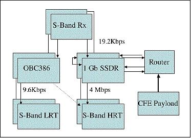
RF communications: CFESat employs two SSDRs (Solid State Data Recorder), each of 1 GByte capacity. A new router system is used to collect the downlink as well as the uplink data. All data transfer is provided in S-band with CPFSK (Continuous Phase Frequency Shift Keying) modulation and a data rate of 19.2 kbit/s in uplink. The downlink has data rates of 38.4 kbit/s or of 4 Mbit/s using QPSK (Quadra-Phase Shift Keying) modulation.
CFESat employs the IP (Internet Protocol) communications standard for all routine operations (as being implemented on all SSTL missions since the introduction of the DMC series). CFESat employs HDLC framing, with frame relay and IP on top. The ground segment at LANL uses the standard Cisco equipment to interface to the operations center.
The ground station is located at LANL using a 3.7 m dish antenna in support of all spacecraft monitoring and control functions and for all data reception and processing.
Mission Status
• In March 2015, the CFESat mission is still operational although it has technically been decommissioned. It continues to gather single-event upset data for the FPGAs. The project is not receiving funding, still some project people continue to look at the upset data (information provided by Mike Wirthlin, Brigham Young University). 8)
- Since its launch, CFESat has received configuration data from the ground many times, both refining and increasing the portfolio of experiments within the reconfigurable payload. Several CFE signal processing payload experiments have been uploaded to the reconfigurable platform and executed on the FPGAs. These signal processing experiments interface directly to the on-board ADC to process sampled data from the satellite antennae. Examples of this class of circuits that have been run on the satellite include several software defined radios (SDR), demodulators, decoders, and high-throughput FFT engines that exceeded a sustained computation rate of 10 GOPS (Giga Operations Per Second). CFESat has effectively demonstrated the benefits of deploying high-performance reconfigurable computing in space craft and the feasibility of operating the FPGAs in the presence of single-event upsets. 9)
• The CFESat spacecraft is operating in 2009.
- Unfortunately, because of the star camera "powered on exposure to the sun" - due to the loss of attitude control during the numerous on-board computer crashes and rebooting, the star cameras are now only able to detect stars during daylight periods. Thus, nominally for up to 60% of the orbit, the attitude control system is incapable of maintaining the original design pointing stability with magnetometers alone. 10)
- Due to an underperformance of the power system as well as recent loss of power production due to attitude instability, power management to maintain the battery voltage above 50% depth of discharge requires the payload to be turned off essentially every orbit when the solar beta angle is less than ± 20o, even when the payload is only in the nominal 55 W SEU (Single Event Upset) detection mode during the rest of the orbit.
- Unfortunately, only one of the three antenna masts inflated correctly, potentially due to the RF cable bundle being too tightly constrained interior to the antenna masts. The other two masts inflated about half way before they stalled and vented, leaving the antenna elements in a non-optimal orientation (Ref. 10).
• Since its launch, the CFE (Cibola Flight Experiment) has received configuration data from the ground more than three dozen times, both refining and increasing the portfolio of experiments within the reconfigurable payload. Over 30,000 experiments have been performed, where an experiment is the configuration of one or more Virtex devices and collection of data that is transmitted to the ground. CFESat, as a technology pathfinder, has effectively demonstrated the importance of high-performance reconfigurable computing. (Ref. 10).
• The reconfigurable computing architecture within CFE has performed very well and continues to be used for a number of reconfigurable computing experiments. Future experiments include both real-time SEU mitigation tests and other signal processing tests. 11)
- The nine Xilinx Virtex FPGAs used in the payload have been used for several high-throughput sensor processing applications and for single-event upset (SEU) monitoring and mitigation. The tests were conducted by LANL and by the NSF Center for High-Performance Reconfigurable Computing (CHREC) at Brigham Young University, Provo, UT, USA.
- Several CFE signal processing payload experiments have been uploaded to the reconfigurable platform and executed on the FPGAs. These signal processing experiments interface directly to the on-board ADC to process sampled data from the satellite antennae. Examples of this class of circuits that have been run on the satellite include several software defined radios (SDR), demodulators, decoders, and high-throughput FFT engines that exceeded a sustained computation rate of 10 GOPS (Giga operations per second). The performance of the payload is two to three orders of magnitude better than what can be expected from radiation hardened microprocessors.
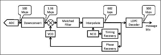
- One of these signal processing experiments is a 500 kbit/s QPSK receiver implemented on a single FPGA of the CFE reconfigurable computer (Figure 8). The purpose of this experiment was to demonstrate a practical application using the CFE's radio receiver and computing hardware. The experiment was successfully deployed and tested on-orbit in November 2008. A 500 kbit/s link was established between a transmitting ground station and CFE, with error free communication during the majority of the pass (Ref. 11).
• Following confirmation of separation of the launch vehicle, the ground station established contact with CFESat on the first visible pass. 12)
Experiment Complement (CFE)
The payload was designed and developed at LANL (Los Alamos National Laboratory), a facility operated by the University of California for the NNSA (National Nuclear Security Agency). 13) 14) 15)
CFE (Cibola Flight Experiment) - Software radio for spectrum monitoring
The primary objective is to demonstrate the space utility of FPGAs by testing several different types of upset mitigation schemes as well as to characterize the robustness of these chips over a wide temperature range. Six FPGAs were integrated onto CFESat. Six Sigma, a division of Winslow Automation, Inc., reconfigured the FPGAs for LANL to allow these components to withstand extreme thermal cycling while the satellite monitors weather patterns. Columnized FPGAs are being utilized which are commonly known as CGA (Column Grid Array). The same Six Sigma SolderQuik® technology is also an integral part of numerous other military and aerospace programs. LANL representatives refer to the experimental satellite as a "super computer in space," since the FPGAs can be reprogrammed and are radiation resistant. 16)
The LEO-to-ground radio link is highly dynamic. This is due to the large changes, relative to a stationary ground station, in signal propagation distance, antenna pointing, and sky noise during a typical twelve minute satellite pass. Traditional approaches to radio design assume worst-case operating conditions. This conservative design strategy can result in reliable and robust communications. But, due to the dynamic link this approach also leads to inefficient implementations because only a small fraction of the channel capacity is exploited. This is a severe limitation for small satellites due to restrictions on weight, volume, and power. 17)
CFE technology demonstration concept:
The goal is to demonstrate responsive, flexible, multi-mission RF payload with continuous data processing.
• FPGA based parallel computing offers 100 x performance advantage and adaptability
- Processing gain: ? greater sensitivity, data reduction in the downlink
- Reprogrammable: ? combats mission obsolescence, leverages new algorithms/targets after launch.
• Leveraging of COTS technology
- Reuse of commercial design tools, foundry, processes, masks
- Fabricated on epi substrate for SEL (Single Event Latchup) immunity
- Challenges: a) Single Event Upset must be handled at system level; b) Relatively high power density and complex packaging issues; c) Parallel computing not necessarily right hammer for all problems.
A further project objective is to add a radio to the input of the RCC (Reconfigurable Computer) onboard processor and to detect and measure impulse events (ionospheric lightning studies) occurring in a complex background.
The Software Radio elements are:
• Four channels 20 MHz bandwidth each
• Tunable from 100 to 500 MHz (wide band receiver)
• 300 GOP/s RCC (Re-Configurable Computer). Note: GOP (Groups of Pictures); the GOP is a group of successive pictures within an MPEG-coded video stream.
• Four-element antenna array.
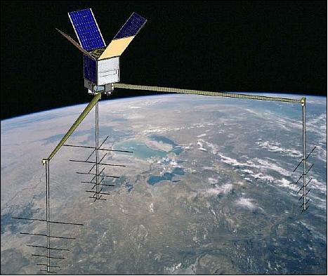
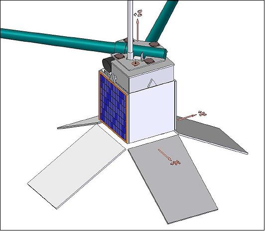
Four-element antenna array: The payload features also 4 LPA (Log-periodic Array Antenna) antennas built by L'Garde, Tustin, CA. Two crossed LPA antennas are mounted on the nadir deck of the S/C, and two single antennas are mounted to deployable booms (part of S/C bus, see Figure 1). Each antenna assembly has a mass of 2.1 kg and a size of 16 cm x 16 cm x 6 cm. Two telescoping booms are deployed from the spacecraft supporting the two single LPA payload antennas.
The antenna mast design was based upon the same inflatable mast structure that L'Garde designed and demonstrated on the ground for a NASA solar sail demonstration. Each antenna mast is comprised of a Kevlar fabric impregnated with a temperature sensitive, rigidizable resin that is deployed by inflation. Each antenna assembly weighed 2.1 kg and was approximately 16 x 16 x 6 cm in dimension when stowed. Inflated, each antenna was to be 2.4m in length.
Note: Unfortunately, only one of the three antenna masts inflated correctly, potentially due to the RF cable bundle being too tightly constrained interior to the antenna masts. The other two masts inflated about half way before they stalled and vented, leaving the antenna elements in a non-optimal orientation (Ref. 10).
The payload dimension are approximately 38 cm x 36 cm x 32 cm (Figure 9).
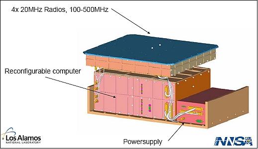
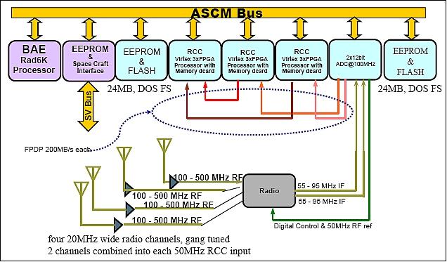
The payload consists of a power converter supply, radio tuners, and digital processing hardware including: ADCs (Analog Digital Converters), RCCs using Xilinx Virtex FPGAs, memory, communication interfaces, and a microprocessor (Rad6000).
The Rad6000 30 MHz microprocessor, a radiation hardened R6000 processor supplied by BAE, controls all of the payload digital modules and manages payload communications with the vehicle. The processor includes 8 MByte of radiation-hardened SRAM and executes the VxWorks operating system. Although this processor and its associated SRAM are radiation-hardened, the processor architecture is almost two decades old and does not have the computational power necessary to perform continuous real-time on-board sensor processing.
The payload uses both EEPROM and flash memory for nonvolatile storage. Three banks of 1 MByte of EEPROM are available to store the operating system and binary user code objects for the microprocessor. Two banks of flash memory (24 MByte each) store compressed configuration bitstreams used to configure the Xilinx Virtex devices. More than 20 uncompressed FPGA bitstream configurations can be stored in each flash memory module. ECC (Error Control Coding) is incorporated to mitigate SEUs that occur during read or write operations in the nonvolatile memory.
The RF VHF/UHF tuner was designed and built at Los Alamos. It includes four 20 MHz channels, each connected to a distinct LPA antenna, tunable in VHF and UHF bands, which can be "gang-tuned" by microprocessor command between 100 and 500 MHz. This configuration is designed to make high fidelity interferometric measurements from a single lightning pulse. All four RF channels have an instantaneous bandwidth of 20 MHz. Two RF channels are combined into each of the 50 - 100 MHz IF (Intermediate Frequency) ADC (Analog Digital Converter) input from all four antennas simultaneously to the reconfigurable processors.
The analog IF is sampled at 100 MHz with 12 bit resolution. The outputs from the payload ADCs are distributed across a network of point-to-point 200 MByte/s (32 bit x 50 MHz) LVTTL (Low Voltage Transistor-Transistor Logic) buses derived from the FPDP (Front Panel Data Port) specification.
ADC data cascades through the three reconfigurable computers. Two reconfigurable computers each receive one channel of ADC data for preliminary processing, while the third RCC combines the two intermediate results into a final measurement.
The processing payload was built around three reconfigurable computer (RCC) modules used to perform processing duties for a variety of experiments (Figure 11). Each RCC module uses three Xilinx Virtex XQVR1000 CG560 FPGAs as the data processors. The FPGAs are organized in a ring and each has identical pin definitions so they may share configuration files. This design strategy reduces the amount of nonvolatile memory needed for FPGA configurations, reduces the required uplink bandwidth, and provides for greater reliability through redundancy. In addition, complex designs only need to be designed and verified once thus reducing design time on the ground. The nine FPGAs provide over 9 million system gates and over 1 MByte of block RAM memory.
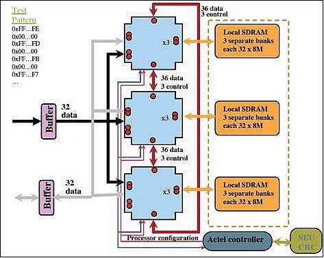
Each Virtex FPGA has 3 banks of independent memory; each bank is comprised of four Hyundai 64 MB SDRAMs organized as 8 M x 32-bit wide for a total of 288 MB per module. Each RCC module also has microprocessor access through a radiation tolerant Actel RT54SX32S device that acts as a microprocessor interface and board controller. The Actel FPGA provides watchdog monitoring for the three Xilinx FPGAs as well as a configuration interface, which aids in CFE's FPGA SEU mitigation scheme. While the use of Virtex FPGAs in this system may seem old when compared to FPGAs available today, the Virtex 1000 FPGA family was the most complex and dense FPGA available when the CFE system was first conceived. Since all satellite systems go through an extensive design, qualification, and testing procedure, the components used on orbiting satellites typically lag far behind the components available commercially. Furthermore, the Xilinx Virtex FPGA was the first SRAM-based FPGA to go through extensive reliability evaluation for radiation environments.
Instrument reconfiguration: Configuration of CFE from the ground offers an extremely flexible instrument for operating a variety of experiments. It also introduces complexity in the instrument, data transport, and data management at the ground station. To conduct each experiment, unique software runs on the Rad6000 microprocessor, unique configuration bitstreams are loaded into the Virtex FPGAs, unique SEU CRC codebooks are loaded into the SEU detection circuit, and unique telemetry packets are transmitted to the ground station which must be able to process the unique packets. This represents a large amount of complexity and can introduce risk. The risk can be tolerated on the instrument because the vehicle can reset or power cycle the instrument. Further, the instrument can boot directly from the vehicle mass memory if the internal nonvolatile memory is corrupted.
This complexity is managed by building flexibility into the entire system architecture: dynamic linking, dynamic command dictionaries, on-board storage of configurations, and hierarchical telemetry packet structures.
One unique feature of the software architecture is the ability to dynamically link object code while in orbit. This is an unusual feature for software designs operating in space, but it allows new software to be uploaded without reloading unchanged software components. The base operating system, command processors, and SOH tasks are linked together into a single image. Application specific code is uploaded and stored separately, then linked dynamically at execution time. This allows the uplink communications channel to be used efficiently by eliminating the need to upload unchanged software. This dynamic object linking also allows the processor RAM to be conserved by only linking code for the currently running experiment rather than linking code from all experiments.
The CFE software architecture also supports an unusual dynamic command dictionary. The command dictionary has approximately 75 static commands defined. This dictionary has a command that inserts (and removes) additional commands into a table that can support up to 1024 commands. This allows operators and designers to conceive of new experiments, upload the object code, FPGA configurations, and insert new commands in the dictionary to execute the new experiment. These features enhance reliability by preventing bugs from migrating into the operational codes during whole system rebuilds (Ref. 10).
Key observations of CFE
• Recognition of extreme dynamics of LEO communications link
- Traditional approach targets worst case channel conditions but never exploits best case – leaving most of the channel capacity unused!
• Elegant use of adaptability
- Use software defined radio concepts
- Improve channel utilization
• Complex acquisition algorithms implemented on ground segment
- Reduces space segment complexity
- Exploits FPGA based DSP for extreme performance.
The goal is to introduce these Cibola technology demonstration results into the smaller nanosatellite class for much better downlink capacities.
Introduction of new technologies: As a pathfinder mission, CFESat carries eight new technologies for space flight validation, including a supercomputer equipped with field-programmable gate arrays (FPGAs), a new power supply, inflatable antennas, deployable booms, a new type of launch-vehicle separation system, and a high-density pack of AA lithium-ion batteries. 18)
References
1) D. Roussel-Dupre, M. Caffrey, J. Buckley, P. Davies, "Cibola Flight Experiment," Proceedings of AIAA/USU Conference on Small Satellites, Logan, UT, Aug. 9-12, 2004, SSC04-VI-2, URL: http://digitalcommons.usu.edu/cgi/viewcontent.cgi?article=1706&context=smallsat
2) N. Ambrosiano, "Supercomputing satellite hits the road," Aug. 31, 2006, URL: http://www.lanl.gov/news/index.php?fuseaction=home.story&story_id=8916
3) D. Roussel-Dupre, M. Caffrey, J. Buckley, P. Davies, M. Sweeting, " "Cibola Flight Experiment," Proceedings of 55th IAC (International Astronautical Congress) 2004, Vancouver, Canada, Oct. 4-8, 2004, IAC-04-IAA.4.1.1.6
4) "Los Alamos and Surrey Satellite contract for Cibola flight experiment platform,", URL: http://www.lanl.gov/news/index.php/fuseaction/home.story/story_id/1536
5) P. Davies, D. Liddle, J. Buckley, M. Sweeting, D. Roussel-Dupre, M. Caffrey, "A modular design for rapid-response telecoms and navigation missions," Proceedings of The 4S Symposium: Small Satellites, Systems and Services (ESA SP-571), Sept. 21-24, 2004, La Rochelle, France
6) P. Oosthuizen, S. Fellowes, C. Collingwood, S. Lalani, A. Cropp, S. Gleason, "Development and On-Orbit Results of the SSTL Low Cost Commercial Star Tracker," AIAA Guidance, Navigation, and Control Conference and Exhibit, Aug. 21-24, 2006, Keystone, CO, USA, paper: AIAA 2006-6045
7) "Cibola Flight Experiment launches on Atlas-5 rocket," LANL; March 12, 2007, URL: http://www.lanl.gov/news/index.php/fuseaction/home.story/story_id/9897
8) Tom Davidson, Elias Vansteenkiste, Karel Heyse, Karel Bruneel, Dirk Stroobandt , "Identification of Dynamic Circuit Specialization Opportunities in RTL Code," ACM Transactions on Reconfigurable Technology and Systems (TRETS), Vol. 8, Issue 1, Feb. 2015
9) M.J. Wirthlin, "FPGAs operating in a radiation environment: lessons learned from FPGAs in space," Topical Workshop on Electronics for particle physics 2012, Sept. 17-21, 2012, Oxford, UK, Published in Feb. 2013, URL: http://iopscience.iop.org/1748-0221/8/02/C02020/pdf/1748-0221_8_02_C02020.pdf?origin=publication_detail
10) Michael Caffrey, Kim Katko, Anthony Nelson, Joseph Palmer, Scott Robinson, Diane Roussel-Dupre, Anthony Salazar, Michael Wirthlin, William Howes, Daniel Richins, "The Cibola Flight Experiment," Proceedings of the 23nd Annual AIAA/USU Conference on Small Satellites, Logan, UT, USA, Aug. 10-13, 2009, SSC09-III-6, URL: http://digitalcommons.usu.edu/cgi/viewcontent.cgi?article=1277&context=smallsat
11) Michael Caffrey, Michael Wirthlin, William Howes, Daniel Richins, Keith Morgan, Diane Roussel-Dupre, Scott Robinson, Anthony Nelson, Anthony Salazar, "On-Orbit Flight Results from the Reconfigurable Cibola Flight Experiment Satellite (CFESat)," IEEE Symposium on Field-Programmable Custom Computing Machines (FCCM2009), Napa, CA, USA, April 5-7, 2009, URL: https://web.archive.org/web/20180722021208/http://www.chrec.org/pubs/B3_FCCM09.pdf
12) P. Davies, D. Roussel-Dupre, M. Sweeting, "In-Flight Experience of the Cibola Flight Experiment Satellite," 58th IAC (International Astronautical Congress), International Space Expo, Hyderabad, India, Sept. 24-28, 2007, IAC-07-B4.4.01
13) Michael Caffrey, Keith Morgan, Anthony Salazar, Diane Roussel-Dupre, "Results from the Cibola Flight Experiment's 1st Year," Proceedings of MAPLD 2008 (Military and Aerospace Applications of Programmable Devices and Technologies), Annapolis, MD, USA, Sept. 15-18, 2008, LA-UR-08-05478, URL: http://nepp.nasa.gov/mapld_2008/presentations/w/01%20-%20Caffrey_Michael_mapld08_pres_1.pdf
14) Brian Pratt, Michael Wirthlin, Michael Caffrey, Paul Graham, Keith Morgan, "Analysis of SEU-induced Errors in an FPGA-based Digital Communications System," Proceedings of MAPLD 2008, Annapolis, MD, USA, Sept. 15-18, 2008, LA-UR-08-05478, URL: http://nepp.nasa.gov/mapld_2008/presentations/w/06%20-%20Pratt_Brian_mapld08_pres_1.pdf
15) Eric Johnson, Michael Caffrey, Paul Graham, Nathan Rollins, Michael Wirthlin, "Accelerator Validation of an FPGA SEU Simulator," LANL, 2003, LA-UR-03-5062, URL: http://www.rasr.lanl.gov/RadEffects/publications/NSREC_2003_validation_poster.pdf
16) "Experimental Satellite Integrates SIX SIGMA CGA," May 11, 2007, URL: http://ap.pennnet.com/display_article/292487/36/ARTCL/none/none/Experimental-Satellite-Integrates-SIX-SIGMA-CGA/
17) Michael Caffrey, Joseph Palmer, "Exploiting Link Dynamics in LEO-to-Ground Communications," Proceedings of the 2009 CubeSat Developers' Workshop, San Luis Obispo, CA, USA, April 22-25, 2009, URL: http://mstl.atl.calpoly.edu/~workshop/archive/2009/Spring/Session%204%20-%20CubeSat%20Communications/1015-Caffrey-Link%20Dynamics.pdf
18) http://www.lanl.gov/news/index.php/fuseaction/home.story/story_id/9899
The information compiled and edited in this article was provided by Herbert J. Kramer from his documentation of: "Observation of the Earth and Its Environment: Survey of Missions and Sensors" (Springer Verlag) as well as many other sources after the publication of the 4th edition in 2002. - Comments and corrections to this article are always welcome for further updates (eoportal@symbios.space).
Overview Spacecraft Launch Mission Status Experiments References Back to top