CASSIOPE (Cascade SmallSat and Ionospheric Polar Explorer)
EO
Operational (extended)
Space environment
Magnetic field
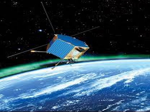
Launched in September 2013, CASSIOPE (Cascade SmallSat and Ionospheric Polar Explorer) is a technology demonstration program facilitated through a public-private partnership of the Canadian Space Agency (CSA) and Industrial Technologies Office (ITO). It is a three part mission, with the cascade payload demonstrating the world’s first commercial space-based digital courier service, the ePOP (Enhanced Polar Outflow Probe) measuring the interaction of the Earth’s upper atmosphere with the solar wind, and new minisatellite bus that may be used for future missions.
Quick facts
Overview
| Mission type | EO |
| Agency | CSA, MDA, University of Calgary |
| Mission status | Operational (extended) |
| Launch date | 29 Sep 2013 |
| Measurement domain | Gravity and Magnetic Fields |
| Measurement category | Gravity, Magnetic and Geodynamic measurements |
| Measurement detailed | Magnetic field (vector), Neutral Particle Composition and Flow Velocity, Electron density profile, Ion Density, Drift Velocity, and Temperature, ULF-HF Electromagnetic Waves, Auroral Emissions, Electron Energy and Pitch Angle Distribution |
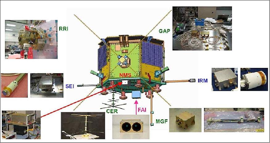
| Instruments | CER, IRM, NMS, SEI, GAP, RRI, MGF, FAI |
| Instrument type | Space environment, Magnetic field |
| CEOS EO Handbook | See CASSIOPE (Cascade SmallSat and Ionospheric Polar Explorer) summary |
Summary
Mission Capabilities
CASSIOPE carries ten instruments for various applications. . IRM (Imaging and Rapid-Scanning Ion Mass Spectrometer) observes mass composition and 3D velocity distributions of ions, while SEI (Suprathermal Electron Imager) measures 2D energy and angular distributions of thermal electrons and soft electrons. FAI (Fast Auroral Imager) images auroral emissions in the near infrared (NIR) and visible (VIS) spectral ranges. NMS (Neutral Mass and Velocity Spectrometer) measures the density and velocity of neutral atmospheric species and MGF (Magnetic Field Instrument) characterises electric currents flowing to and from the high latitude (auroral) ionosphere. RRI (Radio Receiver Instrument) measures radio waves in the ULF and HF frequency range. GAP (GPS Attitude and Position Experiment) and CER (Coherent Electromagnetic Radiation) both measure total electron content (TEC) of the ionosphere, while GAP also measures S/C velocity and attitude. CX (Cascade Experiment) is part of the courier mission, and is an advanced satellite communication demonstration payload to develop and demonstrate key Cascade enabling technologies and also to demonstrate the feasibility of the large file, end-to-end transfer method. The PCPMU (Payload Controller, Processor, and Memory Unit) controls payloads, power, echo or replica data processing, image data compression for optical missions, and on-board data processing.
Performance Specifications
IRM observes ions in the energy range of 0.1 - 100 eV and 1 - 40 amu/q. It has a data rate of 0 - 300 kwords/s. SEI measures electrons in the range 1 - 200 eV at an imaging rate of 100 Hz. IRM and SEI operate within a field of view of 130° and 360°, respectively. FAI generates 16 bit digital images at a rate of one per second in the NIR band and two images per minute at the 630 nm band. SEI, FAI, and NMS all employ 256 x 256-pixel CCD detectors. MGF detects 0.1 μAm-2 currents or stronger at 100 m or larger, with a precision of 21 bits, a resolution of approximately 0.0625 nT, a dynamic range of ±65,536 nT, 160 Hz sampling rate, and a variable tilt up to 2° or 3°. RRI operates within a dynamic range of 120 dB above an input threshold of 0.3 μV. CER transmits three beacon signals near 150, 400, and 1066 MHz within the VHF/UHF bands, and the CX processes 50 - 500 GByte/day at a rate of 350 Mbit/s. The PCPMU can store 1 Tbit of data and transfer data at a rate of 0.7 Tbit/s.
CASSIOPE follows an elliptical polar orbit at an altitude of 325 x 1500 km, an inclination of 81°, and a period of 103 minutes.
Space and Hardware Components
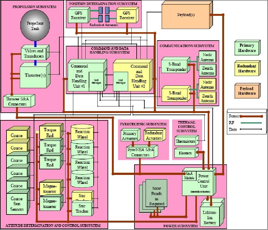
Three-axis stabilisation is achieved by the ADSC (Attitude Determination and Control Subsystem), whereby attitude is sensed with a μASC (Micro Advanced Stellar Compass), CSS (Coarse sun sensors), and magnetometers, while actuation is provided by torque rods and four reaction wheels. The spacecraft is built on a MAC-200 (Magellan Aerospace Corporation - 200) bus, also known as an MMSSB (Multi-Mission Small Satellite Bus) in Canada. Thermal control is achieved by primarily passive means, but also through the use of software-controlled operation heaters for the non-essential power bus and thermostatically controlled survival heaters for the essential power bus. Information and control is commanded by the C&DH (Command and Data Handling) subsystem, and power is provided by the EPS (Electrical Power Subsystem). The EPS consists of triple-junction surface-mounted solar cells and multiple strings of Lithium-Ion cells. RF communication is in S-band for uplink at 125 kbit/s and Ka-band for downlink at 1.6 - 4 Mbit/s.
In February 2018, CASSIOPE joined three other observational satellites to create the four-satellite Swarm mission that has the aim of vastly improving our understanding of space weather and features such as the aurora borealis.
CASSIOPE (Cascade SmallSat and Ionospheric Polar Explorer)
Spacecraft Launch Mission Status Sensor Complement e-POP Instruments
Ground Segment References
CASSIOPE is a new generation of small-satellite and multifunctional platform technology demonstration program of CSA (Canadian Space Agency) and ITO (Industrial Technologies Office) with the goal to serve both, namely scientific and commercial support applications in a variety of future Canadian space missions. The program is based on a PPP (Public Private Partnership) consortium - and developed under a Contribution Agreement between CSA, TPC (Technology Partnerships Canada), the University of Calgary, and MDA (MacDonald, Dettwiler and Associates). 1) 2) 3) 4) 5) 6) 7) 8)
The objectives call for a three-part mission:
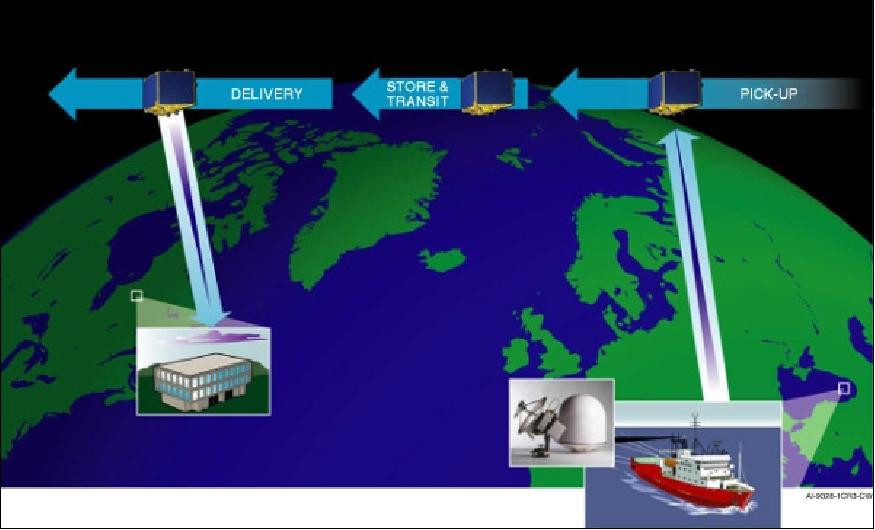
1) Courier in the sky service: This involves an experimental payload, named Cascade, to demonstrate the world's first commercial space-based digital courier service based on store & forward file transfer techniques for message transfer. Cascade is designed to deliver data files of a size between 50 - 500 Gbyte at transmission speeds of 1.2 Gbyte/s over Ka-band when a ground station is within view of the spacecraft.
2) The science mission, called ePOP (Enhanced Polar Outflow Probe), is comprised of eight instruments. The objective is to measure the interaction of the Earth's upper atmosphere with the solar wind (space weather monitoring with greatly improved prediction capability). The ePOP team is comprised of scientists and engineers from Canadian universities and three research organizations: the University of Calgary (lead organization), York University, the Universities of Alberta, Athabasca, Saskatchewan, Western Ontario, and New Brunswick. The Communications Research Center (CRC), located in Ottawa, as well as ISAS (Institute of Space and Astronautical Science) of, Tokyo, Japan and the US NRL (Naval Research Laboratory) are also partners in the project.
3) Platform demonstration: The mission serves as a testbed for a Canadian spacecraft bus and subsystem functionality. The generic platform is considered for total mass budgets of 350-500 kg. The main goal of the program is to develop a minisatellite bus that may be used for future missions, including Earth observation, communications, space research and exploration.
CSA selected MDA Ltd. of Richmond, BC as the prime contractor for the space and ground infrastructure of the CASSIOPE Mission, including system engineering, design, assembly, integration, testing, launch and operation of the spacecraft. Within this context, Bristol Aerospace of Winnipeg, Manitoba, was selected to provide a preliminary design of a cost-effective multipurpose platform.
Under the Contribution Agreement, the University of Calgary will have ownership of the e-POP instrument payload while MDA will operate it, the CASCADE payload, and the CASSIOPE bus.
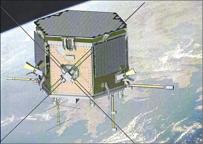
Spacecraft
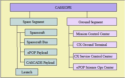
The CASSIOPE system is composed of a minisatellite space segment and the associated ground segment. The so-called SmallSat bus structure is a CSA-sponsored initiative, a generic design approach for multimission functionality under development at Bristol Aerospace, a division of MAC (Magellan Aerospace Corporation). The spacecraft bus is referred to as MAC-200 (a generic bus of SciSat-1 flight heritage - which used the MAC-100 bus). The bus utilizes a fully redundant cross-strapped architecture and is capable of providing mission lifetimes of up to 7 years. CASSIOPE is the first mission to use the MAC-200 bus. Note: In the meantime, the MAC-200 bus is also known in Canada as the MMSSB (Multi-Mission Small Satellite Bus). 9) 10) 11) 12)
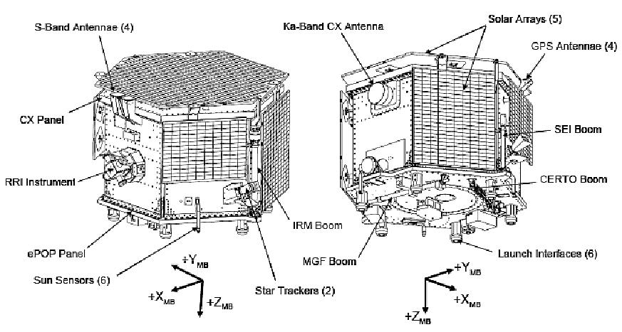
The spacecraft structure is made up of aluminum honeycomb panels with aluminum face sheets, held together with machined aluminum brackets and stringers. Aluminum inserts are bonded into the panels to fasten down bus and payload units. The structure is held together with stainless steel fasteners. The spacecraft is of hexagonal shape with a diameter of 1.8 m and a height of 1.4 m. The spacecraft has a total mass of ~490 kg and a design life of 2 years.
The spacecraft is 3-axis stabilized. The ADCS (Attitude Determination and Control Subsystem) is designed as a zero-momentum system. Attitude is sensed with the µASC (Micro Advanced Stellar Compass) of DTU (Danish Technical University), CSS (Coarse Sun Sensors), and magnetometers; actuation is provided by 4 reaction wheels and torque rods. The MAC-200 bus provides an autonomous, active safe-hold mode to keep the spacecraft power-positive in the vent of an onboard anomaly detection. A passive safe hold can also be provided that can function without the ADCS. Use of nadir-ram or latitude-longitude target slewing.
Thermal subsystem: Thermal control of the bus is primarily passive, supplemented with software-controlled operational heaters operating off the non-essential power bus. Thermostatically controlled survival heaters operate off the essential power bus. The equipment heat is rejected from strategically placed radiator surfaces along the bus hex sidewalls. MLI (Multilayer Insulation) radiatively isolates the spacecraft from solar heating and deep space cooling, and component-to-component heat transfer, as required.
The C&DH (Command & Data Handling) subsystem consists of:
- A standard cPCI (Compact Peripheral Component Interface) bus that allows for future expendability of all cards on the bus and selection of external card manufacturers that support the cPCI bus
- Standard enclosure/backplane
- The C&DH subsystem is comprised of a controller card (CC), a data handling card, A PSC (Power Supply Card), an IOC (Input/Output Card), and MIC (Mission Interface Card). The MIC is specific to each mission and can be adapted, removed, or several can be included according to mission specific requirements.
- The controller card has a PowerPC processor with several MB of RAM and EEPROM, which provides ample processing power and memory margins for current and future software.
- Development of all software (flight, ADCS, and payload handling) on a single platform (PowerPC with VxWorks).
- The CASSIOPE mission does not have a propulsion system.
The EPS (Electric Power Subsystem) uses triple-junction surface-mounted solar cells (InGaP/GaAs/Ge) of Emcore with a power conversion efficiency of 27% (panels on 5 sides of the S/C). The battery is based on multiple strings of Lithium-ion cells placed 8 in series to generate a fully charged bus voltage of 33.6 V. The EPS provides an unregulated bus voltage at 28V ±6 V DC (payload power of up to 130 W average).
RF communications: Communications are provided via S-band (TT&C + ePOP) and Ka-band (350 Mbit/s). The protocol is CCSDS compatible. The spacecraft supports half-duplex transmission and reception of user data (large data packages) to and from the CX ground terminal over the Ka-band link. TT&C data rates are 125 kbit/s uplink and 1.6 - 4 Mbit/s in downlink.
Spacecraft stabilization | 3-axis stabilized, zero momentum |
Momentum management | Reaction wheels and magnetic torque rods |
Attitude control | ±0.04º (3σ) in pointing, including biases |
Attitude knowledge | ±0.015 º (3σ) |
Orbit knowledge | Position: ±10 m (3σ) with GPS, velocity: +0.25 m/s (3σ) with GPS |
C&DH architecture | Power PC, up to 1600 MIPS, VxWorks and C++, cPCI peripherals |
Data downlink | S-band, bit rate programmable to 4 Mbit/s, CCSDS with optional Reed-Solomon and convolutional encoding |
Command uplink | S-band, 4 kbit/s |
Cascade data downlink | Ka-band, > 300 Mbit/s |
E-POP dtata storage | Up to 1.5 GB/orbit |
Spacecraft mass, size, power | ~500 kg, 1.8 m ∅ x 1.4 m, up to 600 W (average) |
Launch
The CASSIOPE minisatellite was launched on Sept. 29, 2013 on a Falcon-9 launch vehicle of SpaceX. The launch site was VAFB, CA.The Falcon-9 used for this launch the new Merlin 1D engines which have not flown so far. This new configuration of the Falcon is designated as Falcon 9 v1.1. 13) 14) 15)
In 2011, CASSIOPE was in storage in Montreal awaiting its launch date, which will ultimately depend on the success of the upcoming Falcon launches.
The secondary payloads on this flight are:
• CUSat-1 and CUSat-2, microsatellites (each of ~41 kg) of Cornell University, Ithaca, N.Y.
• DANDE (Drag and Atmospheric Neutral Density Explorer), a microsatellite (<50 kg) of the University of Colorado at Boulder.
• POPACS (Polar Orbiting Passive Atmospheric Calibration Sphere). Three passive POPACS satellites were separated from a 3-Unit CubeSat dispenser installed on the second stage. The dispenser system released three independent spherical satellites immediately after deployment into an identical orbit.
POPACS is a collaborative a 3U CubeSat mission of several US universities and entities including: MSU (Morehead State University), Gil Moore (POPACS Project Director), the University of Arkansas, PSC (Planetary Systems Corporation), Silver Spring, MD, MSU (Montana State University), Drexel University (Philadelphia), et al.
Orbit: Elliptical polar orbit, 325 km x 1500 km, inclination =81º, period = 103 minutes (14 orbits/day).
Mission Status
• April 5, 2018: On 17 December 1971, scientists observed a bizarre new phenomenon in the outermost region of Earth's atmosphere, where the planet's magnetic field orchestrates the flow of charged particles and produces such phenomena as auroras. In the midst of a massive geomagnetic storm induced by a surge of solar radiation, satellites detected large flows of heavy oxygen (O+) ions streaming away from Earth, seemingly in defiance of gravity. Ever since, scientists have been trying to figure out what propelled the ions, in part because disturbances in this zone—known as the ionosphere—can disrupt communication systems. A new study by Yangyang Shen et al. reveals for the first time how low-altitude electromagnetic waves help launch these ions toward outer space. 16) 17)
- Normally, the upward diffusion of O+ ions in Earth's ionosphere is balanced by gravity, resulting in a state of equilibrium. Surges of energy from the Sun can disrupt this balance, however, causing flows of plasma that can hurtle outward like a fountain, then fall back toward Earth. To investigate how O+ ions become energized enough to escape Earth's gravity, the researchers used measurements from the Canadian CASSIOPE satellite. One of CASSIOPE's missions is to become the world's first commercial space-based digital courier service, picking up and dropping off massive packages of digital data all over the globe. Another is to collect data on solar storms in the upper atmosphere using the Enhanced Polar Outflow Probe (e-POP) payload, a collection of eight instruments that can, among other capabilities, measure the energy distribution of ions in the ionosphere and image auroral emissions.
- Over the course of 1 year, the authors observed e-POP measurements at relatively low altitudes, between 325 and 730 kilometers. They looked for hot spots in the ionosphere, which occur when O+ ions become energized enough to escape Earth's gravitational field. The team analyzed 24 such hot spots, examining their relation to the bulk flow of ions along the magnetic field lines around Earth, as well as low-frequency electromagnetic waves and currents.
- In the first statistical study of its kind, the team observed that extremely low frequency electromagnetic waves known as BBELF (BroadBand Extremely Low Frequency) waves energize O+ ions, even at relatively low altitudes, heating them and accelerating them outward. This phenomenon, called transverse ion heating, has long been thought to occur predominantly at higher altitudes—not as low as 350 kilometers, as the authors observed. The researchers discovered patches of ionosphere where this heating was particularly intense, reaching up to 4.5 eV (50,000 K) in areas about 2 kilometers across, they report.
- Researchers traditionally have attributed heating in the lower reaches of the ionosphere to frictional interaction with Earth's atmosphere, but the new study suggests that electromagnetic waves can also cause heating events. The study also reported downward flowing jets of ionospheric ions, which the authors attribute to downward pointing electric fields associated with auroral currents.
• February 22, 2018: With the aim of making the best possible use of existing satellites, ESA and Canada have made a deal that turns Swarm into a four-satellite mission to shed even more light on space weather and features such as the aurora borealis. 18)
- Canada's Cassiope satellite carries three instrument packages, one of which is e-POP (Enhanced Polar Outflow Probe). It delivers information on space weather which complements that provided by Swarm. Therefore, the mission teams began looking into how they could work together to make the most of the two missions.
- To make life easier, it also just so happens that Cassiope's orbit is ideal to improve Swarm's readings.
- And now, thanks to this international cooperation and formalized through ESA's Third Party Mission program, e-POP has effectively become a fourth element of the Swarm mission. It joins Swarm's Alpha, Bravo and Charlie satellites as Echo.
• January 28, 2018: An ongoing question in space physics is whether the energy that powers the vibrant and dynamic aurora is the result of static electric fields or magnetic waves. We address this question using data from three observational satellites, e-POP, Swarm A, and Swarm C. We compare electric and magnetic field measurements at the locations of the spacecraft to high-speed images of the aurora below as the satellites traveled over northern Canada. We show that as the satellites traveled over the aurora they detected magnetic waves known as Alfvén waves. We argue that these waves play an important and underappreciated role in transporting energy from near-Earth space to the atmosphere in order to power the aurora. 19)
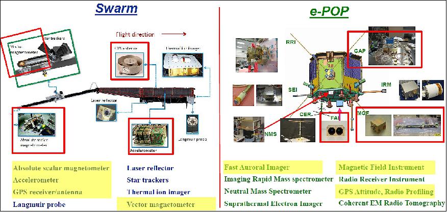
• March 2017: Between the Swarm and e-POP missions, there is a strong overlap in Magnetic Field and MIT (Magnetosphere-Ionosphere-Thermosphere) Coupling! 20)
Swarm[Friis-Christensen et al., 2008] | e-POP[Yau and James, 2015] |
• Earth's magnetic field and its temporal evolution with unprecedented accuracy | • Micro-scale plasma outflow, neutral escape in polar ionosphere; auroral currents, acceleration |
• Core dynamics, geo-dynamo processes, core-mantle interaction | • Topside ion upflow and acceleration |
• Map lithospheric magnetization; its geological interpretation | • Thermospheric heating and escape |
• Determine 3-D electrical conductivity of the mantle | • Auroral currents and acceleration |
• Investigate electric currents in the magnetosphere and ionosphere | • Radio wave propagation |
| • Active ionospheric heating |
Synergistic Swarm/e-POP 1) Magnetic field: Auroral dynamics, field aligned current; contribute to main field modeling 2) Ionosphere-Thermosphere (IT): Neutral density variations, plasma irregularities; IT coupling 3) Magnetosphere-Ionosphere (MI): Electrodynamics of auroral arcs, MI coupling (MIC) | |
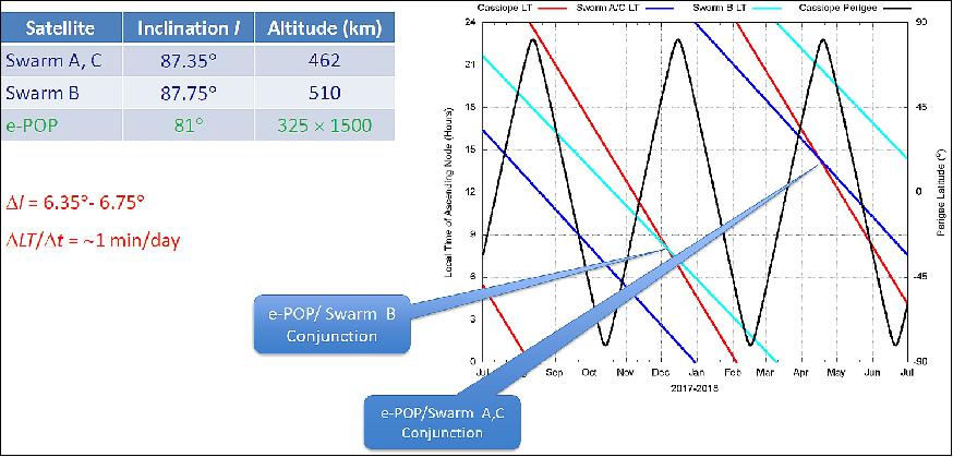
• New synergistic studies on magnetosphere-ionosphere-thermosphere (MIT) coupling - Complementary nature of orbital (altitude and local time) coverage - Unique e-POP measurement capabilities part of added component to Swarm constellation • Coordinated e-POP (MGF, GAP, FAI etc.) operation with Swarm enable new studies - Earth's magnetic field and current systems: magnetic field perturbations at high latitudes, small scale structures, altitude distribution and longitudinal extent - Upper atmospheric dynamics: thermospheric density variations, plasma density irregularities, density forecasts for orbit prediction - Auroral dynamics and related MIT coupling: electrodynamics of auroral arcs, MI coupling. • Contribute to two of Swarm's four primary research objectives - Advance knowledge on MIT coupling and space weather effects on Earth's magnetic field, ionosphere, and thermosphere |
• March 1, 2017: New research from DTU Space and the University of New Brunswick, NASA/JPL ( Jet Propulsion Laboratory) and University of Illinois shows that, eruptions on the Sun's surface not only send bursts of particles into Earth's atmosphere, but—contrary to previous belief—also remove electrons across large areas. The new knowledge increases our understanding of solar storms and can contribute to more reliable communication and navigation in Arctic areas. 21)
- Eruptions on the Sun's surface send clouds of electrically charged particles towards Earth, producing solar storms that—among other things—can trigger the beautiful Northern Lights over the Arctic regions. But the storms may also have a strong impact on the efficiency of communication and navigation systems at high latitudes. It is therefore important to study the phenomena.
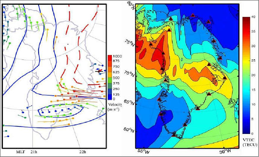
- A multi-instrumented approach is presented for the analysis of the Arctic ionosphere during the 19 February 2014 highly complex, multiphase geomagnetic storm, which had the largest impact on the disturbance storm-time index that year. The geomagnetic storm was the result of two powerful Earth-directed CMEs (Coronal Mass Ejections). It produced a strong long lasting negative storm phase over Greenland with a dominant energy input in the polar cap. The research team employed GNSS (Global Navigation Satellite System) networks, geomagnetic observatories, and a specific ionosonde station in Greenland. This was complemented with spaceborne measurements in order to map the state and variability of the Arctic ionosphere. In situ observations from the Canadian CASSIOPE (CAScade, Smallsat and IOnospheric Polar Explorer) satellite's ion mass spectrometer were used to derive ion flow data from the polar cap topside ionosphere during the event. 22) 23)
- "We made extensive measurements in connection with a specific solar storm over the Arctic in 2014, and here we found that electrons in large quantities are virtually vacuum-cleaned from areas extending over 500 -1,000 km. It takes place just south of an area with heavy increases in electron density, known as patches," says Professor Per Høeg from DTU Space.
- The results of the research were recently published on the front page of the renowned scientific journal Radio Science. The discovery is an important piece in the jigsaw puzzle of understanding solar storms and their impact on the Earth's ionosphere. "It's a surprising discovery that we hadn't anticipated. We can see that it happens, but we don't know why. However, other datasets from Canada indirectly support our new observations," says Per Høeg.
- Dramatic changes in magnetic field: The explanation of the phenomenon should probably be found in the geomagnetic processes in the Earth's magnetic field in a direction away from the Sun. The composition of the magnetic field undergoes dramatic changes in the area between the solar wind and the Earth's magnetic field, triggering powerful burst of energy.
- "The forerunner to the phenomenon is a violent eruption on the Sun's surface—also known as coronal mass ejections or CME, where bubbles of hot plasma and gas in the form of particles, electrons, and a magnetic field are hurled in the direction of the Earth," says Per Høeg.
- As the geomagnetic solar storm took place in the ionosphere over the Arctic in February 2014, it was measured via satellites and land-based measuring stations. Among other things, via the GPS network GNET in Greenland—which DTU helps run—via DTU's geomagnetic measuring stations, the global navigation system GPS, and various American and Canadian satellites. Thus, large data volumes from the solar storm were recorded.
• On September 29, 2016, CASSIOPE was 3 years on orbit. 24)
• May 2016: The initial, 18-month, science operation phase of CASSIOPE began in late November 2013, after the successful completion of the two-month commissioning phase, it was extended in May 2015 for 2 years to late May 2017. Several science investigations have been carried out to date, including the study of sub-decameter ionospheric structures in the topside ionosphere, small-scale aurora structures using auroral tomography, low-altitude polar wind, coordinated radio propagation experiments, and coordinated active heating experiments. A number of these investigations take advantage of the unique measurement resolution capabilities of the e-POP instruments, the onboard data storage capacity and telemetry bandwidth of the Cascade payload, and the versatile attitude pointing capability of the CASSIOPE spacecraft. 25)
• Feb. 3, 2016: CASSIOPE is currently in its extended mission operation phase and both, the spacecraft and all e-POP instruments, are currently operating nominally. 26)
• Sept. 29, 2015: Two years after launch CASSIOPE/e-POP continues to perform well in routine operations. All eight instruments are operational and new data is being collected daily. All e-POP data can be viewed and downloaded at the Canadian Space Science Data Portal. 27)
• March 25, 2015: Canada's CASSIOPE is making a significant contribution to unraveling the mysteries of space weather. To accomplish this feat, the satellite uses a dedicated scientific payload e-POP (enhanced Polar Outflow Probe), which observes the ionosphere. 28)
• Feb. 2014: Researchers at NASA/JPL in collaboration with the University of New Brunswick in Canada, studied irregularities in the ionosphere, a part of the atmosphere centered about 350 km above the ground that defines the boundary between Earth and space.The ionosphere is a shell of charged particles (electrons and ions), called plasma, that is produced by solar radiation and energetic particle impact. The new study, published in the journal Geophysical Research Letters, compares turbulence in the auroral region to that at higher latitudes, and gains insights that could have implications for the mitigation of disturbances in the ionosphere. 29)
Intermediate-scale plasma irregularities in the polar ionosphere are reported, inferred from high-resolution RO (Radio Occultation) measurements using GPS (Global Positioning System) to CASSIOPE satellite radio links. The high inclination of CASSIOPE and the high rate of signal reception by the GPS Attitude, Positioning, and Profiling RO receiver on CASSIOPE enable a high-resolution investigation of the dynamics of the polar ionosphere with unprecedented detail. 30)
Intermediate-scale, scintillation-producing irregularities, which correspond to 1 to 40 km scales, were inferred by applying multiscale spectral analysis on the RO phase measurements. Using the multiscale spectral analysis approach and satellite data, the researcher team discovered that the irregularity scales and phase scintillations have distinct features in the auroral oval and polar cap. The key findings are that large length scales and more intense phase scintillations are prevalent in the auroral oval compared to the polar cap implying that the irregularity scales and phase scintillation characteristics are a function of the solar wind and magnetospheric forcings.
• On Sept. 29, 2014, the CASSIOPE spacecraft was 1 year on orbit operating nominally.
• August 2014: The CASCADE CX payload has been commissioned and several demonstration experiments have occurred which have validated key enabling technologies and demonstrated the end-to-end transfers of very large data files. The results of these experiments have shown that a scaled up version of the CASCADE CX experimental payload could be built to support a composite 2.4 Gbit/s data transmission rate enabling the pickup/delivery of data at a rate in excess of 15 GB/minute of satellite access at a BER no worse than 1 x 10-17. 31) 32)
CX payload commissioning was interleaved with activities on Bus and ePOP subsystems, starting after confirmation of Bus thermal maintenance of the payload panel. Each unit was powered for the first time during a real-time pass with operators and a payload engineer in the command loop. In each case the unit was brought to an active state (stopping short of signal transmission or reception), and unit status and power telemetry were confirmed to be nominal. Units were checked in a sequence of logical groupings: PCS (Payload Control Software), Master Oscillator, Data Storage Unit, the receive chain (Demodulator and Frequency Generator) and the transmit chain (Modulator, TWTA, and waveguides). The PCS and the Master Oscillator were left active after status confirmation as this is the normal state for operations, while other units were powered off after their activity was complete. Finally, as a bridge to the CX demonstrations, short transmissions with breaks were scheduled on GT passes; although the GT was not used to send/receive data the procedure was able to confirm back orbit control and timing for future CX demonstration activities.
As a result of the demonstrations performed with the CX Payload, much of the technologies (both on-orbit and on the ground) and processes developed have been validated including:
- A proven Gigapackage format for transporting large amounts of data. A relatively high error level can be corrected in the files that are moved through the satellite, keeping the power and antenna size requirements on both the satellite and the ground terminals small.
- A proven technique for using a 30GHz beacon to assess the quality of a 20 GHz data link (and vice versa). By using a beacon to assess in real-time whether or not the link is in a fade, keeps power and antenna sizes on both the satellite and terminals can be kept much smaller than they would otherwise need to be.
- A qualified payload design. The architecture has been proven and critical units qualified (Modulator, Demodulator and DSU).
- A qualified Ground Terminal system design. Algorithms implemented on the existing Ground Terminal have been refined and validated, to be used as the core of any new Ground Terminals.
In addition to the technology validation, the CX Payload on CASSIOPE has also provided a benefit to the ePOP Science team. The ePOP Science team has been able to use the CX link to download additional science data that would have not been possible using the S-band link alone.
• The initial, 18-month, science operation phase of CASSIOPE began in late November 2013, after the successful completion of the two-month commissioning phase. Several science investigations are planned for this phase, including the study of sub-decameter (1 decameter = 10 m) ionospheric structures in the topside ionosphere, small-scale aurora structures using auroral tomography, 3-dimensional polar wind velocity distributions, neutral upwelling, plasmasphere mass loading, ion outflow tomography, coordinated radio propagation experiments, and coordinated active heating experiments, to name a few. A number of these investigations aim to take advantage of the unique measurement resolution capabilities of the e-POP instruments, the onboard data storage capacity and telemetry bandwidth of the Cascade payload, and the versatile attitude pointing capability of the CASSIOPE spacecraft. 33)
- To support the respective investigations, science measurements are made primarily during polar orbit passes and less frequently over specific ground locations at lower latitudes, at various altitudes between the perigee and apogee, as the instrument complement operate in a number of science operation modes targeted at specific scientific investigations. In each investigation, selected instruments operate in specific instrument modes and acquire measurement data at maximum data rate and resolution while others acquire data at a reduced rate, depending on the scientific objective of the investigation. A central data handling unit is used to coordinate the collection of data from the respective instruments during an orbit, and the subsequent data processing and data forwarding to Cascade for storage. Typically, up to 15 GB of data can be produced per day for subsequent transmission to ground.
- In each investigation, the spacecraft is placed in a specific attitude. In "nadir-pointing" attitude, the FAI cameras view in the nadir direction. In "ram-pointing", the spacecraft ram direction is along the RRI antennas' bore sight and lies in the entrance aperture planes of NMS, IRM and SEI, to facilitate neutral and low-energy charged particle measurements in the ram direction. In "inertial-pointing", the spacecraft maintains its orientation so that a specific instrument views a certain inertial direction continuously, e.g., FAI views the limb to obtain aurora or airglow emission altitude profiles in limb-pointing attitude. In "slew-pointing", the spacecraft slews its attitude slowly while traversing a specific target on the ground or in space, so that one or more of the instruments point continuously at the target, e.g. the FAI cameras points at a localized region of the auroral zone to image the auroral emission in this region continuously, or the RRI antenna plane remains normal to the direction to a ground transmitter.
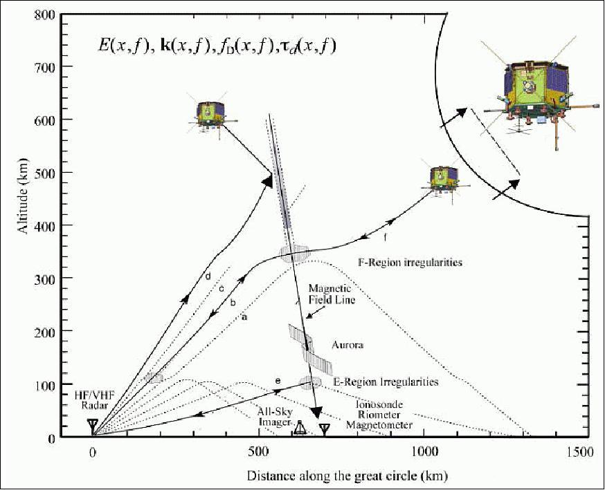
- A number of the planned investigations entail coordinated observations using Canadian and foreign ground facilities, including magnetic and optical observatories, radars, receivers and heaters. An example is the study of trans-ionospheric radio propagation using the RRI on e-POP in conjunction with SuperDARN and CADI (Canadian Advanced Digital Ionosonde) transmitters on the ground. Figure 11 illustrates the geometry in a coordinated radio propagation experiment, in which a high-frequency (HF) radar such as the SuperDARN would irradiate the E and F regions of the high-latitude ionosphere and receive backscatter from density irregularities in both regions. F-region scatter is to be detected on both direct paths such as path "b" and one-and-a-half-hop paths such as path "a", which involves an oblique reflection and a subsequent ground-reflection before backscatter from ionospheric irregularities located beyond the right side of the figure. The intensity of scattered or smoothly propagated radar waves as a function of the position of the onboard receiver will provide information about the angular distribution of the scatter.
- Another example is the study of ionospheric heating in coordination with HF ionospheric heaters such as the HAARP (High Frequency Active Auroral Research Program) facility in Alaska during flights in or near the heater beams, to provide new understanding about the nonlinear interaction of HF waves with E or F-region plasma, using RRI and FAI operating at slew-pointing attitude to remote sense plasma wave and optical emissions resulting from the HF heating.
Preliminary results: Data acquired to date from the 8 e-POP instruments confirm their continuing nominal operations and are currently in different stages of analyses. Figure 12 summarizes the preliminary data from an orbit pass in coordination with the SPEAR radar on November 17, 2013. The bottom panel of this figure shows the propagation of both O- and X-mode waves from the SPEAR radar. The blue and light purple traces depict the O- and X-waves, respectively, at 5 second separation along the CASSIOPE orbit, and show that only the O-mode waves were able to reach the satellite altitude. The middle panel shows the observed amplitude modulation envelope of the resulting RRI antenna voltages. The top panel shows the sinusoidal modulation of the measured voltages on an expanded scale. Detailed analysis will be performed of the precise phase and amplitude of the modulation to investigate the effect of the plasma structures in the ionosphere on the actual wave propagation between the SPEAR radar and the spacecraft. The top panel shows the measured voltage signal on an expanded scale. Detailed analysis will be performed of the precise phase and amplitude of the signal to investigate the effect of the plasma structures in the ionosphere on the actual wave propagation between the SPEAR radar and the spacecraft.
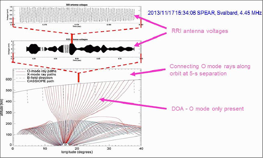
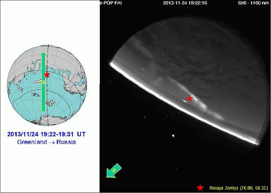
Figure 13 shows an example of NIR (Near Infrared) images of the aurora taken by FAI in its slew imaging mode on November 24, 2013 at 19:22–19:31 UT. At this time, the spacecraft was traversing equator-ward (southward) from Greenland toward Russia (left panel), and the FAI cameras were pointing continuously at the 110-km altitude point (the nominal auroral emission height) above Novaya Zemlya, Russia (76.8°N, 68.3°E; red star in the figure), with the southern horizon toward the bottom left corner of the camera field-of-view (right panel).
An east-west aligned auroral arc was present near (and north of) the Novaya Zemlya Island at this time. The sequence of auroral images from 19:22 to 19:31 UT combine to provide a "tomographic" view of the spatial-temporal variations of the aurora during the 9 minute interval, and enable the reconstruction of the altitude distribution of the auroral emission by tomographic techniques (Ref. 33).
Sensor Complement
ePOP (Enhanced Polar Outflow Probe)
ePOP includes an innovative scientific probe carrying a suite of eight scientific instruments. The ePOP team is led by the University of Calgary (Institute of Space Research) and sponsored by CSA and NSERC (Natural Sciences and Engineering Research Council) of Canada. Other Canadian members of the team are: York University, University of Alberta, Athabasca University, University of Saskatchewan, University of Western Ontario, and the University of New Brunswick. In addition, three research organizations are partners of the project: the Communications Research Centre, Ottawa, JAXA/ISAS (Institute of Space and Astronautical Science), Tokyo, Japan, and the NRL (Naval Research Laboratory), Washington, D.C., USA.
The ePOP mission objective is to investigate atmospheric and plasma flows and related wave-particle interaction and radio wave propagation in the topside ionosphere. Specific objectives are to quantify the micro-scale characteristics of plasma outflow and related micro- and meso-scale plasma processes in the polar ionosphere, explore the occurrence morphology of neural escape in the upper atmosphere, and to study the effects of auroral currents on plasma outflow. The ePOP payload represents Canada's first mission contribution to ILWS (International Living With a Star) initiative. 34) 35) 36) 37) 38)
The ePOP package comprises three interconnected elements:
- a) In-situ observation on a polar orbit. The focus of ePOP is on quantitative in-situ measurements of charged particle distributions, waves, and fields, at the highest possible spatial-temporal resolution, and imaging and tomographic measurements of the large-scale auroral morphology and ionospheric topology.
- b) Coordinated ground-based observations
- c) Related modeling and data assimilation studies.
Instrument | PI (Principal Investigator) | Measurements |
IRM (Imaging Rapid Mass spectrometer) | A.W. Yau (University of Calgary) | 0.5-100 eV ions: composition, energy and 3D angular distributions |
SEI (Suprathermal Electron Imager) | D.J. Knudsen (University of Calgary) | 2-200 eV electrons or ions: energy and 2D angular distributions |
NMS (Neutral Mass and velocity Spectrometer) | H. Hayakawa (JAXA/ISAS) | 0.1-2 km/s, 1-40 AMU neutrals: composition velocity, temperature |
FAI (Fast Auroral Imager) | L.L. Cogger (University of Calgary) | 630 nm, near infrared (650-1100 nm) auroral images |
RRI (Radio Receiver Instrument) | H.G. James (University of Calgary) | ELF-HF waves: electric field E(ϖ) and wave vector k(ϖ) |
MGF (Magnetic Field instrument) | D.D. Wallis (Magnametrics) | Magnetic field perturbation ΔB, field-aligned current j// |
GAP (GPS-based position, Attitude and Profiling) | R.B. Langley (Univ. of New Brunswick) | Apacecraft position and attitude; TEC (Total Electron Content) |
CER (Coherent EM Radio tomography) | P. A. Bernhardt (Naval Research Lab) | TEC and scintillation |
ePOP Instruments
The e-POP mission focuses on in-situ measurements of small-scale plasma, waves, and fields, at the highest possible spatial-temporal resolution in the topside polar ionosphere, and imaging and tomographic measurements of the meso- and large-scale auroral morphology and ionospheric topology.
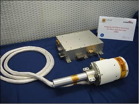
IRM (Imaging and Rapid-scanning Ion Mass Spectrometer)
IRM was designed and developed at the University of Calgary (Peter Amerl and Andrew W. Yau.). The objective is to observe the mass composition and 3-D velocity distributions (energy and angular) of ions in the energy range of 0.1-100 eV and 1-40 amu/q. IRM employs several circuit boards that support a semi-autonomous ion detection and imaging. It consists of a semi-toroidal electrostatic deflection system, a pair of fast-switching time-of-flight electrodes, a hemispherical electrostatic analyzer, a microchannel plate (MCP) detector, and a 64 pixel anode. Its output data rate is driven by the incident ion flux and varies from 0-300 kwords/s.
IRM is an improved version of the Nozomi TPA (Thermal Plasma Analyzer) instrument and its predecessors. The IRM sensor is cylindrical and is deployed on an 8 cm boom. Its entrance aperture has a 360º FOV ( Field of View) perpendicular to the deployment axis and close to 120º FOV along the deployment axis.
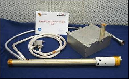
SEI (Suprathermal Electron Imager)
SEI was developed, built and tested at the University of Calgary (PI: David Knudsen). SEI measures the 2-D energy and angular distributions of thermal electrons and soft electrons in the range 1-200 eV/q with particular emphasis on photoelectrons in the 1 to 50 eV range, which are believed to play an important role in the polar wind outflow. The instrument is a derivative of a design by the University of Calgary flown on a sounding rocket campaign. SEI is implemented as a hemispherical electron analyzer with MCP electron amplification producing images on a phosphor screen. The latter images are optically coupled to a frame-transfer CCD located in the electronics module.
The SEI sensor is mounted on a boom of 80 cm in length to place it outside the spacecraft sheath. Its skin bias will be adjustable in its thermal mode to counteract the spacecraft potential and to control the input particle flux. SEI has a FOV of ±15º in elevation and 360º in azimuth. Its entrance aperture plane will be within 15º of the local magnetic field at high latitude.
SEI employs a 256 x 256 pixel CCD detector, which will be optically coupled to the electronics unit and de-coupled from the sensor bias voltages. It uses an MCP to amplify the incident electron azimuth/energy distribution and image it onto a phosphor screen that will be fiber-optically coupled to the CCD sensor. It is capable of operating at an imaging rate of 100 Hz.
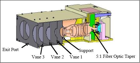
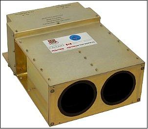
FAI (Fast Auroral Imager)
FAI was developed by a team of experts in partnership from the University of Calgary, Routes AstroEngineering, Burley Scientific, Keo Consultants Inc, and JENOPTIK Optical Systems, Inc. (Leroy Cogger). FAI images the auroral emission in the near infrared (NIR) and visible (VIS) spectral range. The major scientific objectives of the mission are associated with the Earth's high latitude atmosphere and ionosphere. The first thrust is to investigate the outflow of plasma from the polar regions and the related processes of micro-scale ion acceleration and wave-particle interaction, and auroral excitation. The second thrust is the study of 3D ionospheric irregularities using both active and passive radio techniques. The third emphasis is on the escape of neutral particles from high latitudes caused by temperature enhancements as well as by non-thermal processes. 39) 40)
While the spatial resolution capability for most auroral imagers over the past two decades has been of the order of tens of km, the need in the ePOP mission was for an order of magnitude improvement. Likewise, a similar improvement in repetition rate was required. The challenge was met by carefully selecting the spectral elements to image and by taking advantage of the best available technology within the constraint of a very limited budget.
The instrument is a coaligned dual-head CCD imaging camera with detectors for NIR and narrow-band VIS (630 nm), intended to operate only over the polar regions of the orbit. The sensitivity of the cameras was maximized through the choice of a CCD detector and optics module. A thinned, backside-illuminated, high quantum efficiency and low noise CCD was selected, the E2V CCD67 in a 256 x 256 pixel array. The quantum efficiency is 0.8 at 630 nm. With two-stage thermoelectric cooling (TEC) of the AIMO (Asymmetric Inverted Mode Operation) device, the dark current can be kept insignificant for normal instrument operating temperatures. An f/4 telecentric lens system is being used in the optics unit with a 5:1 fiber-optic taper to provide an effective f-number of 0.8. Typically, FAI takes imagery at a rate of about 60 0.1 second exposures per minute with the NIR camera, and 1/2 second exposure per minute with the VIS camera.
Parameter | SV camera (630 nm) | SI camera (NIR) |
Pixel array | 128 x 128 | 256 x 256 |
Projected pixel size | 4.7 km | 2.6 km (from apogee) |
Projected pixel size | 0.4 km | 0.4 km (from perigee) |
Exposure time | 0.5 s | 0.1 s |
Exposure interval | 30 s | 1 s |
Sensitivity (SNR > 3) | 200 rayleigh | 100 rayleigh (557.7 nm equivalent) |
The default operating modes are given in Table 5 for each camera. Calculations of projected pixel size are shown for a satellite orbit apogee of 1500 km and perigee of 300 km. The assumed altitude of the aurora is 220 km for the 630 nm and 110 km for the near infrared emissions. A single pixel of size 26 µm x 26 µm limits the optical resolution of the camera and subtends an angle of about 0.1º.
FAI will aid in the investigation of the relationship between auroral emissions and ion bulk upflow, heating, acceleration, field-aligned currents, and plasma waves. In more specific terms, the FAI was designed to support the investigation of the following:
- The small-scale mechanisms for auroral excitation
- The phenomenon of black aurora and its relation to streaming electrons and ions
- The optical signatures of large-scale convection and their relation to radar measurements
- The connections between aurora and ion energization and bulk upflow.
The FAI imager system will produce 16 bit digital images of the near infrared band at one image per second (again taking advantage of the non-rotating platform on CASSIOPE), and the 630 nm wavelength at two images per minute, giving adequate temporal resolution to investigate the above scientific objectives.
NMS (Neutral Mass and Velocity Spectrometer)
NMS was developed by JAXA/ISAS, Japan (PI: Hajime Hayakawa). NMS measures the density and velocity of neutral atmospheric species using an open-source electron impact ionization chamber and a microchannel plate (MCP) imaging detection subassembly. It employs a planar entrance aperture with a plasma filter to repel low energy charged particles.
NMS is only being operated in the perigee and the near-perigee phase of the orbit (300-400 km) where the atmospheric density is highest. In orbit, neutral particles are rammed into the entrance slit. Internally, NMS employs a high-voltage electron gun to ionize the neutral particles, and an electric-field deflection and focusing system to image the ions onto the MCP detector, which amplifies the ion image by placing then onto a CCD detector of 256 x 256 elements. The CCD data is binned and compressed within the instrument to reduce the data rate.
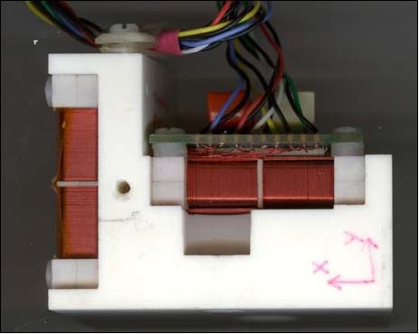
MGF (Magnetic Field Instrument)
MGF was developed by Magnametrics of Ottawa ain partnership with Bennest Enterprises and Narod Geophysics (Lead: Don Wallis). The primary objective of MGF is the characterization of electric currents flowing to and from the high latitude (auroral) ionosphere. The goal of the MGF is the detection of 0.1 µAm-2 currents or stronger at scale sizes of 100 m or larger. This calls for an instrument with resolution of ~0.1 nT and a sample rate of 160 per second. These currents perturb the terrestrial magnetic field causing it to tilt and thereby changing the mapping of in-situ measurements to the auroral phenomena below. This tilt is variable and up to 2º or 3º, and causes the magnetic footprint of the spacecraft to be up to 5 km away from the undisturbed location for every 100 km of altitude above the E-region.
The success of MGF is contingent upon determining the spatial distributions of the field aligned currents in relation to the measurements of other on-board instrumentation. The only means of making this determination is through the perturbations of the geomagnetic field associated with these currents.
For this reason a specially designed fluxgate vector magnetometer is employed. MGF employs dual sensors on a 80 cm carbon fiber boom, at two separations to estimate and correct for the spacecraft influences. The instrument measures the vector magnetic field (in 3 digital output channels) with a precision of 21 bit, a resolution of 0.0625 nT and a dynamic range of ±65,536 nT. The sampling rate is 160 Hz. The MGF relies on a unique ranging design that was previously adopted successfully in the design of the CANOPUS magnetometers. 41) 42)
RRI (Radio Receiver Instrument)
RRI was designed and developed at COM DEV,Ottawa, Canada under the direction of PI Gordon James from CRC (Communications Research Centre). The instrument measures radio waves in the ULF and HF frequency range (up to 18 MHz). RRI is a four-channel ULF/HF digital radio receiver is operating in burst mode when it is in the beams of cooperating HF ground radars such as CADI (Canadian Advanced Digital Ionosondes) and SuperDARN (Super Dual Auroral Radar Network), an international mostly ground-based distributed radar network for studying the Earth's upper atmosphere, ionosphere, and connection into space. The burst mode lasts during the acquisition phase of the orbital overflight (several minutes) of the ground radars. 43) 44) 45) 46) 47)
The RRI is being fed by four 3 m monopoles with preamplifiers. From below 100 Hz to about 3 MHz, the RRI measures the electric fields of spontaneous waves. Between about 10 kHz and 18 MHz, the receiver measures the electric fields of waves created by ground transmitters, such as ionosondes, HF radars and ionospheric heaters. The scientific objectives of the RRI program are to improve understanding in the following areas:
- The morphology and dynamics of density structure in the ionosphere
- The generation of spontaneous radio emissions created by auroral processes
- The nonlinear plasma physics of the HF-modified ionosphere
- The physics and metrology of radiowave scattering, diffraction and refraction.
The RRI measures and record various parameters associated with RF wave electric fields E incident upon the spacecraft. The magnitudes of E in the case of discrete modulated CW signals emitted by artificial sources on the ground below require to be accompanied by information about the wave polarization or DOA (Direction of Arrival) of the incident waves. The detection of the Doppler shift of artificial signal carrier frequencies constitutes an independent tool for checking the direction of propagation of waves. The absolute time stamp (to an accuracy of ±8 µs) permits the determination of the absolute signal delay time of waves from the ground.
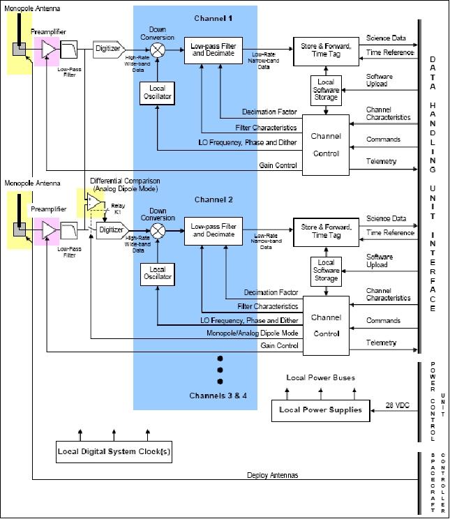
The RRI instrument design features a dynamic range of 120 dB above an input threshold of 0.3 µV. This total range is achieved by dividing it into three overlapping preamplifier gain settings, each of 72 dB. Bandwidths up to a maximum of 30 kHz are available in each of the four receiver channels. Both the amplitude and relative phase of an incoming electric field can be measured. After suitable amplification, the signals are digitized and then processed by a digital down converter and decimating low-pass filter. The resultant digital data are time-tagged to an accuracy < ±8 µs. The system has four identical signal processing channels, of which two are shown in Figure 22. Each channel is tied to a single monopole antenna.
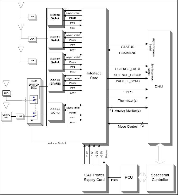
GAP (GPS Attitude and Positioning Experiment)
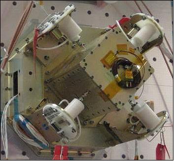
GAP is of the UNB (University of New Brunswick). The objective is to measure S/C velocity and attitude as well as TEC (Total Electron Content) of the ionosphere. The relative phase delay of signals in both the L1 and L2 bands from a GPS satellite occulted by the limb ionosphere provide large-scale (1000's of km) information on how the total electron content responds to magnetospheric perturbations. GAP consists of two components: 48) 49)
- GAP-A: Three single-frequency (L1) GPS receivers and four patch antennas. This package is being used to provide an accurate absolute time reference, spacecraft 3-D attitude, and post-processed spacecraft position and velocity.
- GAP-O: The objective is to provide ionospheric tomography observations. GAP-O consists of a dual-frequency (L1/L2) GPS receiver with a phase data sampling rate of > 10 Hz, sufficient for tomographic analysis.
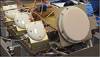
The four GAP-A patch antennas are mounted on opposite sides of the S/C in the zenith direction to minimize multipath reflections from the S/C structure and to maximize the baseline between the antennas - to improve the accuracy of the 3-D attitude.
For GAP-O, the helical antenna is being placed on the X side of the S/C. Phase measurements are acquired for several minutes (5-7) per occultation from a GPS satellite in occultation using the dual-frequency receiver.
GAP distributes also its time signals to certain ePOP instruments for precise time stamping of science data via the DHU (Data Handling Unit) of ePOP.
GAP employs five differential Global Positioning System receivers and associated antenna complement to provide the e-POP payload with high-resolution spatial positioning information, flight-path velocity determination, and real-time, high-stability timing. In addition, by measuring the arrival times of the various GPS signal wave fronts at each antenna against a very stable time base, the relative range between antennas can be determined, yielding real-time spacecraft attitude determination. One of the GAP antennas is mounted on the anti-ram side of the spacecraft and dedicated to ionospheric radio occultation measurements in which the relative phase delay of the measured L1 and L2 signals (at frequencies of 1.57542 GHz and 1.2276 GHz, respectively) from different satellites of the GPS constellation will be used to determine the electron density profile of the ionosphere using tomographic techniques. The other four antennas are mounted on the anti-nadir face of the spacecraft, with bore-sights normal to the spacecraft surface, and are used primarily for the timing, position, and velocity measurements.
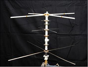
CER (Coherent Electromagnetic Radiation)
CER was developed at NRL (Naval Research Laboratory) in Washington, D.C. (Paul Bernhardt). The objective is to determine ionospheric total electron density (TEC) by using a three-frequency beacon; cooperative ionospheric observations with fixed ground receivers. The instrument is of CERTO (Coherent Electromagnetic Radio Tomography Instrument) heritage flown on ARGOS of DoD (launch Feb. 23, 1999) and on PICOSat (launch Sept. 30, 2001) of DoD.
CER consists of a tri-frequency beacon and a three-frequency, circular polarized antenna on a 68.6 cm boom. CER provides a global ionospheric map to aid the prediction of radio-wave scattering. CER transmits three beacon signals near 150, 400, and 1066 MHz (VHF/UHF bands), for reception by a network of ground receiving stations located around the globe. Data are collected from these receiving stations and analyzed, producing 2-D ionospheric density maps.
CX (Cascade Experimental), Pilot Phase of a New Information Delivery Service
CX is an advanced satellite communication demonstration payload with twofold mission objectives:
- a) it must develop and demonstrate the key Cascade enabling technologies
- b) it must demonstrate the feasibility of the unique very large file end-to-end transfer method, envisioned in support of a future Cascade digital courier service.
Key enabling Cascade technologies to be demonstrated include: Ka-band RF transmit and receive chains, 350 Mbit/s digital space-qualified modulators and demodulators, and high-capacity, low-power and low-mass onboard bulk data storage (1+ Tbit of onboard memory). CASCADE uses the unique GigaPackage ExpressTM store-and-forward technology developed by MDA (pickup and delivery of huge data packages: 50-500 GByte/day).
The CX users are responsible for proof of the Cascade technologies. The CX users request data delivery service via the CX ground terminal. In turn, they provide user data over a high-speed line to the CX ground terminal for uplink service to the spacecraft. 50)
The CX Cascade system provides:
- Daily accessibility to any point on the globe excluding the polar regions
- High bandwidth data links
- Large capacity storage onboard the spacecraft
- Service on a regular and reliable basis
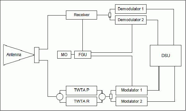
The CX payload provides two-way data communications capability to a GT (Ground Terminal). The payload consists of two major parts, the RF/Digital Subsystem and the Data Storage Unit. The payload is operated in a half-duplex mode, either transmitting or receiving, but not both simultaneously. Generally during a single contact with a ground station the payload will transmit or it will receive, however, nothing precludes the payload from switching between transmit and receive during a contact. In fact for CASSIOPE, this capability was demonstrated (Ref. 31).
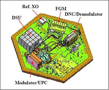
The RF/Digital Subsystem for the CX payload was built up to demonstrate two channels of the CASCADE system. Common to both the uplink and downlink chains are the body mounted horn antenna, the MO (Master Oscillator) and the FGU (Frequency Generation Unit). The uplink chain also has a receiver as well as a two channel Demodulator, while the downlink chain has a primary and redundant TWTA (Travelling Wave Tube Amplifier) and a two channel Modulator. The two channels on the CX payload are RHCP and separated in frequency. Each channel operates at 350 Mbit/s.
A high capacity DSU (Data Storage Unit) is key to the store and forward mode of operation for CASCADE. The DSU has 1 Tb of storage broken over four storage sub-units. Two of these are dedicated to CX data storage and the others are dedicated to ePOP. The DSU has a data link to the ePOP Payload to allow the storage of science data on the DSU for Ka-band downlink.
Early in the CASSIOPE program, an opportunity to increase the amount of science downlinked was identified. By adding a data link between the ePOP Payload and the DSU, ePOP science could be downlinked on the CASCADE Ka-band link as well as the S-band link. Given the difference in the data rates (4 Mbit/s for S-band versus 350 Mbit/s for Ka-band), this was seen as a way to potentially increase the science yield by over an order of magnitude.
Associated with the payload is the CX ground terminal. The CX ground terminal provides the terrestrial end of the high rate Ka-band link and allows data to be moved onto or off of the system. The terminal is both transmit and receive capable on a half-duplex basis. For convenience of operations, the CX ground terminal has been co-located with the Mission Operations team in Calgary, Alberta, Canada.
Over the years, the CX design has evolved into a new system called PCPMU (Payload Controller, Processor and Memory Unit).
PCPMU (Payload Controller, Processor and Memory Unit)
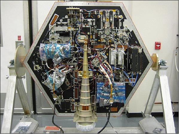
The innovative and compact PCPMU design challenges the conventional approach to PE (Payload Electronics) by incorporating a modular architecture utilizing highly integrated, multi-purpose components (based on reconfigurable, state-of-the-art FPGA technology) and standardized interfaces. This approach introduces a scalable, multi-mission capability providing for a rapid, low-cost PE assembly, test and integration that results in a reduction in complexity, mass and volume, and a corresponding increase in reliability. 52)
The PCPMU architecture is based on the use of DMFC (Digital Multi-Function Card), a software reconfigurable digital signal processing card that can be programmed to perform a variety of mission specific functions.
The PCPMU comprises two main sections: a Controller/Processor section that is mission specific, and a DSU (Data Storage Unit) section that is common for all configurations.
• The Controller/Processor section, based on the DMFC, can be configured to provide a variety of core functions: overall payload control and interface to bus and payload instrument, DC power conditioning, echo or replica data processing for SAR (Synthetic Aperture Radar), or image data compression for optical missions, and on-board data processing (modulation and demodulation) for store-and-forward communication missions.
• The DSU (Data Storage Unit) is a highly scalable unit, also based on DMFC that provides control and data management function, and integrates at least two memory cards, each with a capacity of 1 Tbit at EOL (End-of-Life). Additional memory boards can be added to achieve capacity of up to 8 Tbit at EOL. This storage unit offers significantly reduced power consumption compared to the traditional solid state mass memory solutions as the unit uses non-volatile memory and can be switched off completely when not in use.
The Communication PCPMU architecture is developed to provide on-board data processing and storage for the CASCADE mission – a fleet of low-cost LEO small satellites for high bandwidth, store-and-forward communications. CASCADE enables the transfer of large digital data files (10s to 100s of GBytes) from/to anywhere in the world, including polar areas, within hours. It uses Ka-band links at aggregate data rate of up to 1.4 Gbit/s (QPSK modulation), or up to 2.1 Gbit/s using higher order modulations.
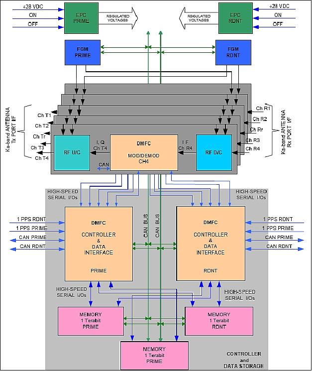
The Communications PCPMU consists of a PU (Processing Unit) and a DSU (Data Storage Unit). The PU comprises five identical, independent MDMs (Modulator/Demodulator) assemblies, and a pair of (prime and redundant) FGMs (Frequency Generator Modules) and EPCs (Electric Power Control) cards.
The communication DSU functionality is similar to the optical DSU. The CDI (Controller and Data Interface) card, besides data routing, formatting, and file management, also performs payload operational control, interfaces with the spacecraft bus over the TT&C interface, and acts as a master on the internal CAN (Controller Area Network) bus. The communication PCPMU architecture is presented in Figure 30.
The CASSIOPE mission will carry store-and-forward communication payload enabling 0.7 Tbit/s data transfer rate and will have data storage capacity of 1 Tbit. Replacing the conventional PE (Payload Electronics) with the PCPMU configuration will bring mass and peak power consumption down by 64% and 58%, respectively.
The PCPMU has a mass of 21 kg and a peak power consumption of 135 W (64 W average).
The PCPMU architecture and the design methodology focuses on creating reconfigurable Payload Electronics (PE) based on card/module reuse and utilization of reconfigurable cards that minimizes non-recurring engineering at the payload and overall mission level.
The PCPMU design utilizes a combination of space qualified and screened OTS (Off-The-Shelf) parts. A significant contributor to the performance and low price points of the PCPMU is the application of a flight proven, NASA approved process that enables cost effective application of OTS parts for space.
Ground Segment
The ground segment consists of MCC (Mission Control center), the CX ground terminal, the CX SCC (Service Control Center) and GSE (Ground Support Equipment). In addition, there is the SOC (Science Operations Center) in support of the ePOP payload. SOC will be operated at the University of Calgary. The SOC schedules and coordinates the ePOP instrument data collection. SOC receives the ePOP data via S-band downlink over Mission Control and over Ka-band via the CX ground terminal.
References
1) Andrew Yau, Gordon James, Gregory Enno, Robert Hum, Peter Duggan, Mark Senez, Ziad Ali, Gilles Brassard, Berthier Desjardins, Luc Dubé, Richard Giroux, Dave Beattie, Ian Walkty, "Multidimensional Challenges and Benefits of the CASSIOPE Mission," Proceedings of the IAA Symposium on Small Satellite Systems and Services (4S), Rhodes, Greece, May 26-30, 2008, ESA SP-660, August 2008
2) A. W. Yau, E. P. King, R. Hum, H. G: James, W. Ressl, S. Oldham, A. Dubeau, Z. Ali, W. Liu, R. Shelly, "The Canadian Enhanced Polar Outflow Probe on the Canadian CASSIOPE SmallSat," Proceedings of IAC 2004, Vancouver, Canada, Oct. 4-8, 2004, IAC-04-IAA.4.11.2.05
3) G. B. Giffin, W. Ressl, A. W. Yau, E. P. King, "CASSIOPE: A Canadian Smallsat-Based Space Science and Advanced Satcom Demonstration Mission," Proceedings of AIAA/USU Conference on Small Satellites, Logan, UT, Aug. 9-12,2004, SSC04-VI-5
4) G. Giffin, K. Magnussen, M. Wlodyka, J. Bravman, "CASCADE: A SmallSat System Providing Global, High Quality Movement of Very Large Dat Files," Proceedings of IAC 2004, Vancouver, Canada, Oct. 4-8, 2004, IAC-04-M.4.06
5) http://www.asc-csa.gc.ca/eng/satellites/cassiope.asp
6) J. Bates, "Canada Funds Small Satellite Platform Demonstration," Space News, Feb. 16, 2004, p. 8
7) A. W. Yau, H. G. James, "The Canadian CASSIOPE Enhanced Polar Outflow Probe (e-POP) for High-Resolution Observations of SpaceWeather Processes," 58th IAC (International Astronautical Congress), International Space Expo, Hyderabad, India, Sept. 24-28, 2007, IAC-07- B.2.06
8) "CASSIOPE/e-POP Fact Sheet," University of Calgary, URL: http://epop.phys.ucalgary.ca/quickfacts.html
9) S. Page, R. Harris, I. Walkty, D. Beattie, H. Dahl, "The Development of the MAC-200 Small Satellite Bus for the Canadian Space Agency," Proceedings of the 13th Canadian Astronautics Conference, ASTRO 2006, Montreal, QC, Canada, organized by CASI (Canadian Astronautics and Space Institute), April 25-27, 2006
10) A. Denis, S. Page, I. Walkty, "The Evolution of a SciSat-1 Spacecraft to Provide a Generic Small Satellite Bus for the Canadian Space Agency," Proceedings of IAC 2004, Vancouver, Canada, Oct. 4-8, 2004, IAC-04-IAA.4.11.2
11) W. Peruzzini, G. Brassard, "Canadian Multi-Mission Small and Micro Satellite Buses," Proceedings of IAC 2004, Vancouver, Canada, Oct. 4-8, 2004, IAC-04-IAA.4.11.6.02
12) Y. Soucy, A. Woronko, P. Tremblay, M. O'Grady, "Force limited vibration testing applied to the CASSIOPE spacecraft," Proceedings of ASTRO 2010, 15th CASI (Canadian Aeronautics and Space Institute) Conference, Toronto, Canada, May 4-6, 2010
13) "Successful Launch of CASSIOPE: Hybrid Satellite Mission Carrying Science and Telecommunications Payloads," CSA, Sept. 29, 2013, URL: http://www.asc-csa.gc.ca/eng/media/news_releases/2013/0929.asp
14) Patrick Blau, "SpaceX successfully Launches Upgraded Falcon 9 on 1st Demonstration Flight," Spaceflight 101, Sept. 29, 2013, URL: http://www.spaceflight101.com/falcon-9-v11-cassiope-launch-updates.html
15) Marc Boucher, "Canada's CASSIOPE Satellite Nearing Liftoff," SpaceRef, June 26, 2012, URL: http://spaceref.ca/missions-and-programs/
canadian-space-agency/canadas-cassiope-satellite-nearing-liftoff.html
16) Emily Underwood, "How Heavy Oxygen Ions Escape Earth's Gravity — A new study reveals that low-frequency electromagnetic waves accompany intense heating events at low altitudes," EOS 99, 5 April 2018, URL: https://eos.org/research-spotlights/how-heavy-oxygen-ions-escape-earths-gravity
17) Yangyang Shen, David J. Knudsen, Jonathan K. Burchill, Andrew D. Howarth, Andrew W. Yau, David M. Miles, H. Gordon James, Gareth W. Perry, Leroy Cogger, "Low-altitude ion heating, downflowing ions, and BBELF waves in the return current region," Journal of Geophysical Research: Space Physics, First published: 8 March 2018, https://doi.org/10.1002/2017JA024955
18) "Swarm trio becomes a quartet," ESA, 22 Feb. 2018, URL: http://m.esa.int/Our_Activities/Observing_the
_Earth/Swarm/Swarm_trio_becomes_a_quartet
19) D. M. Miles, I. R. Mann, I. P. Pakhotin, J. K. Burchill, A.D. Howarth, D. J. Knudsen, R. L. Lysak, D. D. Wallis, L. L. Cogger, A. W. Wau, "Alfvénic Dynamics and Fine Structuring of Discrete Auroral Arcs: Swarm and e-POP Observations," Geophysical Research Letters, Volume 45, Issue 2, 28 January 2018, pp: 545–555, https://doi.org/10.1002/2017GL076051
20) Andrew W. Yau, R. Floberghagen, Leroy L. Cogger, EelcoN. Doornbos, Gregory A. Enno, Gauthier Hulot, H. Gordon James, David J. Knudsen, Richard B. Langley, David M. Miles, Nils Olsen, Claudia Stolle, "New Synergistic Opportunities for Magnetosphere-Ionosphere-Thermosphere Coupling Investigations Using Swarm and CASSIOPE e-POP," Fourth Swarm Science Meeting & Geodetic Missions Workshop, March 20-24, 2017, Banff, Canada, Note: The presentation of this paper was provided by Andrew W. Yau.
21) Morten Garly Andersen, "Solar storms trigger surprising phenomena close to Earth," DTU (Technical University of Denmark), March 1, 2017, URL: http://www.dtu.dk/english/news/2017/03/solar-storms-trigger-
surprising-phenomena-close-to-earth?id=8ad59676-0821-46a6-a868-28ac6c429f0a
22) Tibor Durgonis, Attila Komjathy, OlgaVerkhoglyagova, Esayas B. Shume, Hans-Henrik Benzon, Anthony J. Mannucci, Mark D. Butala, Per Hoeg, Richard B. Langley, "Multiinstrument observations of a geomagnetic storm and its effects on the Arctic ionosphere: A case study of the 19 February 2014 storm," Radio Science, Volume 52, Issue 1, January 2017, pp: 146–165, DOI: 10.1002/2016RS006106, URL of abstract: http://onlinelibrary.wiley.com/doi/10.1002/2016RS006106/full
23) G. W, Perry, H. G. James, R. G. Gillies, A.Howarth, G. C. Hussey, K. A. McWilliams, A. White, A. W. Yau, "First results of HF radio science with e-POP RRI and SuperDARN," Radio Science, Volume 52, Issue 1, pp: 78–93, January 2017, URL of abstract: http://onlinelibrary.wiley.com/doi/10.1002/2016RS
006142/abstract?campaign=wolacceptedarticle
24) "CASSIOPE Celebrates Three Years in Space," University of Calgary, Sept. 29, 2016, URL: http://epop.phys.ucalgary.ca/cassiope-celebrates-three-years-in-space/
25) Andrew W. Yau, H. Gordon James, Gregory A. Enno, Carlos Alonso, "Scientific results from the enhanced Polar Outflow Probe (e-POP) in the Canadian CASSIOPE small satellite mission," Proceedings of the 4S (Small Satellites, System & Services) Symposium, Valletta, Malta, May 30-June 3, 2016, URL: http://congrexprojects.com/docs/default-source/16a02
_docs/4s2016_final_proceedings.zip?sfvrsn=2
26) Information provided by Andrew W. Yau, Mission Scientist and Project Leader of e-POP, University of Calgary, Canada.
27) "e-POP (Enhanced Polar Outflow Probe)," accessed on Feb. 2, 2016, URL: http://epop.phys.ucalgary.ca/
28) "CASSIOPE: Observing Space Weather with a Hybrid Satellite," CSA, March 25, 2015, URL: http://www.asc-csa.gc.ca/eng/satellites/cassiope.asp
29) Elizabeth Landau, "Study of atmospheric 'froth' may help GPS communications," NASA/JPL, Feb. 26, 2015, URL: http://www.jpl.nasa.gov/news/news.php?feature=4493
30) E. B. Shume1, A. Komjathy, R. B. Langley, O. Verkhoglyadova, M. D. Butala1, A. J. Mannucci, "Intermediate-scale plasma irregularities in the polar ionosphere inferred from GPS radio occultation," Geophysical Research Letters, Feb. 9, 2015, DOI: 10.1002/2014GL062558
31) Mark Senez, Jeff Hemingway, Bruce Entus, A.W. Yau, G.A Enno, "Early Results of the CASCADE Technology Demonstration Payload on CASCADE," Proceedings of the AIAA/USU Conference on Small Satellites, Logan, Utah, USA, August 2-7, 2014, paper: SSC14-XII-5, URL http://digitalcommons.usu.edu/cgi/viewcontent.cgi?article=3076&context=smallsat
32) A.W. Yau, Z. Ali, C. Alonso, C. Casgrain, G.A. Enno, B. Entus, M. Grigorian, J. Hemingway, A. Howarth, R.H. Hum, H.G. James, P. Langlois, M. Senez, A. White, "The Canadian CASSIOPE Small Satellite Mission: the Enhanced Polar Outflow Probe and CASCADE Technology Demonstration Payload," Proceedings of the 65th International Astronautical Congress (IAC 2014), Toronto, Canada, Sept. 29-Oct. 3, 2014, paper: IAC-14.B4.2.2
33) A. W. Yau, Z. Ali, C. Alonso, C. Casgrain, L. L. Cogger, G. A. Enno, B. Entus, M. Grigorian, J. Hemingway, A. Howarth, R. H. Hum, H. G. James, P. Langlois, M. Senez, A. White, "The Canadian CASSIOPE Small Satellite Mission: the Enhanced Polar Outflow Probe and CASCADE Technology Demonstration Payloads," Proceedings of the 4S (Small Satellites Systems and Services) Symposium, Port Petro, Majorca Island, Spain, May 26-30, 2014
34) "e-POP - Enhanced Polar Outflow Probe," URL: http://epop.phys.ucalgary.ca/payload.html
35) http://mertensiana.phys.ucalgary.ca/cassiope.htm
36) H. G. James, P. A. Bernhardt, R. B. Langley, C. L. Siefring, A. W. Yau, "Radio-science experiments with the Enhanced Polar Outflow Probe satellite payload using its RRI, GAP and CERTO instruments," URSI GA2005 New Delhi, India, Oct. 23-29, 2005, URL: https://www.ursi.org/proceedings/procGA05/pdf/G04.9(01742).pdf
37) M. Nejad Ensan, D. G. Zimcik, "Response of the Enhanced Polar Outflow Probe (ePOP) Instrument Under Shock Loading," Proceedings of the 11th International LS-DYNA Users Conference, Detroit, MI, USA, June 6-8,, 2010, URL: http://www.dynalook.com/international-conf-2010/Simulation-5-4.pdf
38) A.W. Yau, C. Alonso, G.A. Enno, M. Grigorian, R.H. Hum, H.G. James, R. Giroux, P. Langlois, B. Poller, M. Senez, "The Canadian CASSIOPE Small Satellite Mission: The Enhanced Polar Outflow Probe and CASCADE Technology Demonstration Payloads," Proceedings of the 4S (Small Satellites Systems and Services) Symposium, Portoroz, Slovenia, June 4-8, 2012
39) L. Cogger, S. Murphree, T. Trondsen, A. Yau, D. Asquin, B. Gordon, P. Marchand, D. Ng, G. Burley, M. Lessard, "The Fast Auroral Imager Experiment to Investigate the Dynamics of Nighttime Optical Aurora as part of the CASSIOPE/ePOP Mission," Proceedings of the 13th Canadian Astronautics Conference, ASTRO 2006, Montreal, QC, Canada, organized by CASI (Canadian Astronautics and Space Institute), April 25-27, 2006
40) http://mertensiana.phys.ucalgary.ca/FAI.html
41) D. D. Wallis, B. B. Narod, J. R. Bennest, "The ePOP / CASSIOPE Magnetic Field Instrument," Proceedings of the 13th Canadian Astronautics Conference, ASTRO 2006, Montreal, QC, Canada, organized by CASI (Canadian Astronautics and Space Institute), April 25-27, 2006
42) http://mertensiana.phys.ucalgary.ca/MGF.html
43) H. G. James, W. H. H. J. Lunscher, "The Radio Receiver Instrument on CASSIOPE/ePOP," Proceedings of the 13th Canadian Astronautics Conference, ASTRO 2006, Montreal, QC, Canada, organized by CASI (Canadian Astronautics and Space Institute), April 25-27, 2006
44) H. G. James, C. L. Siefring. E. P. King, "The Radio Receiver Instrument on the e-POP small satellite", Proceedings of the 12th Conference on Astronautics, Astro2002, CASI, Ottawa, Canada, Nov. 12-14, 2002.
45) G. C. Hussey, H. G. James, G. J. Sofko, "Radar Observations of the Ionosphere from Space: A Preliminary Instrument Proposal," Proceedings of the 13th Canadian Astronautics Conference, ASTRO 2006, Montreal, QC, Canada, organized by CASI (Canadian Astronautics and Space Institute), April 25-27, 2006
46) http://mertensiana.phys.ucalgary.ca/RRI.html
47) http://mertensiana.phys.ucalgary.ca/info/RRI-1-pager.pdf
48) http://mertensiana.phys.ucalgary.ca/GAP.html
49) Don Kim, Richard B. Langley, "GPS RTK-Based Attitude Determination for the e-POP Platform onboard the Canadian CASSIOPE Spacecraft in Low Earth Orbit," TimeNav'07 (ENC GNSS 2007), 29 May - 1 June 2007, Geneva, Switzerland, URL: http://gauss.gge.unb.ca/papers.pdf/encgnss2007.kim.pdf
50) B. Gordon, L. Piché, J. Bourdeau, S. Bazley, K. Magnussen, G. Giffin, L. Laba, J. Tulip, "A High Speed, High Capacity, Data Storage Unit based on Digital FLASH Technology for Next Generation Space Missions including CASSIOPE/CASCADE," Proceedings of the 13th Canadian Astronautics Conference, ASTRO 2006, Montreal, QC, Canada, organized by CASI (Canadian Astronautics and Space Institute), April 25-27, 2006
51) http://epop.phys.ucalgary.ca/cascade.html
52) Sasa T. Trajkovic, George Tyc, Kenneth V. James, Daniel J. Schulten, Peter Allan, Ed Ahad, Richard Allen, Simon Ladouceur, Martin Cote, "PCPMU: A Modular, Multi-Use Payload Electronics Architecture for Affordable, Responsive Missions," 7th Responsive Space Conference, April 27–30, 2009, Los Angeles, CA, USA, AIAA-RS7-2009-3006, presentation URL: https://web.archive.org/web/20150607214825/http://www.responsivespace.com/Papers/RS7/SESSIONS/Session%20III/3006_Trajkovic/3006C.pdf
The information compiled and edited in this article was provided by Herbert J. Kramer from his documentation of: "Observation of the Earth and Its Environment: Survey of Missions and Sensors" (Springer Verlag) as well as many other sources after the publication of the 4th edition in 2002. - Comments and corrections to this article are always welcome for further updates (eoportal@symbios.space).
Spacecraft Launch Mission Status Sensor Complement e-POP Instruments
Ground Segment References Back to Top