BRICSat-P (Ballistic Reinforced Communication Satellite-Prototype)
EO
Mission complete
UNSA
Quick facts
Overview
| Mission type | EO |
| Agency | UNSA |
| Mission status | Mission complete |
| Launch date | 20 May 2015 |
| End of life date | 31 Dec 2018 |
| CEOS EO Handbook | See BRICSat-P (Ballistic Reinforced Communication Satellite-Prototype) summary |
BRICSat-P (Ballistic Reinforced Communication Satellite-Prototype)
Spacecraft Launch Mission Status Sensor Complement References
BRICSat-P is a collaborative 1.5U CubeSat mission of USNA (United States Naval Academy), Annapolis, MD, and the GWU (George Washington University), Washington DC, USA. The overall objective is to demonstrate on-orbit operation of an electric propulsion system. A four thruster head system will be placed on one side of the spacecraft around the center of gravity and will de-tumble the satellite from its initial expulsion, demonstrate rotational control about two axes, and perform a delta-v end-of-life scenario. Orbital analyses performed indicate that the four thruster-head system is able to fit in a 1.5U CubeSat with low power consumption such that other subsystems such as communication systems can perform normally. Dynamics analysis has been performed in MATLAB Simulink and STK that shows the thrusters can successfully perform the attitude control maneuvers. 1) 2) 3) 4)
Spacecraft
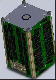
BRICSat-P s an experimental CubeSat mission operated by the USNA Lab to demonstrate the on-orbit operation of µCAT (Micro-Cathode Arc Thruster) provided by GWU. The satellite also carries on amateur communications payload, APRS (Automatic Packet Reporting System), to be accessed by radio operators around the world. The satellite is 1.5U in size with a mass of 1.9 kg.
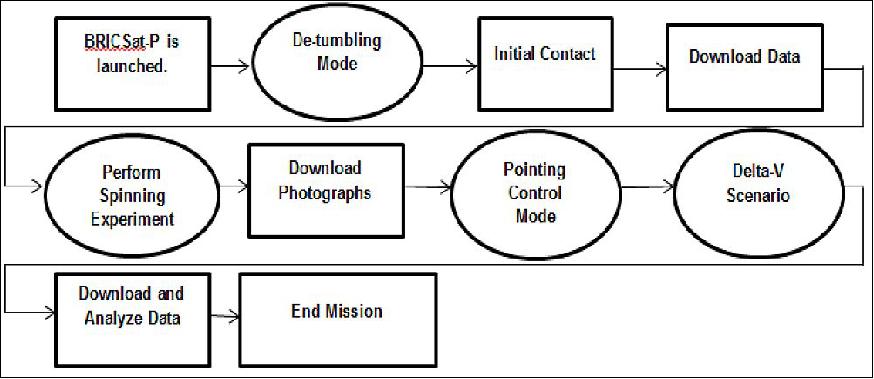
BRICSat-P is the first flight test for the µCAT system. The mission will conduct three primary flight experiments:
1) Detumble: BRICSat-P will use its thrusters to detumble, demonstrating the thrusters ability to act as an attitude control system.
2) Rotation: The rotational experiment uses the thrusters to rotate the spacecraft up to 6 rpm, which will evaluate the thrusters performance against known quantities.
3) Delta V: BRICSat-P will use its thrusters to change its orbit.
The results of these experiments will affect further development of the BRICSat product line.
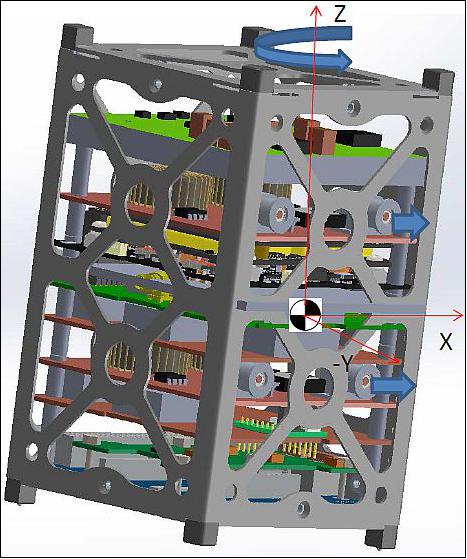
BRICSat-P Design
• Place four thruster heads around center of mass
• Permanent magnet to stabilize CubeSat (gyro and magnetometer used for measurements)
• Use thrusters for attitude and rate control
- Meets all of mission objectives
- Fully characterize thruster system
• Thruster configuration chosen: X-wing (all thrusters on same face)
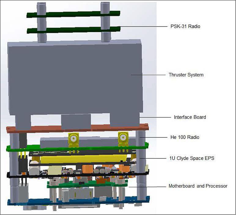
The subsystems of BRICSat-P consist of the EPS (Electrical Power Subsystem), experimental band monitor, command receiver and transmitter with OBC (On Board Computer). The EPS consists of 6 solar cells, so that each is placed on one side of the cube. Each cell is connected to one of five rechargeable NiMh batteries with 1800 mAh capacity through an isolating diode, while the top and bottom cells charge the same battery cell. This design ensures satellite operation even in the case if some solar panel or battery cell fails to open, or to the short state. 5)
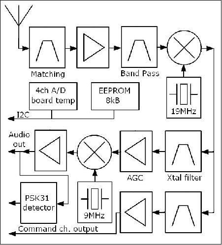
PSK31 transponder of Brno University Czech Republic: The receiver is designed as double conversion superheterodyne with input in 28 MHz band and audio output of demodulated signal with 2.5 kHz bandwidth. Typical received signal is multiple PSK31 (Phase Shift Keying 31 Baud) transmissions, which are spread in 2.5 kHz band around 28.120 MHz. The receiver consists of antenna matching circuit, input filter, preamplifier and band filter, followed by the mixer. The signal chain continues with quartz band pass filter, variable gain amplifier and second mixer for conversion to audio band. The receiver includes automatic gain control with 60 dB dynamic range, detection of BPSK31 modulation in the received channel and a command channel output as can be seen in Figure 4. The TX board also includes a four channel A/D converter for the battery cells voltage and the receiver board temperature monitoring. An 8 kB EEPROM memory is used for telemetry data storage. Both chips are connected via an I2C bus with the controller. The whole receiver is supplied via a 5 V low drop stabilizer, however the full functionality of the device is tested down to 3.5 V. The realized flight prototype can be seen in Figure 4.
Launch
The BRICSat-P nanosatellite was launched on May 20, 2015 (15:05:00 UTC) as a secondary payload on an Atlas-5 -501 EELV (Evolved Expendable Launch Vehicle) of ULA from the Cape Canaveral Air Force Station (SLC-41) in Florida. The primary mission was the AFSPC-5 (Air Force Space Command -5) mission -referring to the Boeing built X-37B spaceplane of the USAF into LEO. The X-37B is an unmanned reusable mini shuttle, also known as the Orbital Test Vehicle (OTV) and is flying on the OTV-4 mission. It launches vertically like a satellite but lands horizontally like an airplane. The X-37B mission is testing an electric Hall Effect thruster in its small payload bay, which will be used on future US Air Force satellites. 6) 7)
This Atlas-5 mission also includes the ABC (Aft Bulkhead Carrier) carrying the NRO's (National Reconnaissance Office's) Ultra Lightweight Technology and Research Auxiliary Satellite (ULTRASat).
Secondary Payloads
The Atlas V sent the U.S. Air Force's X-37B space plane on its fourth mission, which also is carrying NASA's METIS (Materials Exposure and Technology Innovation in Space) investigation that will expose about 100 different materials samples to the space environment for more than 200 days. 8) 9) 10)
ELaNa-XI CubeSats: NASA will enable the launch of a small research satellite, or CubeSat, for The Planetary Society in Pasadena, California, as part of the eleventh installment of the Educational Launch of Nanosatellite (ELaNa) mission. The LightSail CubeSat is included as part of an auxiliary payload of 10 CubeSats on the upper stage of the Atlas V rocket that was launched on the U.S. Air Force X-37B space plane's fourth mission. 11)
The upper stage of the Atlas-5 included the National Reconnaissance Office's third auxiliary mission to launch CubeSats. The ULTRASat (Ultra Lightweight Technology and Research Auxiliary Satellite) carried 10 CubeSats from five organizations. It was made possible through agreements between NASA, the Air Force's Space and Missile Systems Center and the NRO (National Reconnaissance Office) to work together on CubeSat integration and launch opportunities. 12)
• LightSail-A, a 3U CubeSat of The Planetary Society, Pasadena, CA.
• USS (Unix Space Server) Langley, a 3U CubeSat of the USNA (U.S. Naval Academy) Annapolis, MD. USS Langley is a proof-of-concept mission for providing global Internet access via a nanosatellite constellation. The USS Langley satellite uses a 3U CubeSat bus procured from Pumpkin Inc. under the Colony-1 program of the National Reconnaissance Office.
• BRICSat-P (Ballistic Reinforced Communication Satellite-Propulsion Test Unit), a CubeSat of USNA /George Washington. BRICSat-P is a collaborative 1.5U CubeSat mission of USNA, Annapolis, MD, and the George Washington University, Washington DC, USA. The primary objective is to demonstrate on-orbit operation of an electric propulsion system. 13) 14)
• ParkinsonSat, two 1.5U CubeSats of the USNA (United States Naval Academy). PSat (short for ParkinsonSat) employs a two- way communications transponder for relaying remote telemetry, sensor and user data from remote environmental experiments (in the ground segment) or other data sources back to experimenters via a global network of Internet linked volunteer ground stations. The data transponder also includes all telemetry, command and control for a complete CubeSat.
• GEARRS-2 (Globalstar Experiment And Risk Reduction Satellite-2), a 3U CubeSat of NSL (Near Space Launch Inc.). The objective is to demonstrate whether the Globalstar satellite constellation can be used to relay commands and telemetry for a small satellite mission.
• AeroCube-8A and AeroCube-8B, two 1.5U CubeSats of The Aerospace Corporation, El Segundo, CA. The objective is to test the use of carbon nanotubes in spacecraft construction and radiation protection and investigate electric propulsion technologies. Also known as IMPACT, the two satellites are identical and will be deployed together from a single P-POD.
• OptiCube-1, OptiCube-2, OptiCube-3, three 3U CubeSats of Cal Poly of SLO (San Luis Obispo, CA. The goal of the three OptiCubes is to serve as tracking and calibration targets for studying small satellites and debris in orbit.
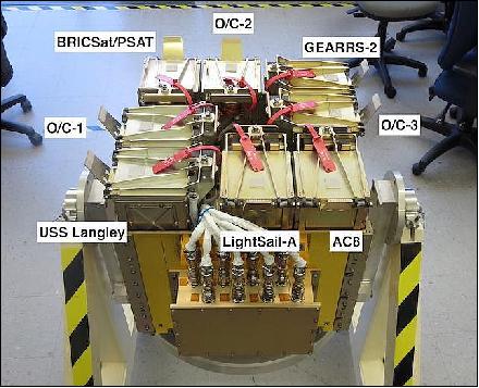
All CubeSats are integrated into 8 P-PODs (Poly-Picosatellite Orbital Deployers) which are contained in the NPSCuL (Naval Postgraduate School CubeSat Launcher), built by the NPS (Naval Postgraduate School). The NPSCuL together with the 8 P-PODs and 10 CubeSats is referred to as the ULTRASat (Unique Lightweight Technology and Research Auxiliary Satellite), and is attached to the Centaur upper stage's ABC (Aft Bulkhead Carrier). The assembled ULTRASat is shown in Figure NO TAG# the photo below ready for mate to the launch vehicle along with members of the ULTRASat team consisting of NPS, Office of Space Launch (OSL), United Launch Alliance (ULA) and Cal Poly. 15)
Orbit: BRICSat-P, as well as all secondary payloads, were released into an elliptical orbit, altitude of 350 km x 700 km, eccentricity=0.0253 and an inclination of 55º.
Mission Status
• August 2016: The µCAT (Micro-Cathode Arc Thruster), a micro-propulsion system developed by The GWU (George Washington University), seeks to provide a solution for the power and volume limitations of smaller CubeSats. Four Micro-Cathode thrusters have been successfully integrated and tested in space onboard the USNA (U.S. Naval Academy) 1.5 U CubeSat, BRICSat-P. This system will enable satellite developers to plan and build more ambitious and complex CubeSat missions. The thruster gives CubeSats (and other small satellites) the ability to perform orbital maneuvers, orbital corrections, and active attitude control capabilities. 16)
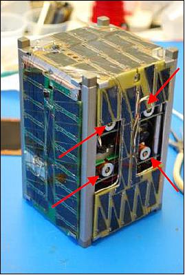
- The µCAT propulsion system was initially space-qualified on the BRICSat-P (Ballistically Reinforced Communication Satellite-Prototype). This satellite, a 1.5U CubeSat, and was launched on May 20, 2015 atop an Atlas V rocket. The back side of the satellite is shown in Figure 7.
- BRICSat-P's primary mission was to test the use of the µCAT thrusters on orbit. The thrusters were used for rudimentary attitude control. Initial reports show that the thrusters were capable of detumbling the satellite from an estimated 15 °/s to less than 1.5 °/s within the first 48 hours. This occurred without the use of any other passive or active attitude control systems. The satellite's rotation rate reached a level of less than 1 °/s on all axes after another 48 hours, which was the target detumble rate. Through these demonstrations, BRICSat-P validated the ability of the µCAT thrusters to provide a propulsive force in space by creating measurable difference in the spacecraft's rotation.
- With a total volume of < 8 cm3 per thruster head and a low power consumption of approximately 1 W at a firing rate of 10 Hz, the µCAT system is a compact and low power system that caters specifically to the small satellite community. Its small size allows it to be positioned in very compact spaces within the satellite and it fits between circuit boards, since the standard distance between PCBs in CubeSats is approximately 15 mm. The thruster can be used for precise pointing maneuvers as well as for general attitude and orbit control maneuvers such as detumbling of the spacecraft. The µCAT can be fired at higher rates (e.g. 50 Hz) allowing the system to function as main propulsion system. The highly ionized plasma produced by the discharge results in almost no back-flux to the satellite, a characteristic that is particularly important for missions with sensitive equipment such as optical systems.
- The relatively low power consumption and size of this propulsion system has the potential to greatly increase the capabilities of the future CubeSat missions. Adaptation of such technology can make CubeSats maneuverable in orbit, greatly increasing the mission envelope of these satellites, spanning from LEO operations to interplanetary missions. The first iteration of the design has been tested in space onboard BRICSat-P mission, and the follow-on BRICSat missions will demonstrate and characterize the enhanced capability of this propulsion system.
• June 21, 2015: BRICSat-P is currently in orbit but due to the power issues, a consistent communication has not yet been established. Some preliminary data has been downloaded from the satellite, and it shows that the satellite has successfully operated the propulsion system. Communication received from the CubeSat thus far has verified the thruster's ability to detumble. The preliminary data shows that the propulsion system was able to reduce initial tumbling from an estimated 30 º/s to within 1.5 º/s after 48 hours. This is accomplished without any other passive or active attitude control mechanism such as magnetic torque, permanent magnets, or hysteresis rods. The data showed that the two axes that are controlled directly by the propulsion system has reached the target rotation rate of 1.0 º/s at a much earlier time, and the intermediate axis is the only axis still above 1.0 º/s at the 48 hour mark. After another 48 hours, all three axes were stabilized to below 1.0 º/s. More data will give a better understanding of the performance of the propulsion system, but the preliminary results shows that the propulsion system functioned as designed, and quite effectively. 17)
• June 7, 2015: AMSAT announced that the BRICSat-P CubeSat was given the Oscar number Oscar 83. 18)
• May 21,2015: First signals of BRICSat-P were received by the AMSAT community. 19)
Sensor Complement (µCAT, APRS)
µCAT (Micro-Cathode Arc Thruster)
The MpNL (Micro-propulsion and Nanotechnology Laboratory) at GWU (The George Washington University) in Washington DC designed and developed a four-channel µCAT micro-propulsion subsystem that allows CubeSats and nanosatellites to provide maneuverability. The MpNL developed a µCAT in 2007. The technology used to create the µCAT was derived from the VAT (Vacuum Arc Thruster), which was identified as a valid form of spacecraft propulsion in the 1960s. Vacuum arc thrusters are ideal for small spacecraft because they are able to utilize small quantities of solid metal for the propellant. 20) 21) 22) 23)
The objective of µCAT is to create a small-satellite propulsion system that uses low-cost components, eliminates the use of pressurized systems, operates with low-power, is scalable and modular, and is safe for the satellite. The µCAT system consists of four thruster heads – each consisting of two coaxial electrodes that are separated by several millimeters of Electric Solid Propellant with a Magnetic Coil on the forward end of the thruster. Each thruster head measures 1 cm in diameter and 2.3 cm in length.
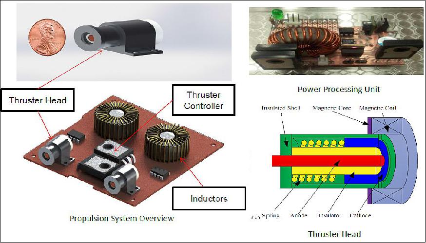
Thruster heads: The thruster heads consist of a coaxial anode and cathode with a ceramic insulator in between to prevent contact between the elements; an aluminum housing has been designed to encase the thruster components. The thruster creates an arc between an anode and cathode, similar to a spark plug. The cathode acts as the propellant. According to experiments done by the MpNL, the use of titanium increases the ion current by 3.25%, as opposed to nickel which only increases the ion current by 3%.1 Each of the four thrust heads has a nickel anode and titanium cathode, also known as a bi-modal micro-cathode arc thruster.
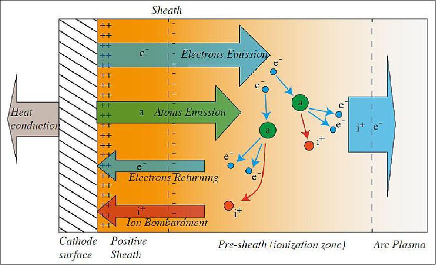
The anode is located in the center of the thruster while the titanium cathode material builds the external shell of the thruster. The solid propellant used in these thrusters can only ignite when an electric current is applied and only sustain operation as long as the current is present. This allows for precise control and a reliable ignition.
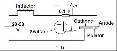
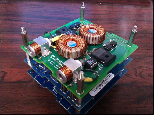
In the design of the µCAT there is an inductive energy system, the PPU (Power Processing Unit) as shown in Figure 10. The PPU is equipped with an IES (Inductive Energy Storage) circuit, which is a one channel thruster subsystem. This system utilizes an IGBT (Insulated-Gate Bipolar Transistor) to act as a semiconductor gate.
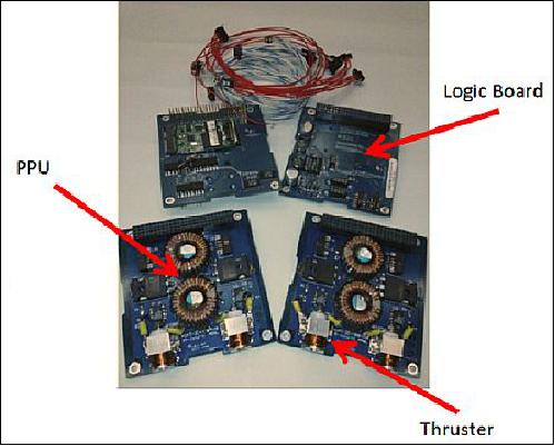
CU (Control Unit): Separate from the PPU are a series of PCBs (Printed Circuit Boards) that make up the CU. The CU controls the actions of the thrusters and consists of several PCBs with standalone microcontrollers to create a multichannel subsystem. They are modular in order to incorporate the power system and control system without any restrictive orientation. The CU contains a power distribution section, power connectors, a CubeSat Kit bus connection, and a subsystem interface. Within the subsystem interface there are three groups: the command signal input, the telemetry signal output, and the power supply input. Utilizing 6-36 VDC, the CU outputs impulses to all channels at a maximum firing rate of 55 Hz to regulate the pulses sent to the PPU to produce the thruster discharge. The entire system in shown in Figure 4.
Mission parameters: The focus of the mission is to integrate the μCAT into the CubeSat system to validate its capabilities. The thruster system must be able to detumble the CubeSat to a stable orientation and spin rate for several orbits, demonstrate the ability to spin around two axes, and perform a desired ΔV using a gyroscope and magnetometer. To allow the system to perform these maneuvers, the thrust head configuration must be optimized for peak performance. Prior to sending the CubeSat to orbit, it has to prove that it can withstand a series of vibrational and thermo-vacuum tests to ensure it is able to endure lift-off and the harsh conditions of space. Once the CubeSat is launched the thruster subsystem will be assessed based on its performance and ability to execute the desired tasks in orbit without consuming an inordinate amount of fuel or power.
The structure of the CubeSat itself had to remain within the mass limit of 2 kg (1.5U), leaving 1kg for the thruster subsystem. Due to the fact that the thruster system is only 600 g in total, a decision has been made to have four separate power units – rather than two units with a switch interface. In addition, the entirety of the outside is covered with solar panels to generate power.
The µCAT thrusters operate at frequencies between1-20 Hz, generating impulse bits of 1mNs per pulse and operate at a specific impulse of 2000 to 3000 seconds, much higher than conventional liquid-fueled thruster systems. The mass of the system with its individual thrusters and the central PPU (Propulsion Power Unit) is around 200 gram. Overall, for a 4 kg satellite, the system can deliver a ΔV of 300 m/s.
The detumble experiment is expected to take seven orbits before the satellite enters a stable attitude with a target stability of under 1º/s. The rotational experiment will operate the thrusters at a 22% duty cycle to spin up to 6 rpm with the satellite cameras acquiring photos of the operation of the thrusters.
APRS (Automatic Packet Reporting System)
BRICSat-P also carries two amateur communication payloads – the APRS transponder with a downlink at 437 MHz and an uplink at 145 MHz, and a PSK31 transponder with a 28.120 MHz uplink and standard UHF downlink on 435.350 MHz.
APRS is digital communications information channel for Ham radio. As a single national channel, it gives the mobile ham a place to monitor for 10 to 30 minutes in any area, at any time to capture what is happening in ham radio in the surrounding area. APRS was developed at USNA, which allows packet radio to track realtime events. It deviates markedly from the usual message- and text-transfer activity. Instead, APRS concentrates on the graphic display of station and object locations and movements. 24) 25)
References
1) Christopher Dinelli, Samudra Haque, Jin Hang, Michael Keidar, Kristen Castonguay,"Ballistic Reinforced Communication Satellite (BRICSat-P): The First Flight of an Electric Micropropulsion System for CubeSat Mission Applications," Proceedings of iCubeSat 2014, 3rd Interplanetary CubeSat Workshop, Pasadena, CA, USA, May 27-28, 2014, URL: https://icubesat.files.wordpress.com/2014/05/
icubesat-org_2014_b-2-4-bricsat-p_dinellie_201405281748.pdf
2) Joseph Lukas, George Teel, Samudra Hague, Alexey Shashurin, Michael Keidar, "Thruster Subsystem Design for the Ballistic Reinforced Communication Satellite (BRICSat-P)," Proceedings of the AIAA/USU Conference on Small Satellites, Logan, Utah, USA, August 2-7, 2014, Pre-Conference: CubeSat Developers' Workshop, paper: SSC14-WK-18, URL: http://digitalcommons.usu.edu/cgi/viewcontent.cgi?filename
=0&article=3155&context=smallsat&type=additional
3) Christopher Dinelli, Samudra Haque, Jin Hang, Michael Keidar, Kristen Castonguay, "Ballistic Reinforced Communication Satellite (BRICSat-P): The First Flight of an Electric Micropropulsion System for CubeSat Mission Applications," 4th Interplanetary CubeSat Workshop, South Kensington, London, UK, May 26-27, 2015, URL: http://icubesat.org/papers/2014-2/2014-b-2-4-ballistic-reinforced
-communication-satellite-bricsat-p-the-first-
flight-of-an-electric-micropropulsion-system-for-cubesat-mission-applications/, URL of Presentation : https://icubesat.files.wordpress.com/2014/05/icubesat
-org_2014_b-2-4-bricsat-p_dinellie_201405281748.pdf
4) Jeremy Straub, Samudra Haque, Christopher Kenji Dinelli, "Considering the educational benefits of a CubeSat program," URL: http://works.bepress.com/cgi/viewcontent.cgi?params=
/context/jeremy_straub/article/1366/type/native/&path_info=
5) Tomáš Urbanec, Petr Vágner, Miroslav Kasal, Ondřej Baran, "Communication and Data Handling System for BRICsat Satellite," 6th International Conference on RAST (Recent Advances in Space Technologies, June 12-14, 2013, Istanbul, Turkey, URL: http://www.aprs.org/PSK31/Brno-PSK31_2-PID2722925.pdf
6) "United Launch Alliance Successfully Launches X-37B Orbital Test Vehicle for the U.S. Air Force," ULA, May 20, 2015, URL: http://www.ulalaunch.com/ula-successfully-launches-afspc5.aspx
7) Ken Kremer, "X-37B Air Force Space Plane Launches on 4th Mystery Military Mission and Solar Sailing Test" Universe Today, May 20, 2015, URL: http://www.universetoday.com/120396/x-37b-air-force-space
-plane-launches-on-4th-mystery-military-mission-and-solar-sailing-test/
8) Stephanie Schierholz, Jason Davis, Loretta DeSio, "NASA's CubeSat Initiative Aids in Testing of Technology for Solar Sails in Space," NASA, May 20, 2015, Release 15-101, URL: http://www.nasa.gov/press-release/nasa-s-cubesat-
initiative-aids-in-testing-of-technology-for-solar-sails-in-space
9) Stephanie Schierholz, Tracy McMahan, "NASA Test Materials to Fly on Air Force Space Plane," NASA, May 6, 2015, Release 15-081, URL: http://www.nasa.gov/press-release/nasa-test
-materials-to-fly-on-air-force-space-plane
10) Patrick Blau, "AFSPC-05 Secondary Payloads," Spaceflight 101, URL: http://www.spaceflight101.com/afspc-05-secondary-payloads.html
11) "ELaNa XI CubeSat Launch on AFSPC-5," NASA, May 2015, URL: http://www.nasa.gov/sites/default/files/files/ELaNa-XI-Factsheet-508.pdf
12) "Atlas V AFSPC-5: ULTRASat CubeSat Summary," URL: http://www.ulalaunch.com/uploads/docs/Launch
/AtlasV_AFSPC-5_ULTRASat_CubeSat_descriptions.pdf
13) Christopher Dinelli, Samudra Haque, Jin Hang, Michael Keidar, Kristen Castonguay,"Ballistic Reinforced Communication Satellite (BRICSat-P): The First Flight of an Electric Micropropulsion System for CubeSat Mission Applications," Proceedings of iCubeSat 2014, 3rd Interplanetary CubeSat Workshop, Pasadena, CA, USA, May 27-28, 2014, URL: https://icubesat.files.wordpress.com/2014/05/
icubesat-org_2014_b-2-4-bricsat-p_dinellie_201405281748.pdf
14) Joseph Lukas, George Teel, Samudra Hague, Alexey Shashurin, Michael Keidar, "Thruster Subsystem Design for the Ballistic Reinforced Communication Satellite (BRICSat-P)," Proceedings of the AIAA/USU Conference on Small Satellites, Logan, Utah, USA, August 2-7, 2014, Pre-Conference: CubeSat Developers' Workshop, paper: SSC14-WK-18, URL: http://digitalcommons.usu.edu/cgi/viewcontent.cgi?filename
=0&article=3155&context=smallsat&type=additional
15) "CubeSat in the News -Atlas V ULTRASat Launch 2015," URL: http://www.cubesat.org/
16) Jonathan Kolbeck, Joseph Lukas, George Teel, Michael Keidar, Edward Hanlon, Jacob Pittman, Morgan Lange, Jin Kang, "µCAT Micro-Propulsion Solution for Autonomous Mobile On-Orbit Diagnostic System," Proceedings of the 30th Annual AIAA/USU SmallSat Conference, Logan UT, USA, August 6-11, 2016, paper: SSC16-V-7, URL: https://digitalcommons.usu.edu/cgi/viewcontent.cgi?
referer=&httpsredir=1&article=3374&context=smallsat
17) Samantha Hurley, George Teel, Joseph Lukas, Samudra Haque, Michael Keidar, Christopher Dinelli, Jin Kang, "Thruster Subsystem for the United States Naval Academy's (USNA) Ballistically Reinforced Communication Satellite (BRICSat-P)," This information was provided by Michael Keidar of GWU.
18) "US Naval Academy CubeSats Get OSCAR Numbers," AREL, June 7, 2015, http://warlock/news/us-naval-academy-cubesats-get-oscar-numbers
19) "BRICSat-P Telemetry," AMSAT, May 21, 2015, URL: http://www.pe0sat.vgnet.nl/2015/bricsat-p-telemetry/
20) Samantha Hurley, George Teel, Joseph Lukas, Samudra Haque, Michael Keidar, Christopher Dinelli, Jin Kang, "Thruster Subsystem for the United States Naval Academy's (USNA) Ballistically Reinforced Communication Satellite (BRICSat-P)," Joint Conference of 30th International Symposium on Space Technology and Science 34th International Electric Propulsion Conference and 6th Nano-satellite Symposium, Hyogo-Kobe, Japan, July 4 – 10, 2015
21) Michael Keidar, Taisen Zhuang, Alexey Shashurin, George Teel, Dereck Chiu, Joseph Lukas, Samudra Haque, Lubos Brieda, "Electric propulsion for small satellites," IOP Publishing, Plasma Physics and Controlled Fusion, Vol. 57, 2015, 014005, doi:10.1088/0741-3335/57/1/014005
22) Joseph Lukas, George Teel, SamudraHaque, Alexey Shashurin, Michael Keidar, "Thruster Subsystem Design for the Ballistic Reinforced Communication Satellite (BRICSat-P),"Proceedings of the 28th Annual AIAA/USU Conference on Small Satellites, Logan, Utah, USA, August 2-7, 2014, URL: http://digitalcommons.usu.edu/cgi/viewcontent.cgi?
filename=0&article=3155
&context=smallsat&type=additional
23) George Teel, Joseph Lukas, Samantha Hurley, Samudra Haque, Michael Keidar, Christopher Dinelli, Jin Kang, "Thruster Subsystem for the United States Naval Academy's (USNA) Ballistically Reinforced Communication Satellite (BRICSat-P)," 34th IEPC (International Electric Propulsion Conference), Kobe city, Hyogo, Japan, July 6-10, 2015
24) Bob Bruninga, "Automatic Packet Reporting System," URL: http://www.aprs.org/
25) "Automatic Packet Reporting System (APRS)," ARRL, URL: http://www.arrl.org/automatic-packet-reporting-system-aprs
The information compiled and edited in this article was provided by Herbert J. Kramer from his documentation of: "Observation of the Earth and Its Environment: Survey of Missions and Sensors" (Springer Verlag) as well as many other sources after the publication of the 4th edition in 2002. - Comments and corrections to this article are always welcome for further updates (eoportal@symbios.space).
Spacecraft Launch Mission Status Sensor Complement References Back to top