BioSentinel nanosatellite on EM-1
EO
NASA
Operational (extended)
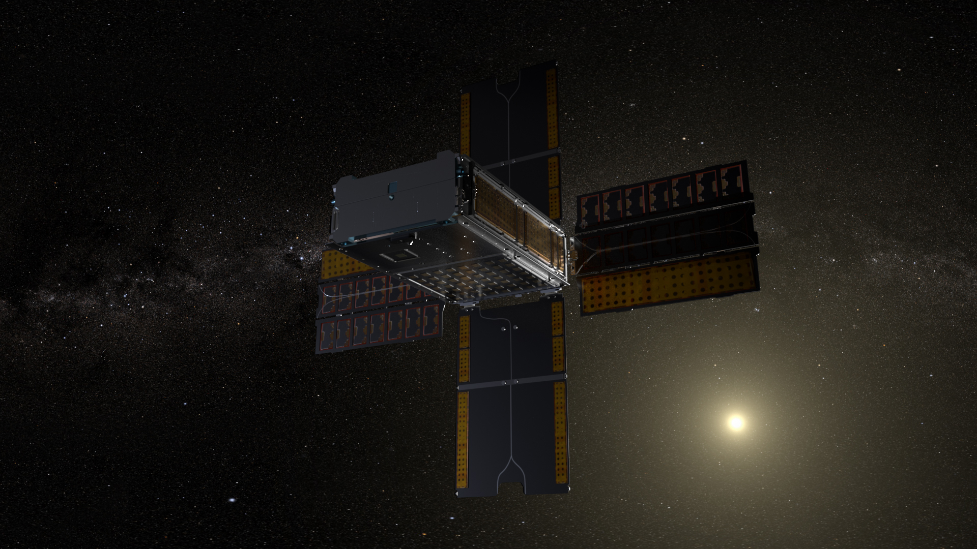
BioSentinel is an astrobiology mission, selected to help understand the effect of solar radiation on genetic material. The main experiment involves detecting and measuring the damage to DNA in budding yeast, whilst comparing it to the direct radiation exposure from space. It is hoped that BioSentinel will prove key to evaluating the dangers posed to humans embarking on deep space travel. BioSentinel was launched in November 2022 onboard the Artemis 1 mission.
Quick facts
Overview
| Mission type | EO |
| Agency | NASA |
| Mission status | Operational (extended) |
| Launch date | 16 Nov 2022 |
| CEOS EO Handbook | See BioSentinel nanosatellite on EM-1 summary |
Summary
Mission Capabilities
The Biosentinel satellite contains three main instruments: one to detect genetic damage in the organism and two to quantify concurrent radiation exposure.
The biosensor contains the organism, Saccharomyces cerevisiae (baker’s yeast), and records instances of double-strand-break (DSB) caused by space radiation.
Biosentinel is also equipped with TimePix radiation sensors, developed by the RadWorks group of the Johnson Space Center. The Linear Energy Transfer (LET) spectrometer measures the particle energy and photon count while the associated linear energy transfer is quantified by a Total Ionising Dose (TID) dosimeter. This will be subsequently compared to the recorded instances of DSB to assess the correlation between space radiation and damage to DNA.
Performance Specifications
Yeast’s role as the test organism derives from two key factors. Its highly regenerative capability means it can survive multiple instances of DSB. Its modes of repair are also very similar to human modes, and so they provide an accurate representation of how human cells might fare in deep space environments. The radiation detector is highly sensitive, able to detect radiation flux spikes of over 1000 times the background level during a single solar particle event (SPE). During such SPEs, ionising doses of 4 to 5 krads are anticipated, requiring a highly specialised LET spectrometer.
BioSentinel’s flight path will initially take it past the moon and then subsequently into an Earth trailing, Heliocentric orbit.
Space and Hardware Components
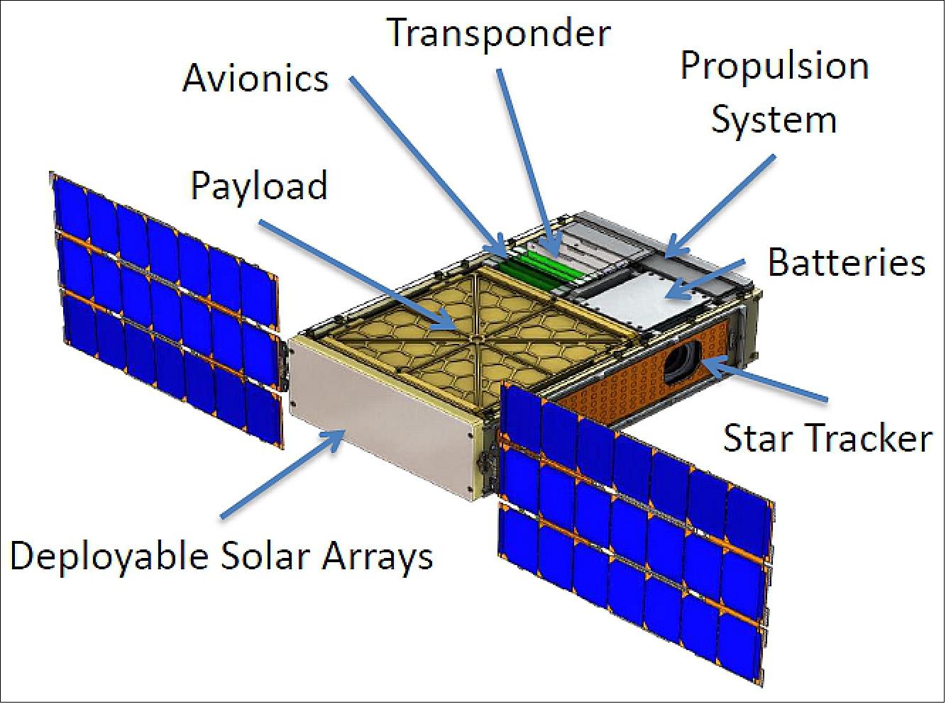
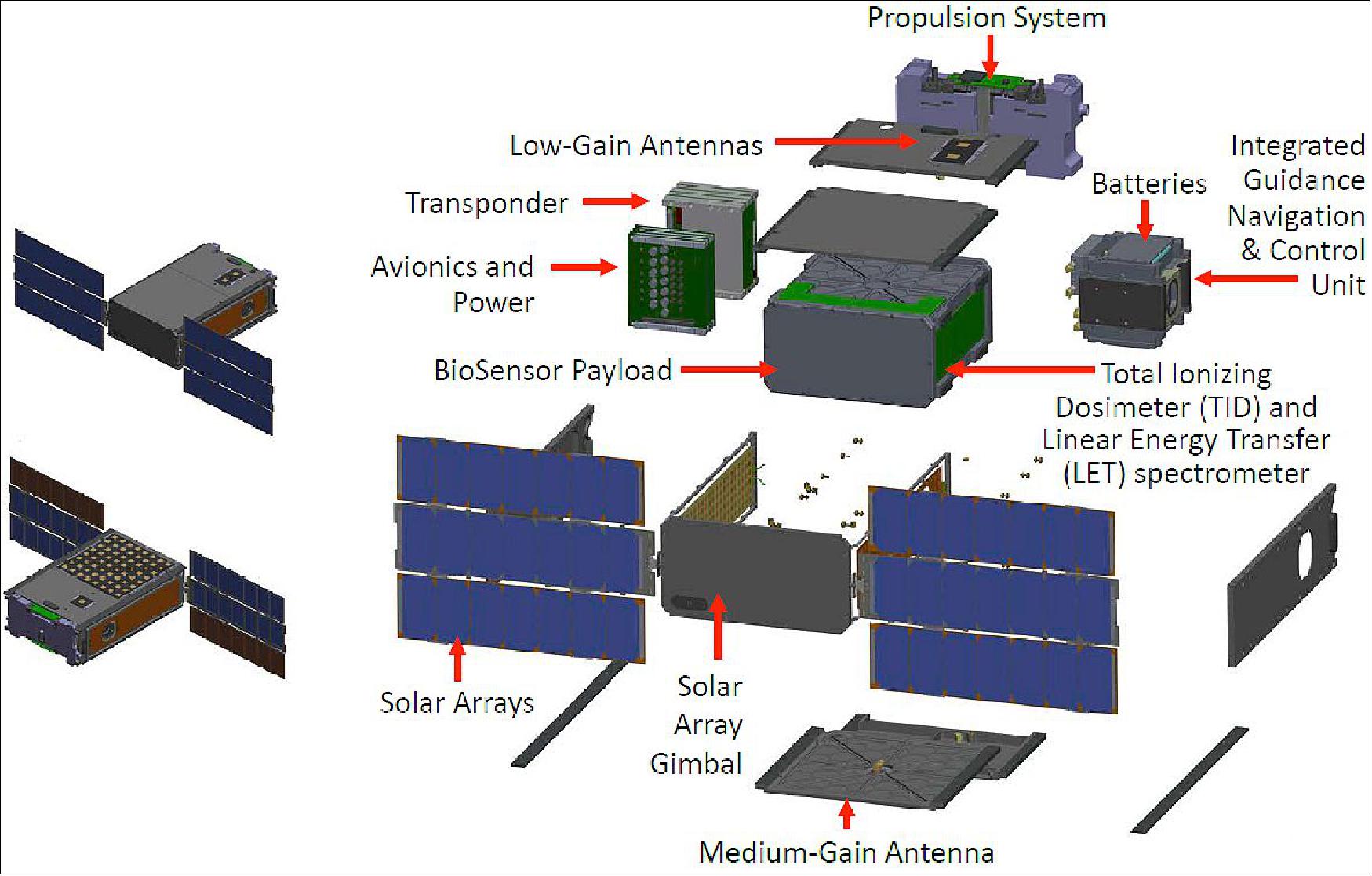
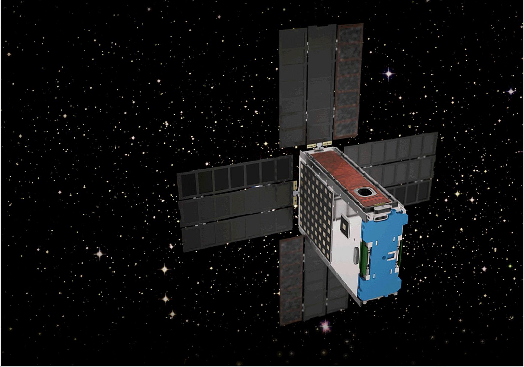
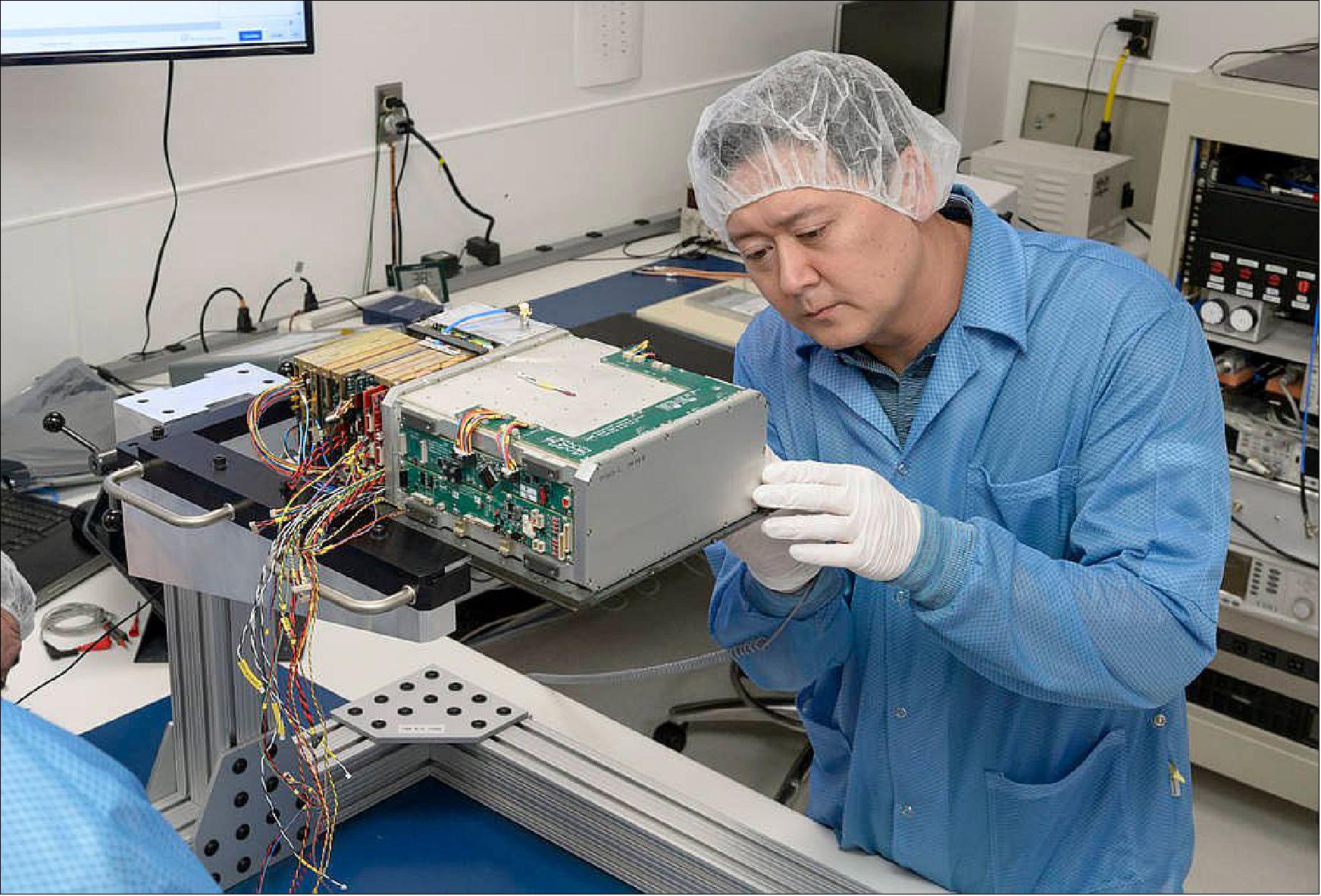
The BioSentinel satellite is housed in a 6U cubesat bus. Four of the units are reserved for scientific instrumentation, including a radiation dosimeter and a three-colour spectrometer. One unit is dedicated to housing the integrated attitude control thruster, combining cold propellant tanks, transfer lines and seven nozzles. The remaining units house the electrical power system (EPS), command and data handling avionics (C&CH) and the attitude detrimental and control subsystem (ADCS).
Electrical power is produced via a deployable 30 watt solar panel. Throughout the entire mission, science data and spacecraft telemetry will be stored onboard and then later downloaded to the ground. Such a transmission will be made via an Iris transponder, operation in X-band.
BioSentinel nanosatellite on EM-1
Spacecraft Launch Sensor Complement Ground Segment References
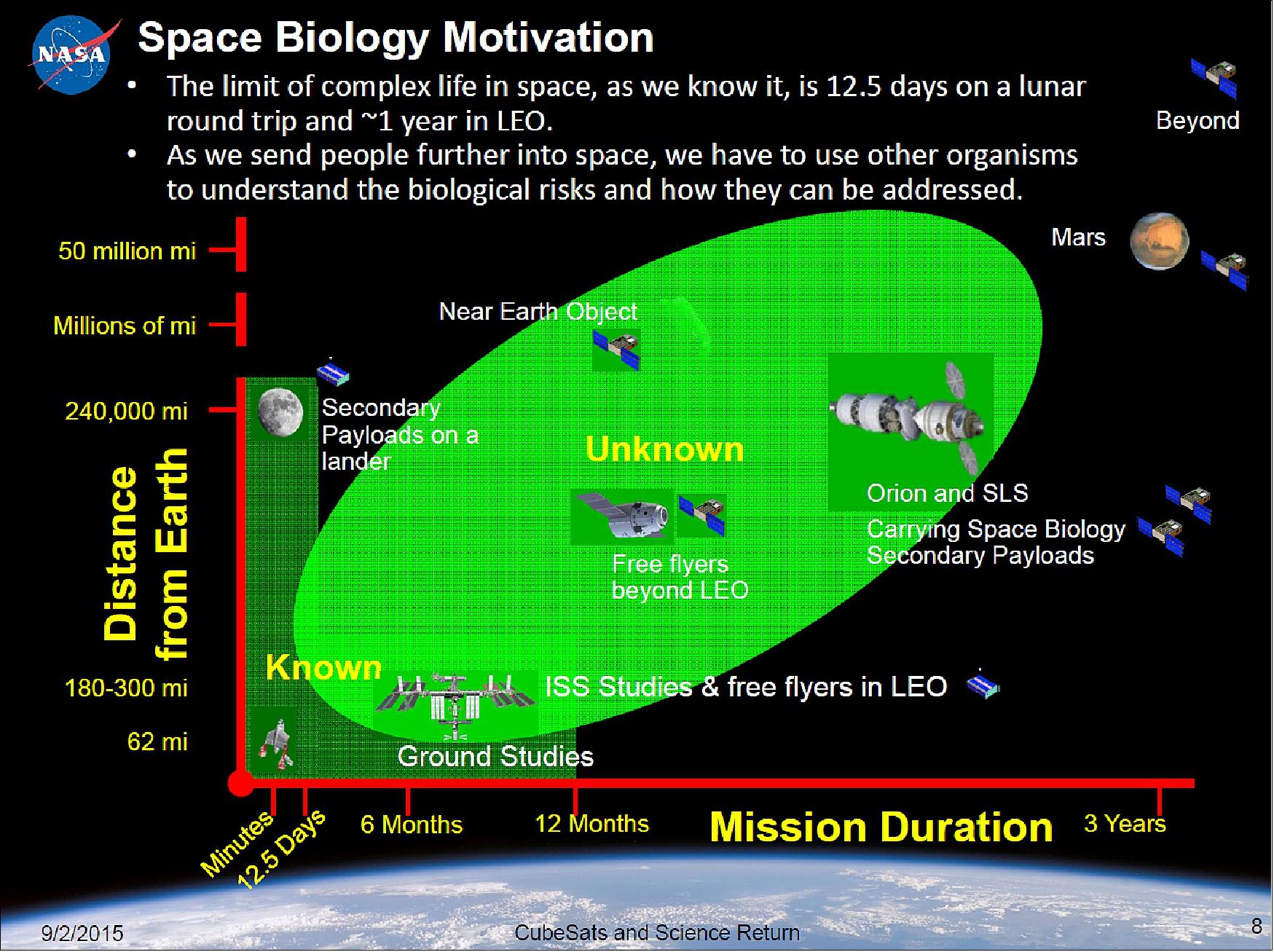
BioSentinel is a 6U nanosatellite under development at NASA/ARC (Ames Research Center). The mission was selected in 2013 as one of the secondary payloads to fly the nanosatellite as a secondary payload aboard NASA’s SLS (Space Launch System) Exploration Mission-1 (EM-1), scheduled for launch in 2019/20. For the first time in over forty years, direct experimental data from biological studies beyond LEO (Low Earth Orbit) will be obtained during BioSentinel’s 12 to the 18-month mission. BioSentinel will measure the damage and repair of DNA in a biological organism and compare that to information from onboard physical radiation sensors. This data will be available for validation of existing models and for extrapolation to humans. 1) 2)
BioSentinel project objectives: 3)
• The AES (Advanced Exploration Systems) Program Office selected BioSentinelto to fly on the SLS EM-1 (Exploration Mission) as a secondary payload
- Payload selected to help fill Strategic Knowledge Gaps in Radiation effects on Biology
- Current EM-1 Launch Readiness Date (LRD): 2019/2020
• Key BioSentinel project objectives
- Develop a deep-space nanosatellite capability
- Develop a radiation biosensoruseful for other missions
- Define & validate SLS secondary payload interfaces and accommodations for a biological payload
• Collaborate with two other AES-selected missions (non-biological) for EM-1
- NEA Scout (Near Earth Asteroid) Scout (MSFC)
- Lunar Flashlight (JPL).
BioSentinel will conduct the first study of biological response to space radiation outside LEO in over 40 years. BioSentinel will address strategic knowledge gaps related to the biological effects of space radiation and will provide an adaptable platform to perform human-relevant measurements in multiple space environments in the future. Yeast is the ideal organism for this mission because of its spaceflight heritage, it is highly capable of repairing DSBs (Double Strand Breaks), and it can be stored in stasis for a long period of time.
Moreover, the DSB repair mechanisms in yeast are well-studied and highly similar to those in human cells. BioSentinel's results will be critical for improving the interpretation of the effects of space radiation exposure, and for reducing the risk associated with long-term human exploration.
The BioSentinel experiment will use the organism Saccharomyces cerevisiae (yeast) to report DNA DSB (Double-Strand-Break) events that result from space radiation. DSB repair exhibits striking conservation of repair proteins from yeast to humans. The flight strain will include engineered genetic defects that prevent growth and division until a radiation-induced DSB activates the yeast’s DNA repair mechanisms. The triggered culture growth and metabolic activity directly indicate a DSB and its repair.
The yeast will be carried in the dry state in independent microwells with support electronics. The measurement subsystem will sequentially activate and monitor wells, optically tracking cell growth and metabolism. BioSentinel will also include TimePix radiation sensors implemented by the RadWorks group of NASA/JSC (Johnson Space Center). Dose and LET (Linear Energy Transfer) data will be compared directly to the rate of DSB-and-repair events measured by the S. cerevisiae (yeast) biosentinels.
BioSentinel will mature nanosatellite technologies to include: deep space communications and navigation, autonomous attitude control and momentum management, and micropropulsion systems to provide an adaptable nanosatellite platform for deep space uses. 5) 6)
Spacecraft
The BioSentinel spacecraft is being implemented using lessons learned from both the NASA/ARC nanosatellite line as well as from the LADEE (Lunar Atmosphere and Dust Environment Explorer) mission.
The use of small spacecraft in interplanetary missions promises to reduce mission costs and allow more planetary science missions to be conducted. One critical technology to enable these missions are miniaturized propulsion systems, capable of both translational manoeuvres and attitude control.
RF communications: 7)
Higher data rate CubeSats are transitioning away from Amateur Radio bands to higher frequency bands. A high-level communication architecture for future space-to-ground CubeSat communication was proposed within NASA/GSFC (Goddard Space Flight Center). This architecture addresses CubeSat direct-to-ground communication, CubeSat to Tracking Data Relay Satellite System (TDRSS) communication, CubeSat constellation with Mothership direct-to-ground communication, and CubeSat Constellation with Mothership communication through KSA (K-band Single Access).
A study has been performed to explore this communication architecture, through simulations, analyses, and identifying technologies, to develop the optimum communication concepts for CubeSat communications. The RF communications network is described in the Ground Segment chapter.
Cold Gas Thrusters: 8)
A cold gas thruster is a propulsion system in which the propellant does not undergo combustion or electromagnetic acceleration. The propellant is held under pressure in the thruster and released through a nozzle to generate thrust. Such systems have lower specific impulses than combustion-based thrusters or electric thrusters, meaning that they generate less total impulse per unit mass of propellant. However, cold gas thrusters may use inert propellants, which reduces handling risks and have relatively low power consumption compared to electric thrusters.
Cold gas thrusters have been previously used on CubeSats. The first CubeSat-sized spacecraft known to employ a cold gas thruster in space was the MEPSI (Microelectromechanical System-based PICOSAT Inspector ). This mission involved a pair of spacecraft, deployed in 2006, one of which was equipped with a miniature cold gas thruster. The thruster was used to manoeuvre the first spacecraft relative to the second spacecraft and achieved a total ΔV of 0.4 m/s.
In 2014, a pair of cold gas attitude control thrusters were developed for the INSPIRE mission, and a pair of 3U CubeSats was developed by the Jet Propulsion Laboratory to demonstrate small satellite capabilities beyond Earth orbit.
In 2015, a cold gas thruster was demonstrated in Low Earth Orbit on the POPSAT-HIP1 spacecraft. This propulsion system used pressurized Argon to provide between 2.25 and 3 m/s of ΔV. The BioSentinel thruster draws heavily on heritage from the INSPIRE attitude control thrusters and employs the same solenoid valves and propellant.
Design overview: The structure of the thruster consists of a 3D-printed component and five steel manifolds attached to the printed component and sealed with O-rings. The 3D-printed structure is printed using the SLA (Selective Laser Ablation) technique and is made from Accura Bluestone. Bluestone is a ceramic-like composite with a relatively high ultimate tensile strength of 66 MPa. The system is shown in Figure 4.
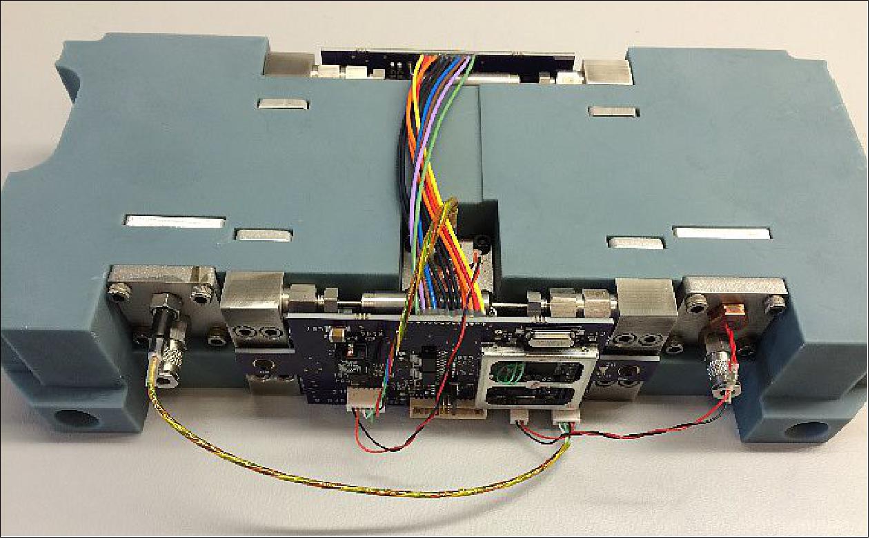
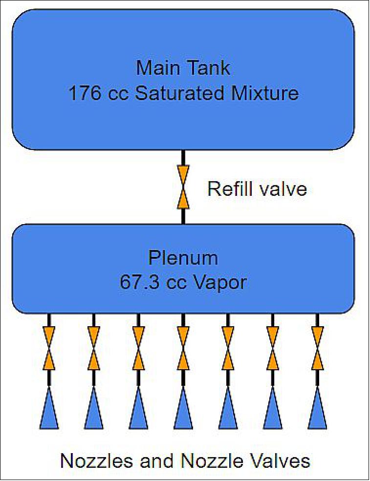
The printed structure contains two propellant tanks, the main tank and the plenum, as well as the seven nozzles and the propellant feed pipes. The main tank stores the majority of the propellant (up to 200 grams) as a saturated liquid-vapour mixture, while the plenum stores a smaller amount (up to 2 grams) as a vapour alone. The nozzles are supplied directly from the plenum. This arrangement allows the pressure behind the nozzles to be more precisely controlled and prevents liquid from entering any of the nozzles.
Eight miniature solenoid valves are used to control propellant flow. One valve controls flow from the main tank into the plenum, and each of the other seven valves control flow from the plenum to one of the seven nozzles. These valves are attached with compression fittings to two of the steel manifolds.
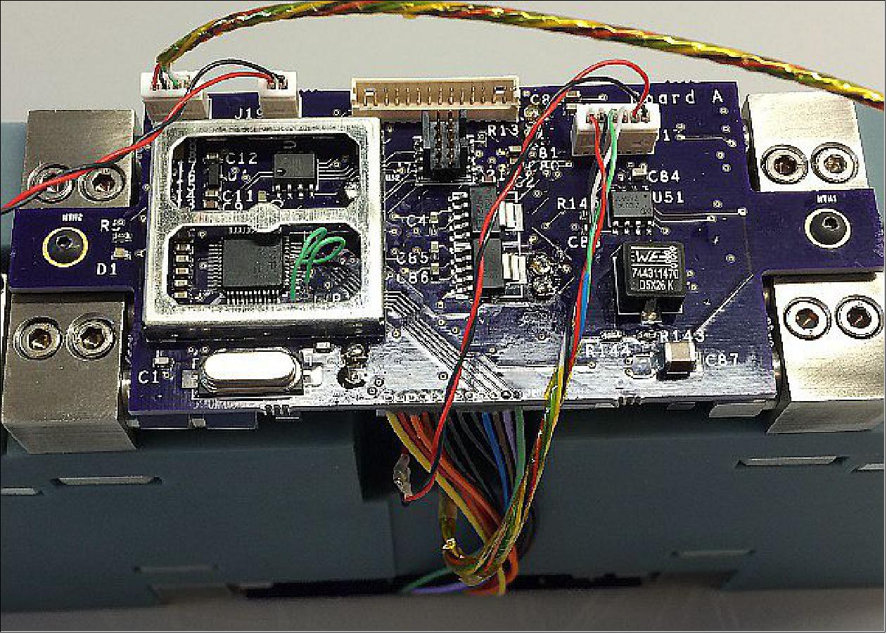
Electronics: The thruster is equipped with two pressure transducers and two thermistors, which are threaded into the steel manifolds. One pair of sensors is allocated to each propellant tank, so the pressure and temperature of each tank are sampled periodically. The thruster has two printed circuit boards, attached to the two valve manifolds. Each manifold holds four valves, and the electrical leads of these valves are soldered directly into plated holes in the circuit boards. These boards contain timing circuits to supply the correct voltage to the valves over very precise intervals.
One of the circuit boards also contains an LPC1549 microcontroller, which operates the thruster. The microcontroller operates the power switches that feed the solenoid valves, reads data from the sensors, and communicates with the BioSentinel flight computer over a serial port. The Pearl Single Board Computer is used as the flight computer along with the NAND flash memory of DDC (Data Device Corporation). DDC’s 192 Gbit NAND flash provides the smallsat spacecraft with compact, high-density memory, along with the advantages that a 24-bit bus configuration provides, allowing the use of TMR (Triple Modular Redundancy) error correction, for seamless operation without failure. DDC’s NAND flash is radiation hardened with radiation mitigation RAD-PAK® technology, offering best-in-class spot shielding. 9)
RAD-PAK® enables DDC to deliver the latest commercially available microelectronics in a space-qualified package, providing designers with a high-performance space-grade solution at a reduced cost. RAD-PAK®-based solutions offer a total dose immunity of 100 krads or higher and have been qualified by NASA, ESA, JAXA and thousands of missions for over 20 years without any flight failures.
Thruster concept of operations: Upon deployment from the launch vehicle, the main tank will contain the entire propellant load, and the plenum will be at vacuum. Prior to thruster operation, the plenum will be filled from the main tank until it reaches 95% of the main tank pressure. As the thruster is operated, the plenum pressure will fall as propellant is consumed. When the plenum pressure falls below a user-defined threshold, the thruster ceases operations and refills the plenum from the main tank. This threshold is nominally set to 80% of the current main tank pressure. Once the plenum is refilled, the thruster resumes normal operations. Approximately two seconds of continuous firing is needed to reduce the pressure from 95% to 80%, and approximately three seconds is needed to refill the plenum back to 95% when operating at 25ºC.
An engineering unit has been built and tested on a custom micropropulsion test stand in the Georgia Tech (Georgia Institute of Technology) Space Systems Design Lab.
Development Status
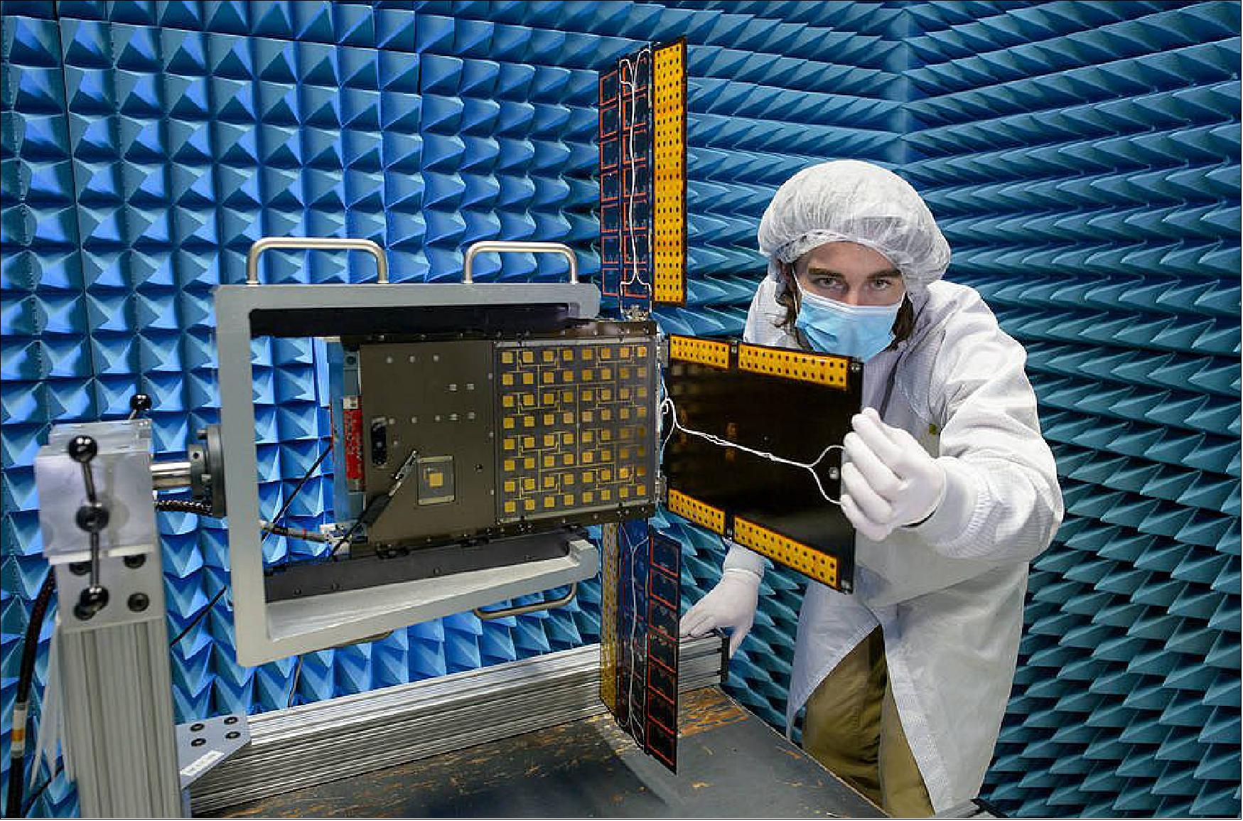
• April 2, 2021: BioSentinel gets a step closer to flight. Having completed assembly and a battery of tests, the BioSentinel team at NASA’s Ames Research Center in California’s Silicon Valley is in the final stretch of preparations to ship the spacecraft to NASA’s Kennedy Space Center in Florida for launch. BioSentinel’s deep space flight will go past the Moon and into an orbit around the Sun. It’s one of 13 CubeSats that will launch aboard Artemis I, the first flight of the Artemis program’s Space Launch System. 10)
Launch
BioSentinel 6U CubeSat will fly as a secondary payload on the Artemis-1 mission, originally known as the Orion EM-1 (Exploration Mission) of the SLS (Space Launch System), with an expected launch in the second half of 2021. The launch will be from Launch Complex 39-B at the Kennedy Space Center, Cape Canaveral, FL. 11)
Secondary Payloads of Orion/EM-1
The first flight of NASA’s new rocket, SLS ( Space Launch System), will carry 13 CubeSats/Nanosatellites to test innovative ideas along with an uncrewed Orion spacecraft in 2020. These small satellite secondary payloads will carry science and technology investigations to help pave the way for future human exploration in deep space, including the journey to Mars. SLS’ first flight, referred to as EM-1 (Exploration Mission-1 ), provides the rare opportunity for these small experiments to reach deep space destinations, as most launch opportunities for CubeSats are limited to low-Earth orbit. 12) 13)
The secondary payloads, 13 CubeSats, were selected through a series of announcements of flight opportunities, a NASA challenge and negotiations with NASA’s international partners.
NASA selected two payloads through the NextSTEP (Next Space Technologies for Exploration Partnerships) Broad Agency Announcement of May 5, 2015:
• LunIR ⟨originally called Skyfire) - Lockheed Martin Space Systems Company, Denver, Colorado, will develop a 6U CubeSat to perform a lunar flyby of the moon, taking sensor data during the flyby to enhance our knowledge of the lunar surface. LunIR will test a new technology mid-wave infrared camera and micro-cryocooler. LunIR also includes a visible imager.
• Lunar IceCube - Morehead State University, Kentucky, will build a 6U CubeSat to search for water ice and other resources at a low orbit of only 62 miles above the surface of the moon. This CubeSat will orbit the Moon and prospect for water and other volatiles in lunar regolith using BIRCHES (Broadband Infrared Compact High-Resolution Exploration Spectrometer) developed at NASA/GSFC.
Three payloads were selected by NASA’s Human Exploration and Operations Mission Directorate:
• NEA Scout (Near-Earth Asteroid Scout), the 6U CubeSat of NASA/MSFC/JPL will perform reconnaissance of an asteroid, take pictures and observe its position in space
• BioSentinel - a 6U CubeSat of NASA/ARC will use yeast to detect, measure and compare the impact of deep space radiation on living organisms over long durations in deep space.
• Lunar Flashlight - a 6U CubeSat of NASA/JPL/MSFC will look for ice deposits and identify locations where resources may be extracted from the lunar surface
Two payloads were selected by NASA’s Science Mission Directorate:
• CuSP – a 6U CubeSat of the SwRI (Southwest Research Institute) “space weather station” to measure particles and magnetic fields in space, testing the practicality of a network of stations to monitor space weather
• LunaH-Map a 6U CubeSat of Arizona State University will map hydrogen within craters and other permanently shadowed regions throughout the moon’s south pole
Three additional payloads were determined through NASA’s Cube Quest Challenge – sponsored by NASA’s Space Technology Mission Directorate and designed to foster innovations in small spacecraft propulsion and communications techniques. CubeSat builders will vie for a launch opportunity on SLS’ first flight through a competition that has four rounds, referred to as ground tournaments, leading to the selection in 2017 of the payloads to fly on the mission.
• Cislunar Explorers, Cornell University, Ithaca, New York. Cislunar Explorers’ concept consists of a pair of spacecraft on a mission to orbit the moon. These two spacecraft are mated together as a 6U CubeSat. After deployment from the launch vehicle, they will split apart and each give their initial rotation in the process of decoupling.
• CU-E3(CU Earth Escape Explorer), a 6U CubeSat of the University of Colorado in Boulder, CO. The CU-E3 mission will use a lunar gravity assist maneuver to place the CubeSat in a heliocentric orbit that trails the Earth at a distance > 1AU (Astronomical Unit). The distance between the Earth and the spacecraft will gradually increase over time, reaching 27 million km by the end of its one-year mission.
• Team Miles, Team Miles is led by the company Fluid and Reason LLC. Team Miles is a group of citizen scientists and engineers that initially came together through Tampa Hackerspace in Florida – all participants in the community, nonprofit workshop. Team Miles is a 6U CubeSat to demonstrate navigation in deep space using innovative plasma thrusters. Use of a software defined S-band radio to communicate with Earth.
Overview of the 10 selected US secondary missions for the inaugural Orion/EM-1 test flight plus three CubeSats from international partners 14) 15)
NASA has also reserved three slots for payloads from international partners. These are:
• EQUULEUS (EQUilibriUm Lunar-Earth point 6U Spacecraft) of ISSL (Intelligent Space Systems Laboratory) of the University of Tokyo and JAXA. EQUULEUS will help scientists understand the radiation environment in the region of space around Earth by imaging Earth’s plasmasphere and measuring the distribution of plasma that surrounds the planet. This opportunity may provide important insight for protecting both humans and electronics from radiation damage during long space journeys. It will also demonstrate low-energy trajectory control techniques, such as multiple lunar flybys, within the Earth-Moon region.
• OMOTENASHI (Outstanding MOon exploration TEchnologies demonstrated by NAno Semi-Hard Impactor) of JAXA. JAXA will use the OMOTENASHI to demonstrate the technology for low-cost and very small spacecraft to explore the lunar surface. This technology could open up new possibilities for future missions to inexpensively investigate the surface of the moon. The CubeSat will also take measurements of the radiation environment near the moon as well as on the lunar surface.
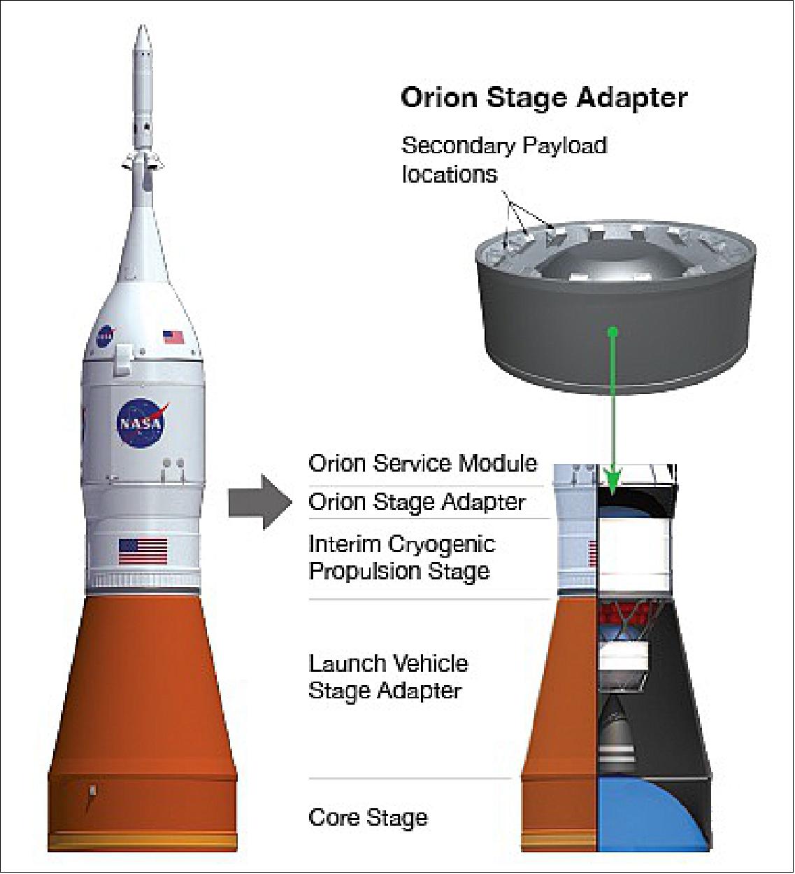
• ArgoMoon. The Italian company Argotec is building the ArgoMoon CubeSat under the Italian Space Agency (ASI) internal review and approval process. ArgoMoon will demonstrate the ability to perform operations in close proximity of the ICPS ( Interim Cryogenic Propulsion Stage), which will send Orion onto its lunar trajectory. It should also record images of the ICPS for historical documentation and to provide valuable mission data on the deployment of other CubeSats. Additionally, this CubeSat should test optical communication capabilities between the CubeSat and Earth.
All the CubeSats will ride to space inside the OSA (Orion Stage Adapter), which sits between the ICPS (Interim Cryogenic Propulsion Stage) and Orion (Figure 12). The CubeSats will be deployed following Orion separation from the upper stage and once Orion is a safe distance away.
The SPIE ( Spacecraft and Payload Integration and Evolution) office is located at NASA/MSFC (Marshall Space Flight Center) in Huntsville, Alabama, which handles the integration of the secondary payloads.
These small satellites are designed to be efficient and versatile—at no heavier than 14 kg, they are each about the size of a boot box and do not require any extra power from the rocket to function. The science and technology experiments enabled by these small satellites may enhance our understanding of the deep space environment, expand our knowledge of the moon, and demonstrate technology that could open up possibilities for future missions. 16)
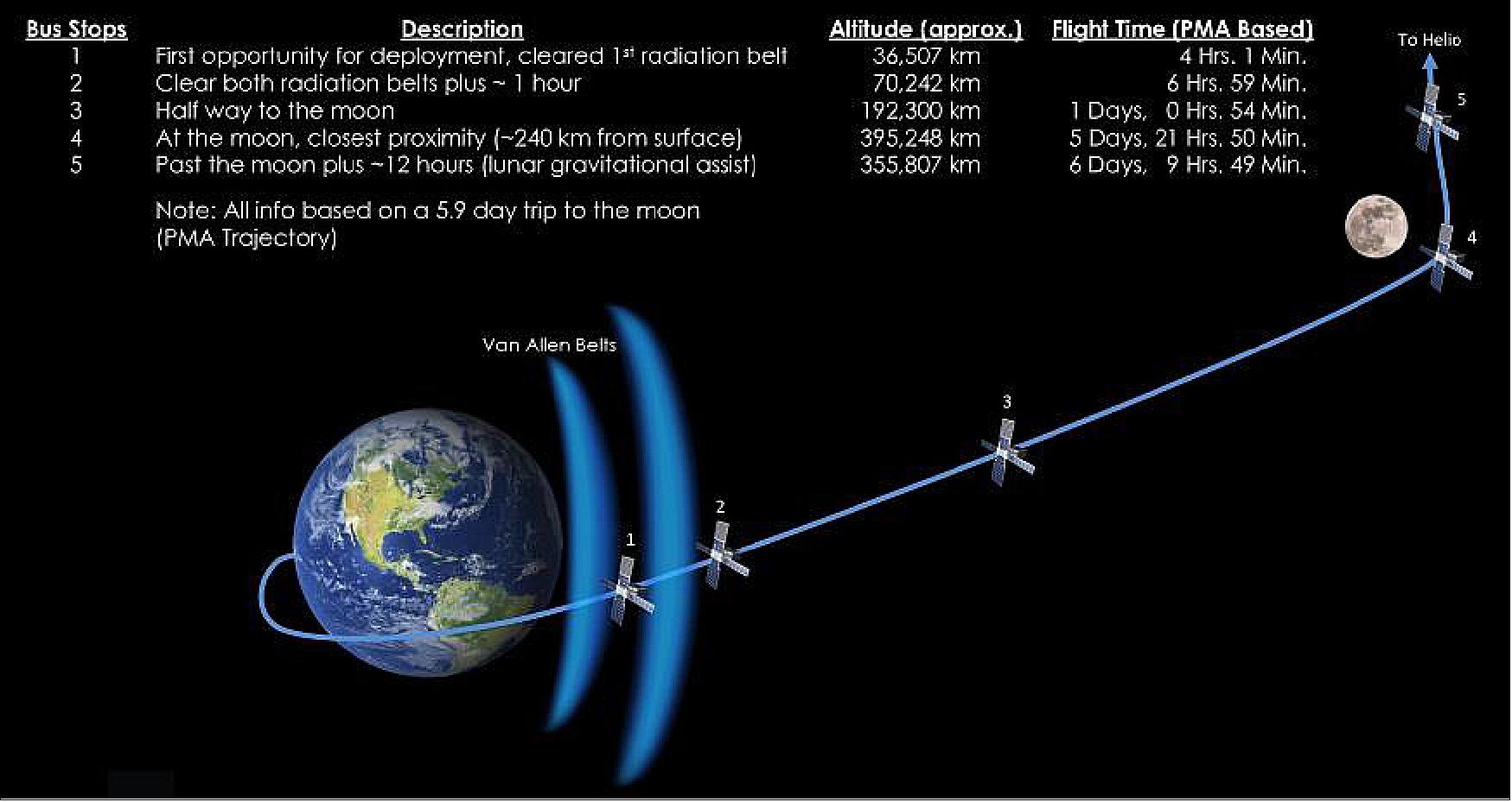
A key requirement imposed on the EM-1 secondary payload developers is that the smallsats do not interfere with Orion, SLS or the primary mission objectives. To meet this requirement, payload developers must take part in a series of safety reviews with the SLS Program’s Spacecraft Payload Integration & Evolution (SPIE) organization, which is responsible for the Block 1 upper stage, adapters and payload integration. In addition to working with payload developers to ensure mission safety, the SLS Program also provides a secondary payload deployment system in the OSA (Orion Space Adapter). The deployment window for the CubeSats will be from the time ICPS disposal manoeuvre is complete (currently estimated to require about four hours post-launch) to up to 10 days after launch. 17)
Deployment windows of secondary payloads: The smallsats manifested on EM-1 will undertake a diverse variety of experiments and technology demonstrations. Seven payloads will be deployed after the ICPS has cleared the first Van Allen Radiation Belt (bus stop 1, Figure 11).
• JAXA, the Japanese Space Agency, will have two smallsats deployed at the first stop: OMOTENASHI will land the smallest lander to date on the lunar surface to demonstrate the feasibility of the hardware for distributed cooperative exploration systems. If this mission is successful, Japan will be the fourth nation to successfully land a mission on the Earth’s moon. The other JAXA payload, EQUULEUS, will fly to a libration orbit around the EML2 (Earth-Moon L2) point and demonstrate trajectory control techniques within the sun-Earth-moon region for the first time by a smallsat.
• Lunar Flashlight is a NASA/JPL ( Jet Propulsion Laboratory) mission that will look for ice deposits and identify locations where resources may be extracted from the lunar surface.
• The NASA/ARC ( Ames Research Center) developed the BioSentinel mission a yeast radiation biosensor that will measure the effects of space radiation on DNA.
• ArgoMoon, sponsored by the Agenzia Spaziale Italiana (ASI), will perform proximity operations with the ICPS post-disposal and record imagery of engineering and historical significance — as well as of the Earth and moon — by testing an advanced software imaging recognition system using high-definition cameras.
• Cislunar Explorers, a team from Cornell University in Ithaca, New York, competing in NASA’s Cube Quest Centennial Challenge competition, has designed a 6U CubeSat that will split into two smaller spacecraft that will orbit the moon using a novel propulsion system of inert water to carry out gravity assists with the moon, and then be captured into lunar orbit.
• Finally, Lunar Icecube, developed by Morehead State University in Kentucky, will search for water in ice, liquid and vapour forms as well as other lunar volatiles from a low-perigee, highly inclined lunar orbit using a compact infrared spectrometer.
• About 90 minutes after the ICPS clears the first Van Allen Belt, the NEA Scout (Near Earth Asteroid) Scout, a NASA/MSFC (Marshall Space Flight Center) mission equipped with a solar sail to rendezvous with an asteroid, will be deployed. NEA Scout will gather detailed imagery and observe the asteroid’s position in space.
• After the ICPS has cleared both radiation belts, the LunaH-Map (Lunar-Polar Hydrogen Mapper) payload from Arizona State University will be released. LunaH-Map will help scientists understand the quantity of hydrogen-bearing materials in cold traps in permanently shaded lunar craters via low-altitude flybys of the moon’s south pole.
• About one hour after clearing the radiation belts (bus stop 2, Figure 11), Lockheed Martin’s LunIR spacecraft, a technology demonstration mission that will perform a lunar flyby, will be deployed. Using a miniature high-temperature MWIR (Mid-Wave Infrared) sensor to collect spectroscopy and thermography data, LunIR will provide data related to surface characterization, remote sensing and site selection for lunar future missions.
About 12 hours after the ICPS passes the moon (bus stop 5, Figure 11) and uses its gravity to enter heliocentric orbit, the final three smallsats will be released.
• The CuSP (CubeSat Mission to Study Solar Particles) mission of SwRI (Southwest Research Institute) in San Antonio, Texas, will study the sources and acceleration mechanisms of solar and interplanetary particles in near-Earth orbit, support space weather research by determining proton radiation levels during ESP (Solar Energetic Particle) events and identifying suprathermal properties that could help predict geomagnetic storms.
• Team Miles, of Miles Space, LLC, of Tampa, Florida, another Cube Quest competitor, has a mission that will fly autonomously using a sophisticated onboard computer system. The spacecraft will be propelled by evolutionary plasma thrusters.
• The final Cube Quest entrant, the University of Colorado CU-E3 (Earth Escape Explorer), is a CubeSat from the University of Colorado in Boulder, Colorado, that will use solar radiation pressure rather than an onboard propulsion system.
Sensor Complement (BioSensor, LET Spectrometer, TID Dosimeter)
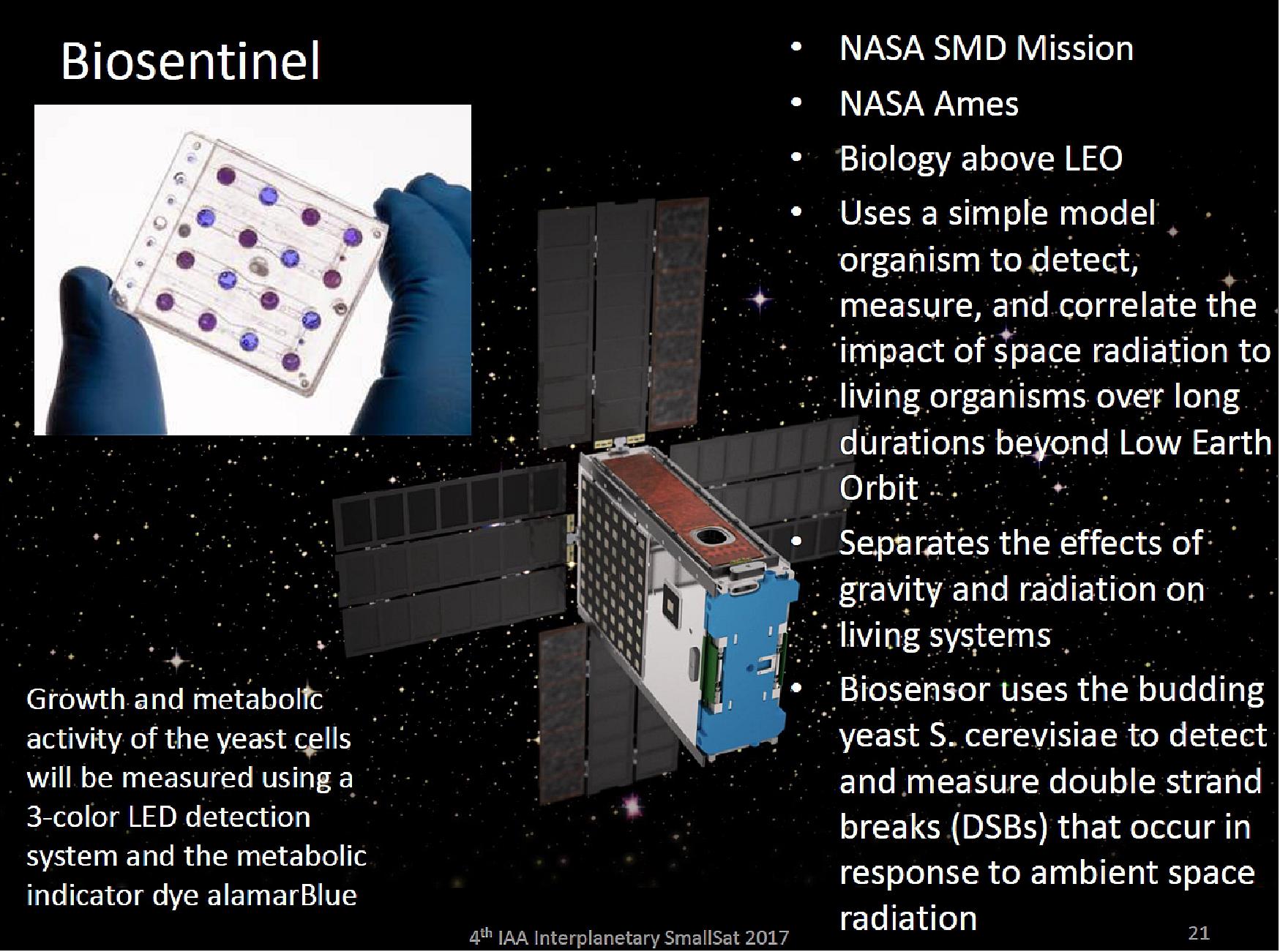
The primary objective of BioSentinel is to develop a biosensor using a simple model organism to detect, measure, and correlate the impact of space radiation on living organisms over long durations beyond LEO (Low Earth Orbit). While progress in identifying and characterizing biological radiation effects using Earth-based facilities has been significant, no terrestrial source duplicates the unique space radiation environment. 18)
The BioSentinel biosensor uses the budding yeast S. cerevisiae to detect and measure DSBs (Double Strand Breaks) that occur in response to ambient space radiation. DSBs are deleterious DNS lesions that are generated by exposure to highly energetic particles in the deep-space radiation without errors by the cell. The biosensor consists of genetically engineered yeast strains and nutrient selection strategies that ensure that only cells that have repaired DSBs will grow in specialized media. Therefore, culture growth and metabolic activity of yeast cells directly indicate a successful DSB-and-repair event.
BioSentinel Science Concept: 19)
• Quantify DNA damage from the space radiation environment
- Space environment cannot be reproduced on Earth
- Omnidirectional, continuous, low flux with varying particle types
- Health risk for humans spending long durations beyond LEO
- Radiation flux can spike 1000 x during a SPE (Solar Particle Event).
• Correlate biologic response with TID and LET data
- BioSensor payload uses engineered S. cerevisiae
- Measures rate of DSBs (Double Strand Breaks) in DNA
- LET spectrometer measures particle energy and count
- TID dosimeter measures integrated deposited energy
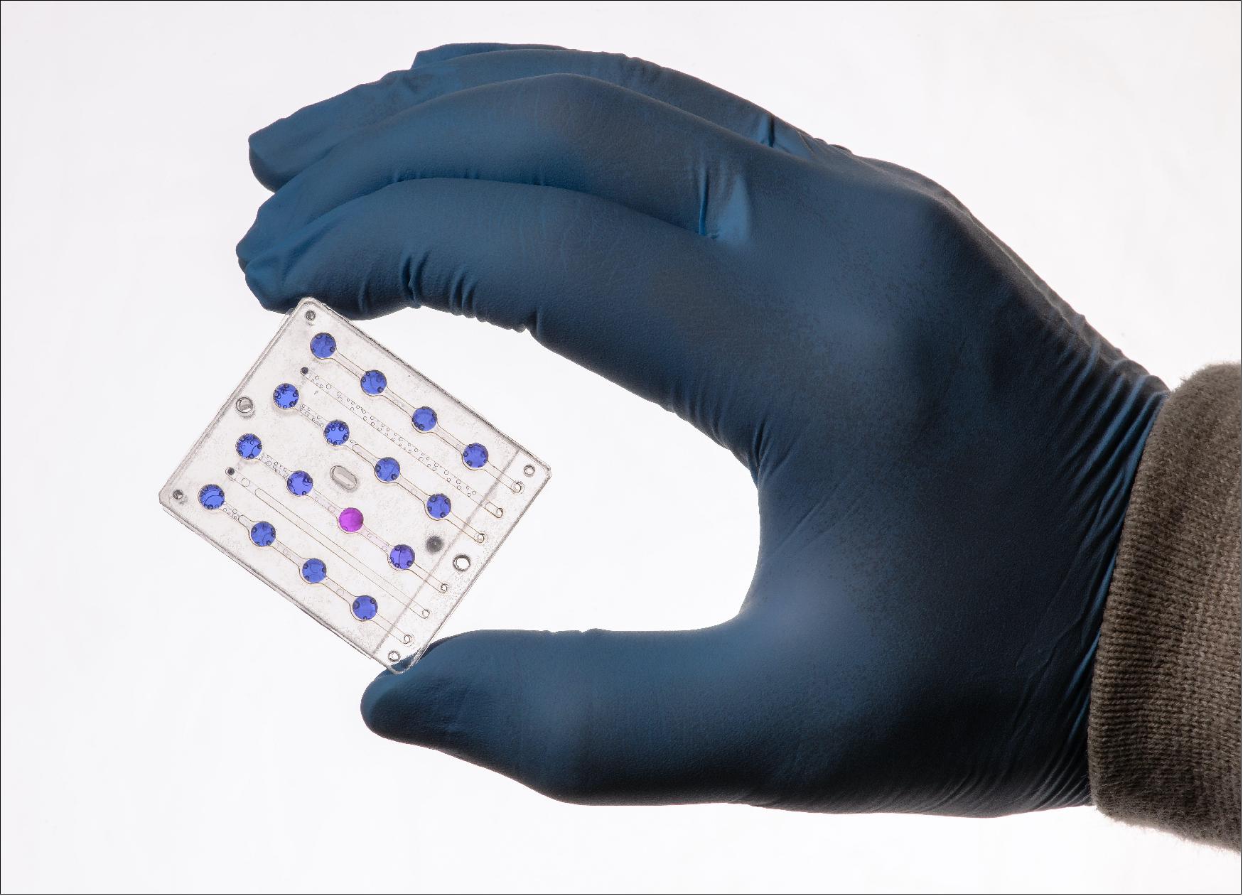
• Yeast assay uses microfluidic arrays to monitor for DSBs
- Three strains of S. cerevisiae, two controls and an engineered strain
- Wet and activate multiple sets of microwells over the mission lifetime
- DSB and associated repair enable cell growth and division of the engineered “biosentinel” strain
- Activate reserve wells in event of an SPE.
Ground Segment
RF communications
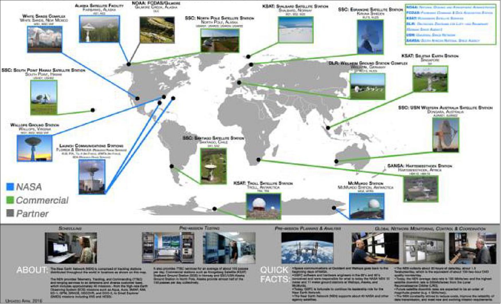
The NASA NEN (Near Earth Network) is comprised of stations distributed throughout the world in locations including Svalbard, Norway; Fairbanks, Alaska; Santiago, Chile; McMurdo, Antarctica; and Wallops Island, Virginia. Figure 1 is an overview of the NEN. The NEN supports spacecraft trajectories from near-Earth to two million kilometres (Ref. 7).
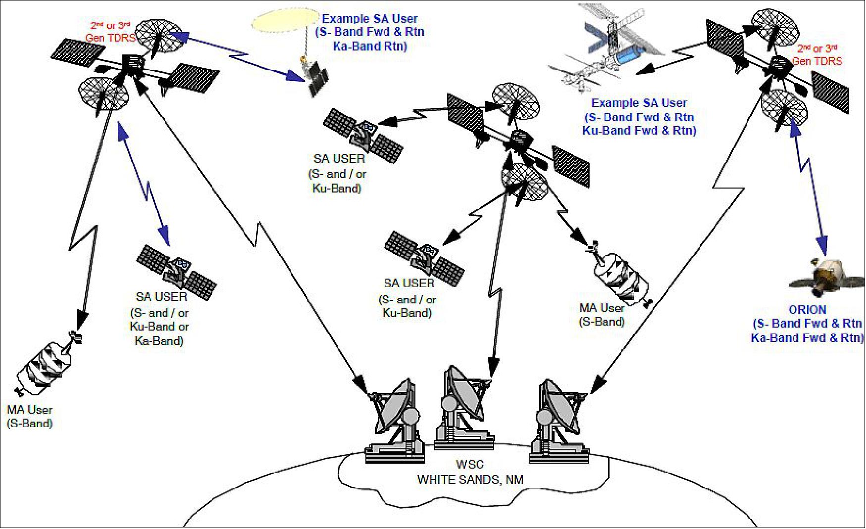
The NASA TDRS (Tracking and Data Relay Satellite) System provides continuous global communications and tracking services to low-earth orbiting satellites including the International Space Station, earth-observing satellites, aircraft, scientific balloons, expendable launch vehicles, and terrestrial systems. The global TDRS fleet currently consists of four first-generation, three second-generation and two third-generation satellites supported by three tracking stations, two at White Sands, New Mexico, and a third on the Pacific island of Guam. The third third-generation satellites will be deployed in early 2018. This combination of nine relay satellites and three ground stations comprises NASA’s Space Network (SN). Figure 15 provides a representative overview of the NASA SN.
CubeSats and SmallSats provide a cost-effective, high return on investment for conducting science missions by using miniaturized scientific instruments and bus components. Higher data rate CubeSats are transitioning away from Amateur Radio bands to S- and X-bands in the near and mid-term and Ka-band in the long term, now requiring CubeSat communication hardware standardization and compatibility with NEN and SN. Based on a high-level communication architecture for future space-to-ground CubeSat communication proposed within NASA/GSFC,
Results of the CubeSat NEN (Near Earth Network) and SN (Space Network) support analysis are provided. CubeSat constellation concept and ISL (Intersatellite Link) CDMA (Coded Division Multiple Access) signal model and trades study are discussed. A simulation model with power and bandwidth efficient signal schemes to study CubeSat maximum achievable data rate for NEN space science X-band downlink 10 MHz channel is presented and the results are discussed. Results of NEN CubeSat Ka-band end-to-end communication analysis using a portable antenna system are summarized.
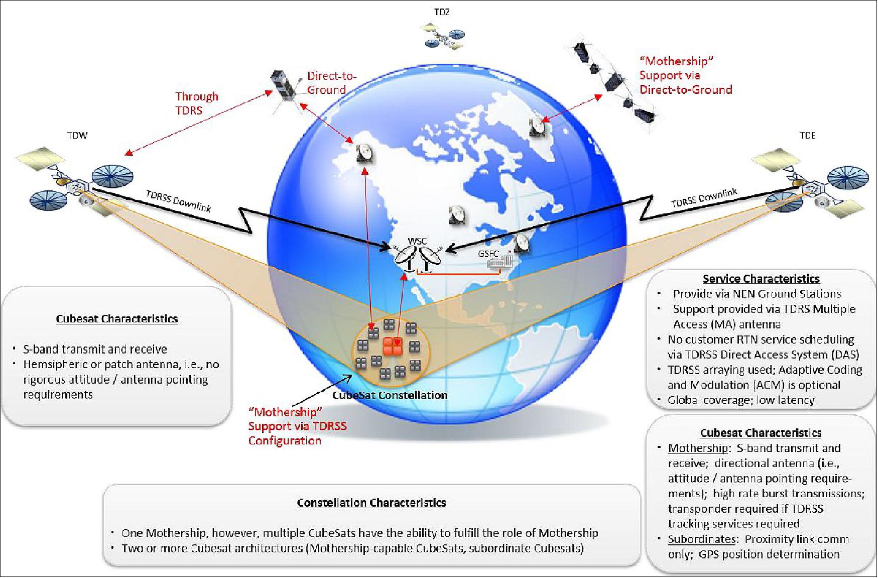
The proposed NASA future CubeSat/SmallSat communication configurations are depicted in Figure 16: CubeSat to NEN direct-to-ground communication, CubeSat to TDRSS MA array communication, CubeSat constellation with mother ship communication through NEN direct-to-ground communication, and CubeSat Constellation with mother ship communication through TDRSS MA array or KSA/SSA (K-band Single Access)/S-band Single Access).
Links | Data rate | Modulation & coding | CubeSat EIRP | Link Margin |
S-band downlink | 2 kbit/s | BPSK, ½ convolution + RS | -1 dBW | 40.1 dB |
S-band downlink | 4 kbit/s | BPSK, ½ convolution | -1 dBW | 36.5 dB |
S-band downlink | 256 kbit/s | BPSK, ½ convolution | -1 dBW | 18.45 dB |
S-band downlink | 513.7 kbit/s | BPSK, RS (Reed Solomon) | -1 dBW | 14.4 dB |
X-band downlink | 13.1 Mbit/s | QPSK, 7/8 LDPC | 5 dBW | 10.3 dB |
X-band downlink | 130 Mbit/s | QPSK, ½ convolution + RS | 5 dBW | 3.2 dB |
Legend to Table 2: 11.3 m at AS1, CubeSat PA = 1 W, 0 dBi Antenna Gain (S-band), Antenna Gain = 5 dBi (X-band). S/C at 745 km altitude.
The required Cubesat EIRP can be met with practical spacecraft (S/C) power amplifier (PA) 1 W/2 W and patch antenna zero dBi gain (S-band) Earth coverage antenna 6 dBi gain (X-band) with plenty of link margin. Table 2 is a summary of the link analysis for representative date rate, required EIRP, modulation and coding schemes, ground station parameters and link margin.
References
1) Brian Lewis, Robert Hanel, Sharmila Bhattacharya, Antonio J. Ricco, Elwood Agasid, Debra Reiss-Bubenheim, Tore Straume, Macarena Parra, Travis Boone, Sergio Santa Maria, Ming Tan, Robert Bowman, Matthew Sorgenfrei, Matthew Nehrenz, Marina Gandlin, Terry Lusby, Vanessa Kuroda, Craig Pires, Abraham Rademacher, Joshua Benton, Shang Wu, Benjamin Klamm, Charles Friedericks, Colleen Hake,”BioSentinel: Monitoring DNA Damage Repair Beyond Low Earth Orbit on a 6U Nanosatellite,” Proceedings of the AIAA/USU Conference on Small Satellites, Logan, Utah, USA, August 2-7, 2014, paper: SSC14-VII-3, URL: http://digitalcommons.usu.edu/cgi/viewcontent.cgi?article=3060&context=smallsat
2) ”NASA BioSentinel Fact Sheet,” URL: [web source no longer available]
3) Hugo Sanchez, James Chartres, Robert Hanel, Sharmila Bhattacharya, Antonio Ricco, et al., ”BioSentinel A 6U Nanosatellite for Deep Space Biological Science,” 13thAnnual Summer CubeSat Developers’ Workshop, Logan, UT, USA, August 6, 2016, URL: http://digitalcommons.usu.edu/cgi/viewcontent.cgi?article=3453&context=smallsat
4) David Korsmayer, ”CubeSats and Science Return,” The National Academies’ Meeting on Achieving Science Goals with CubeSats, 2-3 September 2-3 2015, URL: https://sites.nationalacademies.org/cs/groups/ssbsite/documents/webpage/ssb_167820.pdf
5) ”BioSentinel,” NASA, 15 April 23019, URL: https://web.archive.org/web/20230925131322/https://www.nasa.gov/centers/ames/engineering/projects/biosentinel.html
6) Stephen Battersby, ”Inner Worings: CubeSats set to tackle living systems, effects of deep space radiation,” PNAS (Proceedings of the National Academy of Sciences, USA) 10 October 2017, Vol. 114, No 41, pp: 10805–10807, URL: http://www.pnas.org/content/pnas/114/41/10805.full.pdf
7) Yen F Wong, Obadiah Kegege, Scott H Schaire, George Bussey, Serhat Altunc, ”An Optimum Space-to-Ground Communication Concept for CubeSat Platform Utilizing NASA Space Network and Near Earth Network,” Proceedings of the 30th Annual AIAA/USU SmallSat Conference, Logan UT, USA, August 6-11, 2016, paper: SSC16-IX-04, URL: http://digitalcommons.usu.edu/cgi/viewcontent.cgi?article=3367&context=smallsat
8) Terry Stevenson, Glenn Lightsey, ”Design and Characterization of a 3D-Printed Attitude Control Thruster for an Interplanetary 6U CubeSat,”Proceedings of the 30th Annual AIAA/USU SmallSat Conference, Logan UT, USA, August 6-11, 2016, paper: SSC16-V-5, URL: http://digitalcommons.usu.edu/cgi/
viewcontent.cgi?article=3373&context=smallsat
9) ”NASA's BioSentinel Smallsat Selects DDC's NAND Flash Memory for OBC Integration,” Satnews Daily, 12 September 2018, URL: http://www.satnews.com/story.php?number=2095587544
10) ”NASA’s BioSentinel Team Prepares CubeSat For Deep Space Flight,” NASA Feature, 2 April 2021, URL: https://www.nasa.gov/feature/ames/
nasa-s-biosentinel-team-prepares-cubesat-for-deep-space-flight
11) Philip Sloss, ”EM-1 Update: Making progress, but still behind schedule,” NASA Spaceflight.com, 3 April 2018, URL: https://www.nasaspaceflight.com/2018/04/em-1-update-progress-still-behind-schedule/
12) Kathryn Hambleton, Kim Newton, / Shannon Ridinger, ”NASA Space Launch System’s First Flight to Send Small Sci-Tech Satellites Into Space,” NASA Press Release 16-011, Feb. 2, 2016, URL: http://www.nasa.gov/press-release/
nasa-space-launch-system-s-first-flight-to-send-small-sci-tech-satellites-into-space
13) Christopher Moore, Jitendra Joshi, Nicole Herrmann, ”Deep-Space CubeSats on Exploration Mission-1,” Proceedings of the 68th IAC (International Astronautical Congress), Adelaide, Australia, 25-29 Sept. 2017, paper:IAC-17-B4.8
14) ”Three DIY CubeSats Score Rides on NASA’s First Flight of Orion, Space Launch System,” NASA Release 17-055, 8 June 2017, URL: https://www.nasa.gov/press-release/
three-diy-cubesats-score-rides-on-nasa-s-first-flight-of-orion-space-launch-system
15) Kathryn Hambleton, Kim Henry, Tracy McMahan, ”International Partners Provide Science Satellites for America’s Space Launch System Maiden Flight,” NASA, 26 May 2016 and update of 07 February 2018, URL: https://www.nasa.gov/exploration/systems/sls/
international-partners-provide-cubesats-for-sls-maiden-flight
16) ”Smallsats Of Scientific Persuasions To Be Supplied By International Partners To NASA For The Maiden Flight Of SLS,” Satnews Daily, May 31, 2016, URL: http://www.satnews.com/story.php?number=1735749470
17) Kimberly F. Robinson, Scott F. Spearing, David Hitt, ”NASA’s Space Launch System: Opportunities for Small Satellites to Deep Space Destinations,” Proceedings of the 32nd Annual AIAA/USU Conference on Small Satellites, Logan UT, USA, Aug. 4-9, 2018, paper: SSC18-IX-02, URL: https://digitalcommons.usu.edu/cgi/viewcontent.cgi?article=4119&context=smallsat
18) Yael Kovo, ”BioSentinel,” NASA, January 29, 2016 (updated Aug. 4, 2017), URL: https://web.archive.org/web/20230925131322/https://www.nasa.gov/centers/ames/engineering/projects/biosentinel.html
19) Brian Lewis, ”BioSentinel: Monitoring DNA Damage Beyond Low Earth Orbit on a 6U Nanosatellite,” 2017, URL: http://digitalcommons.usu.edu/cgi/viewcontent.cgi?
filename=0&article=3060&context=smallsat&type=additional
Spacecraft Launch Sensor Complement Ground Segment References Back to top