BEESAT-2 and 3 (Berlin Experimental and Educational Satellite-2 and 3)
Non-EO
Operational (extended)
Technical University of Berlin
Quick facts
Overview
| Mission type | Non-EO |
| Agency | Technical University of Berlin |
| Mission status | Operational (extended) |
| Launch date | 19 Apr 2013 |
BEESAT-2 and 3 (Berlin Experimental and Educational Satellite-2 and -3)
Spacecraft Launch Mission Status Sensor Complement References
BEESAT-2
BEESAT-2 is a follow-up mission of BEESAT-1 of TU Berlin with the objective to improve the validation of reaction wheels (RW-1) and targets 3-axis stabilization using sun sensors, magnetic field sensors, magnetic coils and reaction wheels. The reaction wheels were developed in cooperation with Astro- und Feinwerktechnik Adlershof GmbH (AstroFein). BEESAT-2 and BEESAT-3 are scheduled to be launched on the Bion M-1 satellite mission of Russia in April 2013. 1)
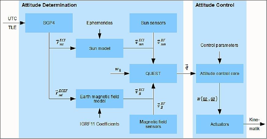
ADCS (Attitude Determination and Control Subsystem): A 3-axis stabilization is implemented on BEESAT-2.
• Attitude control rate: 2 Hz
• Sensors: Sun sensors, Earth magnetic field sensors, gyros
• Actuators: reaction wheels, magnetic coils
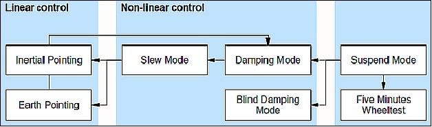
• ADCS software implemented as state machine:
- After switch-on ADCS is in suspend mode – attitude is determined, but not controlled
- With a TC a control core can be activated or a wheel test can be conducted
Angular momentum | 5.8 x 10⁻⁴ Nms at 8000 rpm |
Maximum speed | 16000 rpm |
Resolution | 0.25 rpm |
Torque | 23 x 10-6 Nm |
Mass of reaction wheels (3 wheels + electronics | 105 g |
Electrical power | ≤0.62 W (1 wheel + electronics) |
Technology | BEESAT-1 | BEESAT-2 | BEESAT-3 |
Fault-tolerant satellite design | yes | yes | - |
Multi-function component assembly | yes | yes | yes |
Reaction wheels | yes | yes | - |
Sun sensors | yes | yes | yes |
3-axis stabilization | - | yes | - |
S-band transmitter | - | - | yes |
Universal TC/TM system | - | yes | yes |
ISL (Intersatellite Link) | - | TBC | TBC |
BEESAT-3
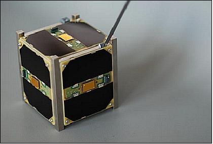
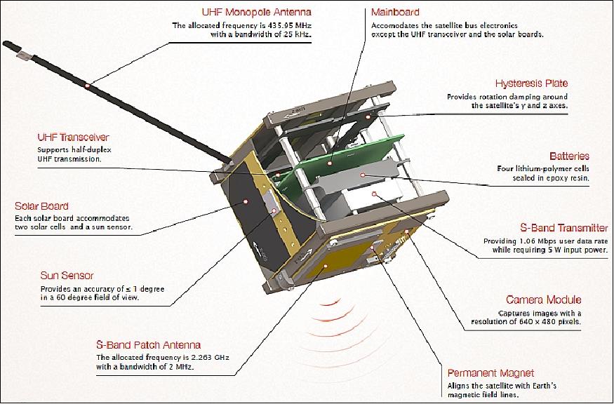
BEESAT-3, a picosatellite complying with the 1U CubeSat design specification in size and mass, is the most recent development within the BEESAT CubeSat series of the Department of Aeronautics and Astronautics at TU (Technische Universität) Berlin, Germany. The project is supported by DLR (German Aerospace Center).
The primary objective of the BEESAT-3 mission is to enrich the space engineering education at TU Berlin with hands-on spacecraft design experience. Therefore, the satellite was developed from scratch by students of TU Berlin. The secondary mission objective is the on-orbit validation of HiSPiCO (Highly Integrated S-band transmitter for Pico and Nanosatellites), which was developed in a previous research project at TU Berlin in cooperation with IQ wireless GmbH. The goal of HiSPiCO is to answer the need for high downlink data rates of CubeSat payloads. 2) 3)
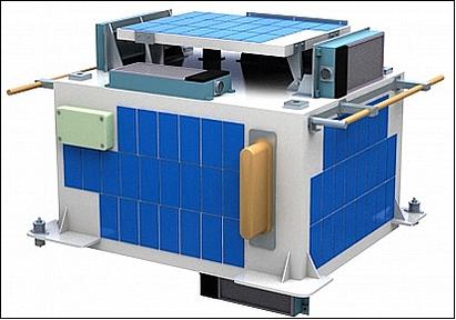
Spacecraft
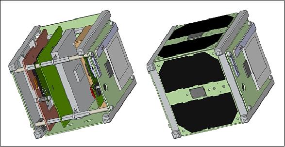
The BEESAT-3 bus structure is a custom made, three parts aluminum structure coated with an electroless nickel layer to improve its thermal properties and surface hardness. The top panel, square tube and base plate are assembled to form the satellite structure. Two rail pairs are part of the base and the top plate, which minimizes the launch stresses at the structure connection points. Inside the structure mainboard, battery and hysteresis plate are stacked on the four bolts that connect base and top plate.
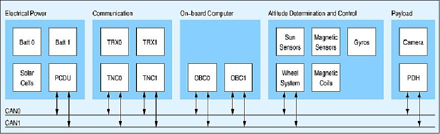
To maximize the mass and space available for the payload, all satellite bus electronics, except for the transceiver module are integrated in a single PCB (Printed Circuit Board). Figure 5shows the BEESAT-3 mainboard, which accommodates the on-board data handling, the EPS (Electrical Power Subsystem), the attitude sensors (except for the sun sensors, which are accommodated on the solar panels), the modem and the payload data handling.
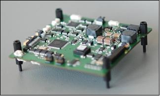
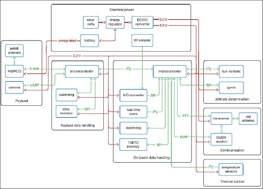
A block diagram of BEESAT-3, depicting the electronic components of each subsystem as well as the data and energy flow between these components, is shown in Figure 7. The EPS of the satellite is based on a 3.3 V and a 5 V power bus and an additional, unregulated power line is provided for the HiSPiCO transmitter. The on-board computer provides a SPI (Serial Peripheral Interface) bus and an I2C (Inter-Integrated Circuit) bus for the communication with sensors, subsystems, and payload controller.
ADCS (Attitude Determination and Control Subsystem): Although not required for the mission, the satellite is equipped with an ADCS consisting of six sun sensors and three MEMS gyros. The gained data will be used to verify the satellites attitude during S-band transmissions and to generate data for refining the BEESAT-3 attitude simulations.
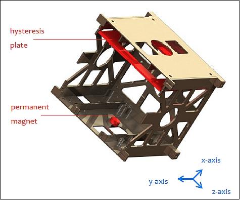
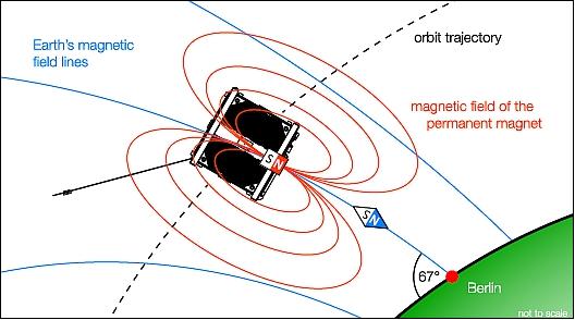
A passive attitude control system was selected for BEESAT-3, since it provides sufficient pointing accuracy for the patch antenna, without requiring energy or computing power from the satellite bus. The BEESAT-3 passive attitude control system consists of a permanent magnet that aligns the satellite to the magnetic field lines and a hysteresis plate, which damps the nutation of the satellite. The position of the permanent magnet and the hysteresis plate within the structure is shown in Figure 8.
Since only one side of the satellite is equipped with a patch antenna, the passive attitude control system needs to be designed such that a correct pointing of the patch antenna is guaranteed when the satellite passes over the ground station. Due to the IGRF (International Geomagnetic Reference Field) model, the angle between the magnetic field lines and the orbital altitude of 575 km at the ground station in Berlin (52°30'54''N, 13°19'25''E) is 67.13º. To direct the patch antenna to the ground station, the permanent magnet is aligned with the satellite's x-axis, which results in an angle of 22.83º between patch antenna and ground, when the satellite passes the ground station.
Figure 4 shows how the magnetic field of the permanent magnet aligns to Earth's magnetic field when BEESAT-3 passes the TU Berlin ground station. The hysteresis plate is aligned to the satellite's y-z plane so that rotations around the y- and z-axis are damped, whereas rotations around the satellite's x-axis remain undamped.
RF communications: The communications subsystem consists of a GMSK modem and a transceiver BK77 of the company: STE sas Elettronica Telecomunicazioni , Milan, Italy. This transceiver was already successfully used for the BEESAT-1 mission and supports half-duplex UHF communications.
Universal TC/TM system characteristics implemented:
• Event-based protocol approach
• Half-duplex communication in UHF
• Address oriented messages
• Messages are acknowledged – transmission errors result in retransmission of single data packets
• Satellites and ground station are network nodes
• A node can forward messages → swarm capable protocol
• Terminal node controller (TNC) will be open source hardware to build up a compatible ground station with listen-only mode
• TM organized similar to CCSDS
• Ground segment configurable to several missions using a database.
Frequency | 435-438 MHz (UHF) |
Modulation | GMSK (Gaussian Minimum Shift Keying) |
FEC (Forward Error Correction) | Proprietary |
Channel bandwidth | 12.5 or 25.0 kHz |
Data rate (gros) | 4.8 or 9.6 kbit/s |
User packet size | 18 Byte |
Maximum user message size | 576 Byte |
Launch
The BEESAT-2 and BEESAT-3 CubeSats were launched on April 19, 2013 as secondary payloads on the primary spacecraft Bion-M1 (with biological and medical payloads of Russia and an international community) with a Soyuz-2.1b rocket. The launch site was the Baikonur launch facility, Kazakhstan. 5) 6)
Orbit: Initial elliptical orbit with an altitude of ~300 km x 575 km, inclination = 64.9º. After separation from the launch vehicle, the Bion-M1 spacecraft circularizes its orbit to the altitude of 575 km. The secondary payloads will be deployed from Bion-M1 after the target orbit is reached (~2 days after launch).
The Bion capsule will parachute back to Earth after a one-month mission. The Bion-M1 spacecraft has a launch mass of ~6,840 kg.
Secondary Payloads
• BEESAT-2, a 1U CubeSat of TU Berlin
• BEESAT-3, a 1U CubeSat of TU Berlin
• SOMP (Students' Oxygen Measurement Project) of TU (Technische Universität) Dresden, or Dresden University of Technology, Germany.
• OSSI-1 (Open Source Satellite Initiative), an amateur radio CubeSat initiated by the Korean artist Song Hojun. The satellite will carry a 145 Mhz beacon as well as a data communications transceiver in the 435 MHz (UHF) band. It will also carry a 44 W LED (Light-Emitting Diode) array to flash Morse code messages to observers on Earth.
• Dove-2 , a nanosatellite (3U CubeSat, ~ 5.8 kg) technology demonstration mission of Cosmogia Inc. (Sunnyvale, CA, USA).
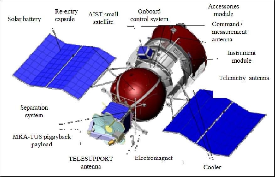
• AIST-2 is a Russian microsatellite project, a technology demonstration, developed and designed by students, postgraduates and scientists of the Samara Aerospace University in cooperation with TsSKB Progress of Samara, Russia. The microsatellite with a mass of 39 kg will perform a 3 year mission dedicated to measurements of the geomagnetic field and to test methods to compensate low-frequency microaccelerations. Also, the spacecraft will study high-speed mechanical particles of natural and artificial origin.
Mission Status
• October 2018: After successful separation on the 21st of April 2013, radio contact to the satellite could not be established with BEESAT-3. Thereupon, a comprehensive failure analysis was performed. But, although potential for improvement of the spacecraft design could be revealed, all scenarios that led to the immediate loss of the mission were classified as unlikely. In the following years sporadic attempts to receive a signal of BEESAT-3 failed. In 2017, a second evaluation of possible failure modes was conducted. After a comprehensive review of the electronics design, as well as the software of the satellite, a new scenario to explain the unresponsiveness of the spacecraft was found. Yet again, first contact attempts based on this scenario failed. 8)
- On 7 January 2018, four years, eight months and 20 days after launch, an experiment was conducted in which BEESAT-3 was commanded using the ground station in Berlin, while radio amateurs from the Netherlands listened to the satellite using the 25 m parabolic antenna of the Dwingeloo Radio Observatory. Shortly after the experiment they reported that strong signals from BEESAT-3 were received. Knowing for the first time, that the spacecraft was alive and operating, the BEESAT-3 team was able to establish contact and retrieve data from the satellite using the ground station of Technische Universität Berlin. Since then BEESAT-3 is operated regularly. This paper presents the design of the BEESAT-3 satellite and recapitulates the events that ultimately lead to establishing contact to BEESAT-3 after almost five years on orbit. Furthermore, it discusses the impact of the spacecraft's weak radio signal on mission operations and presents initial orbit data of the BEESAT-3 mission.
- While telemetry from BEESAT-2 could already be received when the satellites passed the ground station in Berlin for the first time after separation, BEESAT-3 remained silent. After several more passes in which the contact could not be established it became evident that an anomaly must have had occurred. Thereupon, the BEESAT-3 team derived several scenarios to determine factors that could prevent the reception of signals from the satellite. As a next step, procedures were developed to contact the satellite despite these assumed issues. Thus, in the following months several more contact attempts were made, which involved:
1) Sending different command sequences to the spacecraft
2) Contact attempts at various elevations and cardinal points
3) Contact BEESAT-3 via BEESAT-2 in relay mode (inter-satellite link in the UHF band)
4) Commanding the spacecraft with very high transmission power
5) Contact the spacecraft at different lightning conditions
6) Attempt to receive a signal with other ground stations.
- However, none of these contact attempts resulted in receiving any signal of the satellite at the ground. In parallel with the described efforts, a comprehensive failure analysis was performed to determine the most likely root causes for the failure. In the course of this analysis, several design weaknesses of BEESAT-3 could be determined and much potential for improvements could be identified. However, no conclusive scenario that could explain the total failure of the mission despite successfully passing qualification and acceptance testing could be determined.
- In the years following launch, sporadic attempts to contact BEESAT-3 were performed without success.
- In summer 2017 the callsign of BEESAT-3 was about to expire. This triggered another investigation of the case, including a detailed analysis of the hard- and software design of the spacecraft with special focus on their interaction in different failure cases. This yielded in new scenarios supporting the assumption, that the antenna did not unfold as scheduled.
- Researching options for increasing transmission power as well as receiving gain revealed that the 25 m parabolic dish antenna of the Dwingeloo radio observatory in the Netherlands had already successfully supported several CubeSat missions in this regard.
- On 7 January 2018, the team from Dwingeloo was at the telescope and suitable passes of BEESAT-2 and BEESAT-3 were found to begin approximately at 13:30 and 14:00 UTC, respectively. Within the BEESAT-2 pass the satellite was received at Dwingeloo as expected and to the excitement of the team, also a reception of signals from BEESAT-3 was reported. An analysis quickly revealed that the received signals indeed carried the Morse code beacon of BEESAT-3. This marked the first reception of any signal from the satellite, four years, eight months and 20 days after launch.
- Knowing for the first time that BEESAT-3 was indeed responding to telecommands from the ground, another test was conducted using the ground station in Berlin and on the next day the first telemetry frames that were decoded in realtime could be received from BEESAT-3.
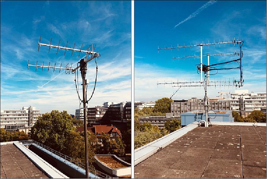
- Ground station upgrade: After BEESAT-3 was contacted regularly for several weeks in January 2018 it became obvious that the low signal strength of the spacecraft's transmitter significantly affected its operability. It was therefore decided to install a larger UHF antenna, whose additional gain was to improve the reception of the spacecraft. The antenna system that was used for operations at Technische Universität Berlin at the time consisted of two stacked X-quad antennas and offered a gain of nearly 18 dBi on paper. The new system entails four stacked cross-yagi antennas and delivers approximately 22 dBi.
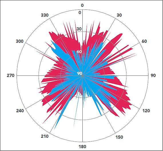
- After testing the new setup, it could be confirmed that it significantly improved the operations. Figure 15 shows a plot of the minimal elevation angles at which BEESAT-3 telemetry frames were decoded by the ground station. Here, the blue area represents the time between 7 January and 9 June 2018, in which BEESAT-3 was operated in 80 passes using the nominal antenna setup. In these passes 1,576 telemetry frames could be decoded. The red area reflects the time between 10 July and 31 August 2018 that also saw 80 operated passes, this time using the new antenna. Here, however, 6,884 frames were decoded.
- It can be clearly seen that the elevation-window in which operations can be conducted improved considerably after the new antenna was installed. Here, it needs to be noted, that the shape of the elevation window is also affected by the geometry of the spacecraft's orbit.
- Platform and payload commissioning: Soon after installing the new antenna system, commissioning of BEESAT-3 was approached. As most of the platform components were already activated upon separation, only the payload computer and the gyroscopes needed to be switched on for testing. In addition to certain hardware, some software capabilities of the platform, such as the execution of time tagged command lists or different transmission protocols, needed to be validated in orbit. All procedures required for commissioning were tested on the full-scale engineering-qualification-model of BEESAT-3 in the laboratory before being executed on orbit.
- Once the platform elements were tested comprehensively, payload commissioning was approached beginning with the S-band transmitter. Right after activating the device in a suitable pass, the receiver on the ground synchronized flawlessly and first data could be downlinked. As the passive attitude control system does not support target pointing towards the ground station, only selected passes are suitable for S-band operations. However, it could be shown that operations in passes that were identified to be well suited for S-band operations after comprehensive testing resulted in reproducible performance.
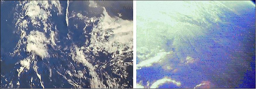
- As a next step, the camera payload was commissioned. After some adjustments of the positions in orbit at which pictures were taken, the first pictures of Earth could be downlinked to the ground via S-band. Figure 16 comprises two post-processed images of Earth that were taken at approximately 32°N 40°W on 23 August (left) and at 34°N 82°E on 5 September 2018 (right) by BEESAT-3.
- Towards nominal operations: In the two months of operations that followed the antenna upgrade it could be shown, that the satellite can be operated effectively despite its relatively weak transmission power. In order to guarantee the undisturbed execution of the payload experiments, time-tagged command lists are used even if an experiment is conducted during a ground station pass. In this manner, S-band operations are, for example, possible even before the elevation is sufficiently high for a reliable UHF link. Furthermore, using time-tagged command lists ensures, that the nominal spacecraft configuration is entered after the experiment is concluded in any case.
• BEESAT-2 and BEESAT-3 were deployed on April 21,2013 from the Bion-M1 spacecraft. A first contact was established with BEESAT-2.
Sensor / Experiment Complement (HiSPiCO, Camera)
HiSPiCO (Highly Integrated S-band transmitter for Pico and Nanosatellites)
HiSPiCO is the primary payload on BEESAT-3. The device was developed in cooperation with IQ wireless GmbH and funded by DLR.
Several verification steps have been defined for the HiSPiCO on-orbit verification process:
• Successful synchronization of the HiSPiCO transmitter with the TU Berlin ground station.
• On-board generated test data are transmitted. This data is used to assess the link quality and to calculate the bit error rate.
• Pictures taken by the camera module are downlinked to Earth in order to demonstrate the transmitter's ability to send real payload data.
• Downlinks with experimental user data rates of 0.68 Mbit/s and 1.39 Mbit/s are demonstrated and the link quality is assessed.
Table 4 shows an overview of the CubeSat missions with S-band transmission capabilities launched to date. So far only two transmitter models have been successfully demonstrated on orbit, both of them offering significantly lower data rates than HiSPiCO. Furthermore, S-Band transmission was not demonstrated with a single-unit CubeSat on orbit.
Mission/satellite | Launch | Developer | CubeSat size | S-band device | Status | Data rate (kbit/s) |
NCube-1 | 2006 | ARR/NSC | 1U | Custom design | Launch failure | - |
GeneSat-1 | 2006 | NASA/ARC | 3U | MHX-2400 | Success | 83 |
MAST | 2007 | Tethers Unlimited, Inc. | 3U | MHX-2400 | Partly successful | 83 |
CanX-2 | 2008 | University of Toronto | 3U | Custom design | Success | 256 |
PharmaSat | 2009 | NASA/ARC | 3U | MHX-2400 | Success | 83 |
O/OREOS | 2010 | NASA/ARC | 3U | MHX-2400 | Success | 83 |
RAX-1 | 2010 | University of Michigan | 3U | MHX-2400 | Success | 83 |
KySat | 2011 | Kentucky Space | 1U | MHX-2400 | launch failure | 83 |
Hermes | 2011 | University of Colorado | 1U | MHX-2400 | launch failure | 83 |
RAX-2 | 2011 | University of Michigan | 3U | MHx-2400 | Success | 83 |
Goliat | 2012 | University of Bucharest, Romania | 1U | MHX-2400 | Success | 83 |
Cinema | 2012 | UCB/SSL, NASA/ARC | 3U | Emphiser | Success | 1000 |
UKube-1 | 2013 | Clyde Space, University of Strathclyde, UK | 3U | CPUT STX | Pre-launch | 1000 |
Trio-CINEMA | 2013 | Kyung Hee University, Korea | 3U | Emphiser | Pre-launch | 1000 |
BEESAT-3 | 2013 | TU Berlin, Germany | 1U | Custom design | Pre-launch | 2000 |
Ho‘oponopono | 2013 | University of Hawaii, Mānoa | 3U | MHX2400-FT | Pre-launch | 57.6 |
Table 5 shows S-band transmitters/ transceivers suited for CubeSats that were already demonstrated on orbit or are offered for sale. It is obvious that S-band transmission data rates as high as offered by HiSPiCO have not been demonstrated from a CubeSat to date.
Manufacturer | Device | Flight heritage | Data rate (max) | Output power | Electrical power | Mass |
Microhard | MHX-2400 | 4 missions | 83 kbit/s | 30 dBm | 4.85 W | 75 g |
SFL UTIAS | CanX-2 | 1 mission | 1024 kbit/s | 27 dBm | 5 W | - |
IQ wireless | HiSPiCO | sounding rocket | 2000 kbit/s | 27 dBm | 5 W | 75 g |
ARR | Mini-Dusty trans. | sounding rocket | - | 29 dBm | - | - |
ISIS | TXS | - | 100 kbit/s | 28 dBm | 4 W | 75 g |
CPUT | STX-01 | - | 2000 kbit/s | 30 dBm | 6 W | 80 g |
Frequency | 2.2-2.3 GHz (S-band) |
RF power | 27 dBm, 500 mW |
Modulation, FEC coding | DQPSK (Differential Quadrature Phase Shift Keying), Turbo |
Channel bandwidth | 1.2 MHz |
User data rate | 1.06 Mbit/s |
Size | 95 mm x 46 mm x 15 mm |
Mass | 75 gram |
Electrical power | 5 W |
Camera
The secondary payload of BEESAT-3 is a CMOS-328 camera module that generates pictures with a resolution of 640 x 480 pixels. The camera has a focal length of 4.63 mm, f-number =2.8. The GSD (Ground Sample Distance) is 695 m from an orbital altitude of 575 km and the swath width is 445 km.
References
1) F. Baumann, S. Trowitzsch, K. Briess, C. Nitzschke, "BEESAT – A CubeSat Series Demonstrates Novel Picosatellite Technologies," 4th European CubeSat Symposium, Brussels, Belgium, Jan. 30- Feb. 1, 2012
2) Merlin F. Barschke, Frank Baumann, Klaus Briess, Christian Nitzschke, "BEESAT-3: Passive Attitude Control for Directed Radio Transmission on a Single-Unit CubeSat," Proceedings of the UN/Japan Workshop and The 4th Nanosatellite Symposium (NSS), Nagoya, Japan, Oct. 10-13, 2012, paper: NSS-04-0117
3) M. F. Barschke, F. Baumann, K. Briess, "BEESAT-3: A picosatellite developed by students," Proceedings of the 61st German Aerospace Congress (61. Deutscher Luft- und Raumfahrtkongress 2012), Berlin, Germany, Sept. 10-12, 2012
4) M. F. Barschke, F. Baumann, K. Briess, C. Nitzschke, "BEESAT-3: Passive Attitude Control for Directed Radio Transmission on a Single-Unit CubeSat," Proceedings of the UN/Japan Workshop and The 4th Nanosatellite Symposium (NSS), Nagoya, Japan, Oct. 10-13, 2012, Poster
5) Patrick Blau, "Soyuz Launch Success - Bion-M1 & various Passengers safely in Orbit," Spaceflight 101, April 19, 2013, URL: http://www.spaceflight101.com/bion-m1-mission-updates.html
6) "Five Spacecraft Launched By Two Launch Vehicles From Two Continents," Space Daily, April 23, 2013, URL: http://www.spacedaily.com/reports/Five_Spacecraft_
Launched_By_Two_Launch_Vehicles_From_Two_Continents_999.html
7) A. N. Kirilin, R.N. Akhmetov, S. I. Tkachenko, "SRP SC "TsSKB-Progress": Trends and Future Prospects," 2011, URL: http://tinyurl.com/puz437a
8) Merlin F. Barschke, Philipp Werner, Sascha Kapitola, "BEESAT-3 commissioning – better late than never," Proceedings of the 69th IAC (International Astronautical Congress) Bremen, Germany, 1-5 October 2018, paper: IAC-18.B4.3.1, URL: https://iafastro.directory/iac/proceedings/IAC-18/
IAC-18/B4/3/manuscripts/IAC-18,B4,3,1,x43324.pdf
The information compiled and edited in this article was provided by Herbert J. Kramer from his documentation of: "Observation of the Earth and Its Environment: Survey of Missions and Sensors" (Springer Verlag) as well as many other sources after the publication of the 4th edition in 2002. - Comments and corrections to this article are always welcome for further updates (eoportal@symbios.space).
Spacecraft Launch Mission Status Sensor Complement References Back to top