CUBIT (CubeSat Identification Tag)
Tools and Platforms
CUBIT (CubeSat Identification Tag)
SRI International (SRI) of Menlo Park, CA, developed the CUBIT ( CubeSat Identification Tag) radio frequency (RF) transponder to demonstrate, a low-SWaP (Size, Weight, and Power) CubeSat RF-based identification system. CUBIT addresses the growing need to identify CubeSats post deployment as mass launches become more commonplace. Such launches make it difficult to assess which radar return belongs to which CubeSat, especially with the high mortality rates seen within the CubeSat community. Conversations with developers highlighted the need for better satellite identification for improved troubleshooting. Even for functioning CubeSats, the lack of accurate two-line elements (TLEs) increased the likelihood that ground assets were improperly aimed at the correct satellite. CUBIT seeks to address this need through a low-cost RF transponder. 1)
SRI successfully demonstrated the CUBIT system during two On-Orbit operations. SRI teamed with NASA Ames for CUBIT’s first demonstration using a collocated beacon and time domain signal analysis to confirm operation. In the second demonstration, CUBIT identified a passive CubeSat during a clustered launch and confirmed its deployment when other means provided ambiguous results.
The SRI-developed CUBIT (CUBIT Identification Tag) addresses what we perceive to be a growing need for identifying CubeSats after deployment independent of main SmallSat operation. This solution can also be used to identify other space objects, acting as a buoy of sorts, to help identify and track objects in space.
A Pressing Need: Two primary developments within the space community, primarily associated with CubeSats, have prompted the need for CUBIT:
1) CubeSat proliferation: CubeSats and small satellites are growing in satellite market share due to lower launch costs (hundreds of thousands instead of tens of millions of dollars) coupled with increased launch availability (new launch vehicles focusing on small satellites supplement existing rideshare opportunities). In addition, new space architectures based on CubeSat constellations are in development.
2) CubeSat reliability: CubeSat developments typically have smaller budgets and more compressed timelines. This is coupled with increased use of COTS (Commercial off-the-Shelf) components, decreased testing, and increased risk tolerance, resulting in a dead-on-arrival (DOA) rate exceeding 18%, with fewer than 60% still operating after 2 years. 2)
In general, CubeSats are deployed in large clusters from either dedicated or rideshare opportunities. Initial identification of individual satellites is difficult, and satellite name attribution must wait until distinct radar returns are correlated with other means of identification, usually a beacon of some sort. Issues arise when beacons fail, preventing unique identification, and when passive CubeSats are present. Misidentification or lack of identification prevents ground stations from tracking the appropriate satellite and impedes communication.
System design & architecture
Design Drivers: Based on conversations with CubeSat developers, SRI developed a list of design drivers to inform the design.
Low on-orbit SWAP: Most CubeSats are volume constrained, with minimal space for additional systems. As such, CUBIT will need to be quite small to easily integrate within the main satellite structure and reduce system impact. If CUBIT requires ¼ of a U, then we believe the system would not be attractive to CubeSat developers and would be seldom used. Systems such as camera, radiators, and antennas compete for external surface area. As such, CUBIT’s external-facing segment will need to be minimized. Additional hardware may be internalized within the CubeSat and connected to the external unit via a cable. On-Orbit SWaP minimization will affect ground station design. In general, a weaker On-Orbit component will require a larger, more powerful ground component.
Minimal Integration With Host: Dependence on a relatively unreliable host CubeSat for essential systems such as power and communications reduces the utility of CUBIT and greatly increases the risk of a completely dead CubeSat with no identification methodology available. Additionally, CUBIT will need to be designed to accept different bus voltages (in the case of integrating with host power) or communication protocols (in the case of integration with host communications systems). This would greatly increase development costs. Therefore, we sought to limit integration to a physical-only interface.
Low Cost: CubeSats needing an independent identification method such as CUBIT will be the most cash-strapped projects, unable to allot additional resources for performance and verification testing. Additionally, the desire to promote wide-scale adoption prompted SRI to develop a solution consisting mostly of low-cost COTS components. This decision also enables ITAR (International Traffic in Arms Regulations) compliance and promotes the export of the technology to other nations with space launch capabilities.
Due to SRI’s extensive background in RF systems for space applications and ground stations located throughout the world, a radio-based method is proposed.
Key Design Attributes
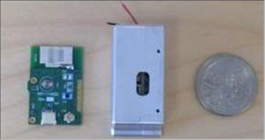
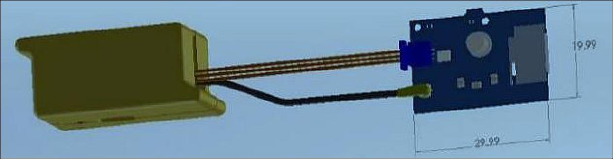
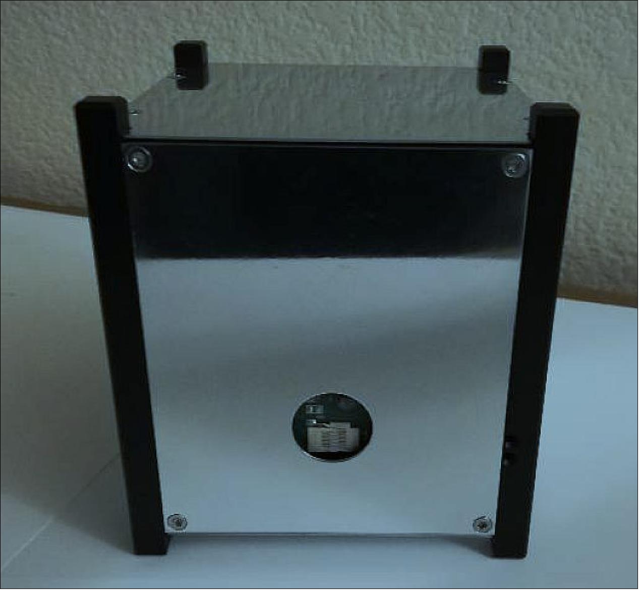
With these drivers in mind, SRI set about designing the CUBIT system. Key design attributes are presented in Table 1. The two-part system (Figure 2) consists of an internally mounted Electronics Unit (EU) and an externally mounted Antenna Unit (AU).
Feature | Value |
Electronics Unit (EU) size (mounted internally) | ~41 mm x 20 mm x 18 mm |
Antenna Unit (AU) size (mounted externally) | ~ 20 mm x 30 mm |
Mass | 21 gram |
Mounting | Two #0-80 screws, EU orientation unrestricted |
Operational frequency | 915 MHz |
Transmit power | ~0.01W, for 20 ms per each interrogation received |
Transmissions per orbit | 25/orbit. Tag will only transmit when interrogated by ground station, for total of 500 ms. |
Battery characteristics | 110 mAh @ 3.7 V |
RF inhibits | Timer: 45 min delay of tag function after launch |
Deployment power inhibits | Photocell inhibits between Power Supply and EU |
The EU consists of (1) an aluminum enclosure that houses the main battery, capable of supplying CUBIT with 30 days of power and sufficient to provide identification data during the critical mass CubeSat deployment phase, and (2) the electronics board. While the standard implementation of the CUBIT is with a standalone power supply, the system may be used with internal satellite power for prolonged operations. The EU is designed to fit in a small volume within the CubeSat structure. The microprocessor is housed on the electronics board, chosen for its low power consumption and proven performance in extreme environments.
The AU, connected to the EU by a hardline, is externally attached to the CubeSat and consists of a photo cell and antenna. The ISM ( Industrial, Scientific and Medical) 900 MHz helical-style antenna is used for receiving the interrogation signal and broadcasting the tag’s response.
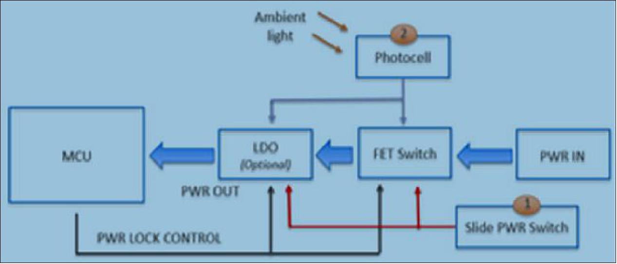
Inhibit Design
Launch requirements typically specify inactivation of secondary payloads to prevent interference with the launch vehicle. CUBIT employs multiple RF and deployment power inhibits to accomplish this. The photocell works with integrated inhibits to prevent operation prior to CubeSat deployment (a typical PEAPOD launch envelope holds the CubeSat in complete darkness until deployment). CUBIT relies on this method to prevent accidental operation prior to achieving orbit, as shown in Figure 3, a deployment switch block diagram for the CUBIT tag. The slide power switch provides the first inhibit. When switched to the “OFF” position, the power is prevented from flowing to the FET (Field Effect Transistor) switch and LDO (Low Drop Out) regulator. The photocell provides the second inhibit. Ambient light enables power to flow to the MCU (MicroController Unit) and locks the electrical pathway close, enabling operation in both day and night after initial light exposure.
Ground Segment
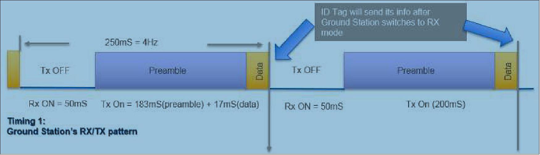
The on-orbit system is complemented by the CUBIT ground station hardware. Its current instantiation uses the same chipset to send an interrogation signal through a 10 W amplifier and SRI’s 150 ft dish. The interrogation signal can command a response from all tags, all tags except one specified, or a single specific tag. Figure 4 shows the Ground Station timing.
CONOPS (Concept of Operations) Example
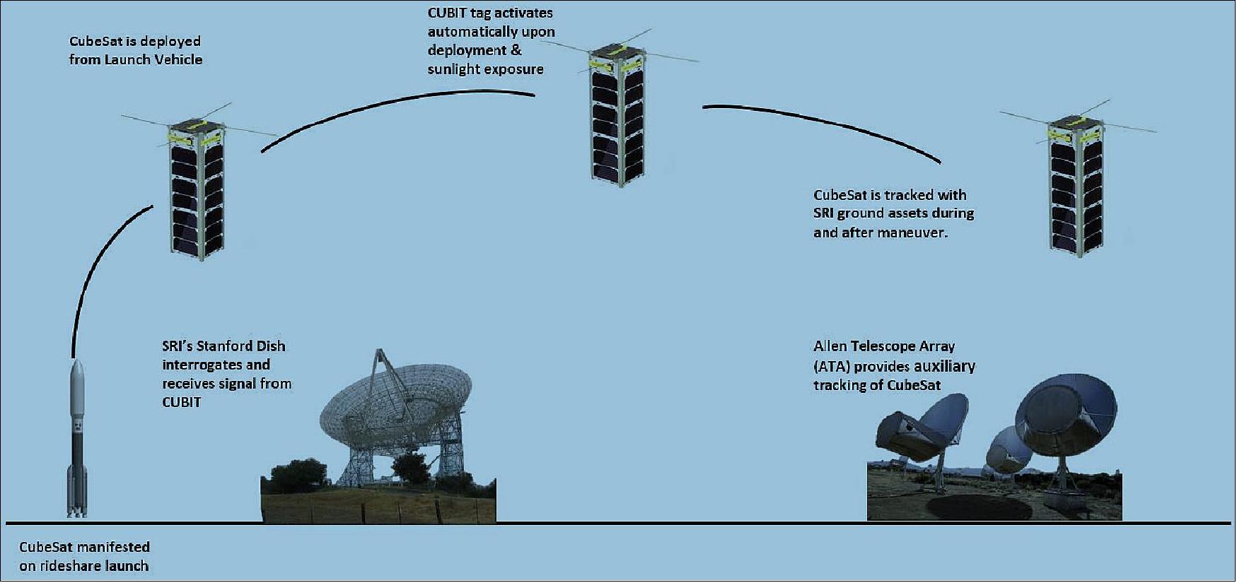
CUBIT is armed prior to deployment by flipping a physical switch while the antenna board’s photocell is in darkness, as is typical for a CubeSat within a PEAPOD. After CubeSat deployment, the photocell disengages the power inhibit and initiates a 45-minute time delay, after which the tag is ready to begin receiving interrogation. The interrogation signal is transmitted from SRI’s 150 ft dish at 915 MHz. For a space object with known orbital parameters, the satellite dish can track the assumed location while it is in view, sending interrogation signals for the duration pass within view The received coded command prompts a response by CUBIT and provides, among other things, confirmation of the commanded signal type and the tag’s device number. A CUBIT tag response can be received by the interrogation ground station or by other locations, such as the Allen Telescope Array (ATA) located in Hat Creek, CA. Ground station segments can also be set up to enable “fly through” of CubeSats for Space-Fence-like detection and identification. Figure 5 shows a CONOPS example.
On-Orbit Missions
On-Orbit Mission 1: TechEdSat 6 (TES 6)
TechEdSat 6 is a NASA-sponsored 3U CubeSat designed to demonstrate a small satellite deorbiting system. NASA Ames graciously hosted the CUBIT tag onboard, enabling SRI to successfully achieve its first On-Orbit demonstration of the technology. One modification from standard CONOPS was that CUBIT was powered by the main satellite power instead of a battery. SRI made this decision because it had high confidence that the main satellite would function and be able to provide power. The removal of the battery also reduced regulatory issues and enabled testing over an extended timeframe greater than what could be provided by the battery.
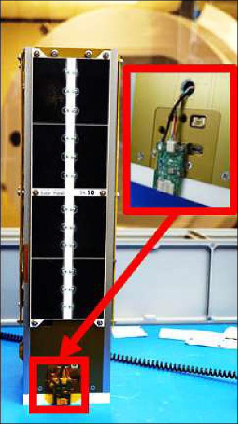
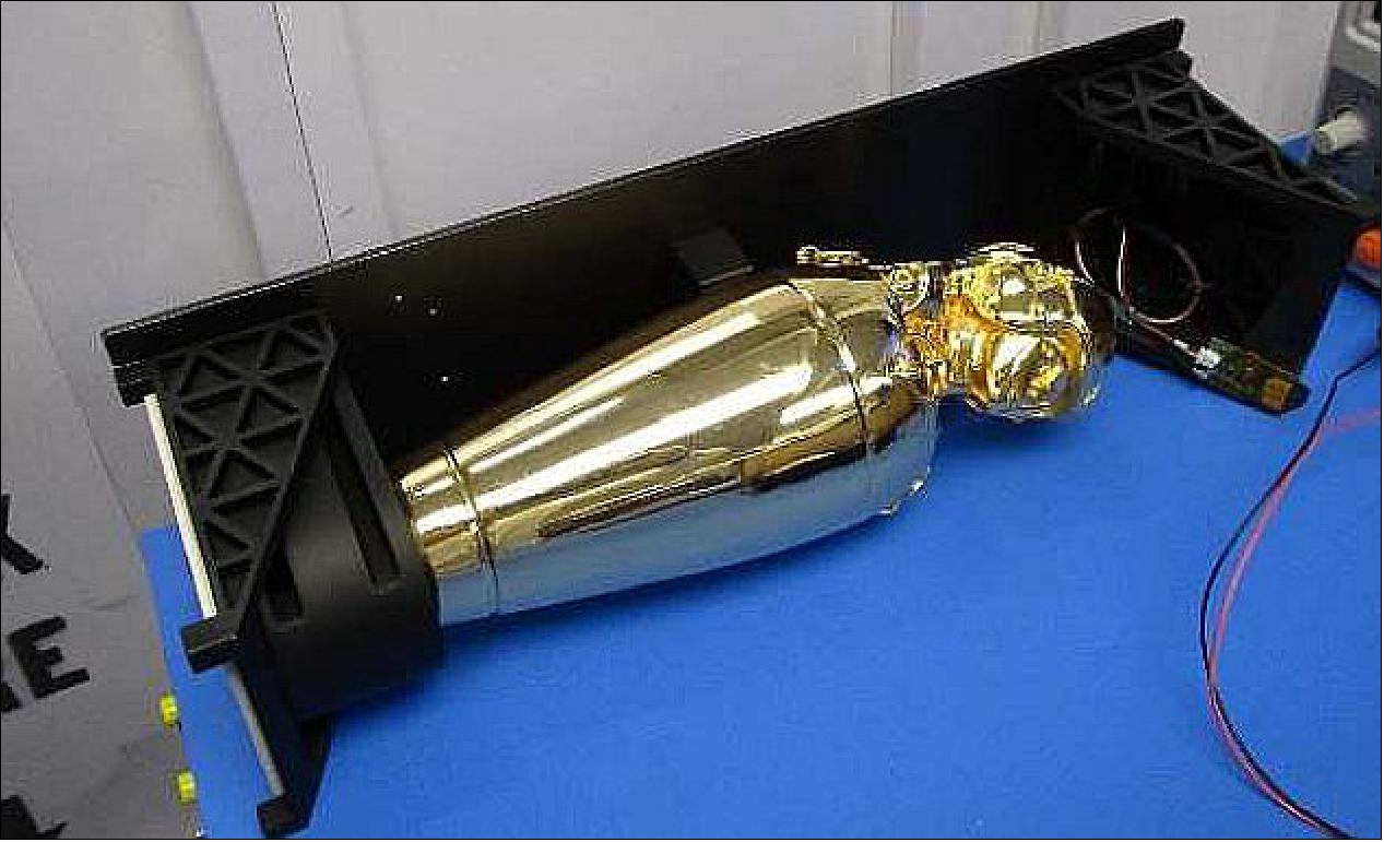
SRI’s CUBIT tag was integrated into the 3U at the base of the satellite. The AU was positioned to reduce the antenna blockage as much as possible. A power and data cable connected the two components, as shown in Figure 6. Configuration was determined through extensive meetings with the primary host.
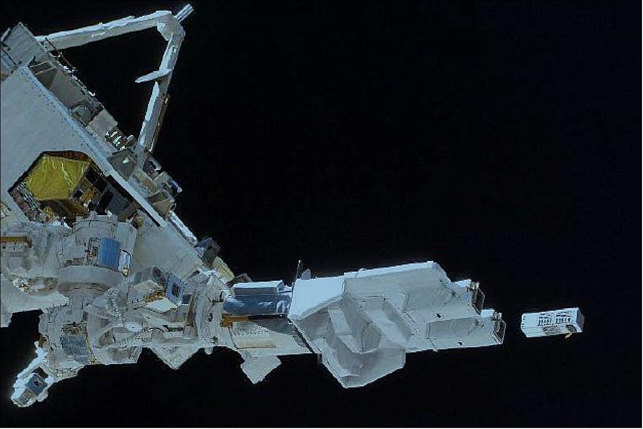
TechEdSat 6 was launched aboard a Cygnus resupply ship on 12 November 2017 and deployed from the ISS on 20 November 2017 (Figure 7). SRI’s 150-ft Dish was used as both transmitter and receiver, and the ATA was used as a receiving ground station (ATA setup is listed in Table 2) to collect at both the CUBIT tag and TES 6 frequency.
Feature | Value |
Integration size | 1 second |
Antenna array | 10 dishes |
Frequency collection center frequency | 915 MHz |
Bandwidth | 3 MHz |
Frequency bin | 1024 MHz |
Frequency collection center frequency | 2450 MHz |
Bandwidth | 100 MHz |
TLE (Two Line Element) | 43026U 98067NK 18005.16510731 .00047214 00000-0 57536-3 0 9990 |
Pass #1 | Rises: > 16.5 deg: Fri Jan 05 02:18:10 PST 2018 |
Pass #2 | Rises: > 16.5 deg: Fri Jan 05 03:53:41 PST 2018 |
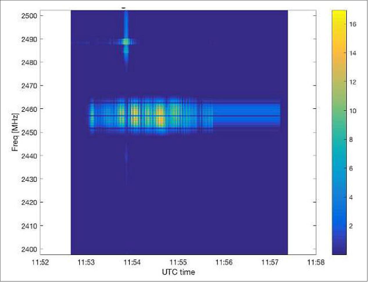
Flight Demonstration Results. Throughout the demonstration, the 150-ft Dish was not able to receive the CUBIT return signal from the on-orbit tag. Figure 8 shows the spectrogram results from the ATA, demonstrating successful tracking and acquisition of the TES6 and its 2.4 GHz beacon. Figure 9 shows a spectrogram emanating from the same location in space a signal at 915 MHz, the frequency of the CUBIT tag. As further evidence, the ATA was set up to acquire time domain data (Direct to Disk Mode). The FSK (Frequency Shift Keying) signal was an exact match of what was expected from an On-Orbit signal from a CUBIT tag (Figure 10).
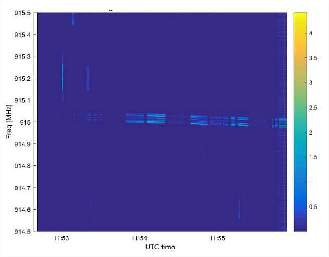
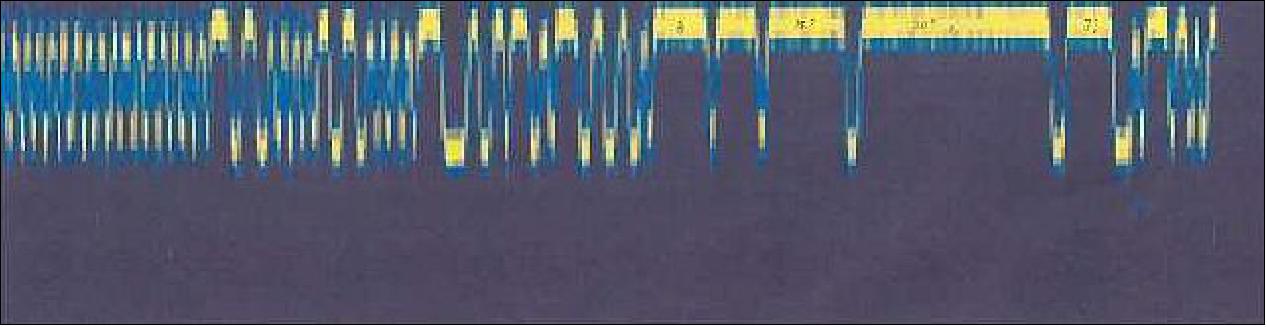
The TES 6 (TechEdSat 6) flight campaign demonstrated the hardware and proof of concept of the CUBIT tag. The CUBIT hardware was able to receive a signal from the ground segment and transmit while On-Orbit the appropriate response.
On-Orbit Mission 2: SSO-A Flight
SRI International was approached by a US Government official to assist in providing tracking and identification information for passive CubeSats to be launched onboard Spaceflight’s SSO-A (Sun Synchronous Orbit rideshare flight-A). This was to be the largest single rideshare mission from a U.S.-based launch vehicle. The presence of more than one passive CubeSat, with no identification features, as well as the possibility of several DOA satellites during the launch of 64 CubeSats, was the use case for which CUBIT was designed.
In partnership with Elysium Space, Inc. and Southern Star Group, LLC, SRI’s CUBIT tags were hosted onboard their passive CubeSats, Elysium Star 2 and Enoch, respectively (Figure 11 and Figure 12). The deployment of two CUBITs simultaneously would demonstrate the CONOPS developed by SRI on CUBIT’s operation.
The CUBITs for this flight would be battery powered and in their final configuration. SRI provided general guidance on antenna placement and overall configuration, but final placement was at the sole discretion of the CubeSat developers. This level of guidance would more closely mimic future interactions should CUBIT be used widely, and would result in a range of antenna placements that would impact identification performance. Figure 11 and Figure 12 show CubeSat and antenna placement.
Regulatory confusion on radio licensing for the Government-sponsored CUBIT prevented Elysium Star 2 from receiving deployment authority, and only Enoch was allowed to deploy. Although simultaneous deployment and discrimination were not demonstrated, value was still gained because the CUBIT power system, the only main On-Orbit hardware yet proven in space, was validated.
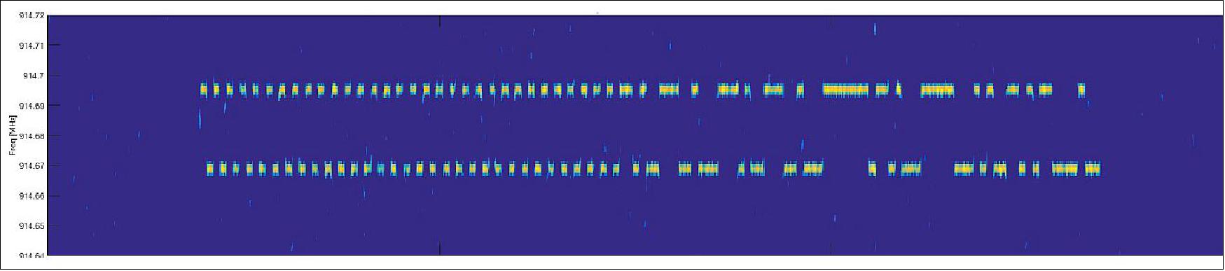
Flight Demonstration Results: SSO-A was launched from Vandenberg Air Force Base on 3 December 2018. Telemetry from the deployer provided doubt on whether Enoch was successfully deployed from the launcher. Launcher telemetry indicated the POD door containing the Enoch satellite opened, but the signal indicating full extension of the deployment spring was not received. Furthermore, the radar count for number of objects was initially one fewer than expected. A CUBIT collection event on 4 December 2018 was positive, suggesting that the CubeSat at least partially deployed, exposing the CUBIT tag to enable sufficient sunlight for activation. At that point, the deployed satellites were not sufficiently separated to attribute which radar object was Enoch.
Figure 13 shows the data collected from the ATA while it was tracking object 43777 on 4 January 2019. This, along with object count number equaling the number of expected objects, provided proof that Enoch had deployed correctly and was object 43777. This flight demonstration proved CUBIT could operate as intended: as a completely separate beacon that can aid in satellite identification. As of this writing (2 May 2019), 19 of the 65 objects associated with SSO-A have still not been identified.
In summary, CubeSat identification is a crucial matter for the community, especially as CubeSats increase in number and clustered deployments become more commonplace. While improving, the risk posture and reliability of CubeSats call for an independent method to identify CubeSats after launch.
The CUBIT system has been demonstrated in space and is proven to help identify CubeSats after launch. CUBIT tags have been integrated into a variety of satellites and other space-destined objects, demonstrating its ability to be easily added to existing systems with minimal modifications to the host (Table 3).
Host payload | Host Type | Date of Effort | Status |
TES 6 ( TechEdSat 6) | 3U CubeSat | 2016- 2017 | Launched to LEO Nov 2017. Successful acquisition |
ORS-6 (Operationally Responsive Space-6) | Minisatellite (300 kg) | 2016-2017 | De-integrated following primary payload delay |
Rocket Lab | Rocket body | 2016-2017 | De-integrated following White House Office of Science |
NASA FOP | Balloon | 2017 | De-integrated following flight delays |
Elysium Star | 1U CubeSat | 2018 | Launched Dec 2018, not deployed |
Enoch | 1U CubeSat | 2018 | Launched Dec 2018, successful acquisition |
TES-7 (TechEdSat-7) | 2U CubeSat | 2018-2020 | Pending launch in 2020 |
References
1) Samson Phan, ”SRI International’s CubeSat Identification Tag (CUBIT): System Architecture and Test Results from Two On-Orbit Demonstrations,” Proceedings of the 33rd Annual AIAA/USU Conference on Small Satellites, August 3-8, 2019, Logan, UT, USA, paper: SSC19-XI-05, URL: https://digitalcommons.usu.edu/cgi
/viewcontent.cgi?article=4451&context=smallsat
2) Martin Langer, Jasper Bouwmeester, ”Reliability of CubeSats – Statistical Data, Developers’ Beliefs and the Way Forward,” Proceedings of the 30th Annual AIAA/USU SmallSat Conference, Logan UT, USA, August 6-11, 2016, paper: SSC16-X-2, URL: https://digitalcommons.usu.edu/cgi
/viewcontent.cgi?article=3397&context=smallsat
The information compiled and edited in this article was provided by Herbert J. Kramer from his documentation of: ”Observation of the Earth and Its Environment: Survey of Missions and Sensors” (Springer Verlag) as well as many other sources after the publication of the 4th edition in 2002. - Comments and corrections to this article are always welcome for further updates (eoportal@symbios.space).